1
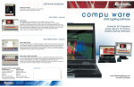
Elation Professional ART 1024 Software Guide For any questions not answered in this document or for general tech support please call 1-(323) 213-4590 between 9am-5pm Pacific Time Mon-Fri, or email [email protected] Thank you for your purchase. Page 1 of 51 This guide will cover: How to download and install the software. (32/64 Bit Operating Systems) ………Page 3. How to set up and address your fixtures. …………………………………………………………Page 7. How to edit fixtures in the 3D viewer. …………………………………………………………..Page 11. How to patch areas. ……………………………………………………………………………………..Page 18. How to create groups. …………………………………………………………………………….....…Page21. How to start programming your fixtures. ……………………………………………………..Page 23. How to use effects. ………………………………………………………………………………………Page 25. How to playback your shows. ……………………………………………………………………..Page 40. How to edit your shows. ……………………………………………………………………………….Page 42. How to transfer scenes from the software to the interface. ………………………… Page 45. How to playback your scenes on the interface. …………………………………………….Page 49. How to use interface controls to customize live playing back scenes. ……….....Page 50. NOTICE TO ALL USERS: The functionality and settings of this software are subject to change at any time without prior notification by Elation Professional via software update. The end user is encouraged to periodically check for software and library updates from the Elation Product page linked below. Likewise Elation Professional is not responsible for loss of data or corruption while updating the software or firmware of this interface and software. Always backup your important data. Page 2 of 51 Installing ART 1024 Software for Windows 32 Bit or 64 Bit Operating systems. To install the ART 1024 Software from our website go to the ART 1024 Product page found here: http://www.elationlighting.com/ProductDetails.aspx?ItemNumber=1623&MainId=1&Category =28 Or use the disc that came with your software package when you purchased it and follow the onscreen instructions. To install from our website follow the link posted above. And click on the bottom link labeled “ART 1024 SOFTWARE (exe)” If your browser prompts you to save or run select save and select the file save destination. Once done downloading click on the “art1024” icon in your saved destination. (Shown in the picture below the saved destination was desktop) Page 3 of 51 Double click the icon. Once you see the window as shown in the picture above. Select Run. Select your language then select next. Now accept our licensing agreement then select next. Now for Windows 32 bit users install the software to your C: Drive. Then select next. For Windows 64 bit users you MUST install the software to a different directory called “Program files (X86)” as shown here. Program files (X86) can be found under Program files. (NOTE: The Art 1024 folder will not be there if it is your first time installing the software.) Page 4 of 51 Selecting components: For Windows 32 and 64 Bit users. You will want to make sure the USB drivers is checked to install the proper drivers on your computer to ensure the panel interface communicates properly with the software. It is entirely the user’s discretion to install the HTML user manual files. In this example they were not installed. Once you have selected your components to install click next. Now confirm your start menu folder and select next. (Continued on next page) Page 5 of 51 Now the USB drivers will install. The picture shown above is what will appear on your screen. Click next once it appears. When it is done it will look like this. Click finish and the rest of the software will begin to install to your computer. Page 6 of 51 Once all files have been installed the window will look like the picture below. Click finish to launch the ART 1024 Software. Getting started on Art 1024 Software. Now that the ART 1024 software is installed on your computer. Double click the icon on your desktop. Now the software will load and your page should look like this: (Continued on next page) Page 7 of 51 To begin using the software you must first patch your fixtures. In the upper left hand corner of the page you will see an “Add Fixtures” icon. Click the icon and your screen should look like the above picture. In the lower large red circle you will see your Scan Library. This library contains all the folders to all the lighting manufactures that we currently have profiles for. Browse this menu to find the company of the fixtures you are using. For this example we will use some generic RGB LED panels (found in the generic folder) and some Elation fixtures. Page 8 of 51 As shown in the picture above. You can expand company folders and product series folders to find the exact profile you are looking for. In the picture, we have already patched our RGB LED panels from the generic folder as shown in the channel grid. Now we want to patch our Design Spot 250’s. You can see the software will straight patch fixtures, picking up where the last channel of the last fixture left off. We have selected the Design Spot’s to start at channel 37 and we have selected two fixtures. Now we hit the patch button and the DMX channel Grid will patch those fixtures for us. In this next picture as shown above. We are selecting DLED 36 in 6 channel mode. And we have selected six of them. Click on the patch button and the final DMX channel grid should look like this with the fixtures we have selected. (Shown in picture below) Page 9 of 51 Now hit ok. And the fixtures will be patched to the software allowing you to control them. Please double check all DMX addresses and DMX modes on the actual fixtures before you begin to program. Your page will look like this. (Picture below) Page 10 of 51 Setting up your fixtures in the 3D viewer. (Setting up the 3D viewer is not a requirement. If you wish to skip this step please move down to page 18.) Now that we have our fixtures patched we will want to set them up in the 3D viewer. Click on the Easy view (3D) icon as shown in the picture below. Now your 3D window will load and it will look like the picture below. You will notice all your fixtures are in a line. To change this and set the positions you will need to enter construction mode and then click on the fixtures tab to see all your fixtures. Page 11 of 51 To move your fixtures around the 3D space, you can click on the fixtures folder to select all of the fixtures at once. In the picture below you will see that all of the RGB LED panels are selected and you are able to move them all using the X Y Z positions table by clicking on the up or down arrows. The X Y Z functions are explained in the picture. X moves the selected fixtures left to right. Y moves the selected fixtures up or down. And Z moves the selected fixtures front to back of the 3D space. In this next example we are going to matrix the positions of our RGB LED panels. You can do this by going to the positions wizard. You will first need to select matrix on the bottom of the options for the positions matrix. Once you click on the dot for positions matrix you will get a window to appear with some options. Page 12 of 51 In the picture above I have selected matrix and the small window is asking me how I want the positions grouped. You can select different grouping options by clicking on the arrow to drop down a menu of numbers. For this example I have chosen a 2X6 grid. (Not pictured) The next step once you have selected your grid positions, to hit OK and the next following window will appear. What this window is telling you is how the addresses of the fixtures will be positioned. In the picture you will see I have two lines of 6 fixtures. You can adjust how this is read by clicking on the “Advanced positioning” text. But we will not do that as this is the positioning we want. Now once you hit ok on the matrix patch window the window will disappear thus selecting your settings into the positions wizard. You can now adjust the matrix you have selected as shown in the picture below by adjust the two faders that will appear in the positions wizard tab. Each fader will adjust all the fixtures evenly away or together on a X and Z axis. Page 13 of 51 Now once you have got your matrix of positions done you can then move them all as one object Left to right back to front and up and down by selecting the Fixture folder and clicking on the arrows of X Y Z. Now there is also the option to rotate individual fixtures. For example to hang lights upside down or sideways on the truss or even floor mount them. You can do this by selecting your fixture(s) and adjust the dX dY dZ values to the right of the X Y Z positions. It is best to play around with all these functions so that you may get a better understanding of their functions. Page 14 of 51 To individually select one fixture simply expand the fixture folder and left click then right click on one fixture. You may also repeat those steps to group fixtures together. For example I have 6 DLED 36 and I want to move them in 2 groups of three. I would have to expand the DLED 36 fixture folder. Then Left click on the first fixture then right click to select it then repeat those last two steps for the next two fixtures. In the picture below you will see three of the 6 DLED 36’s selected. And the DLED 36’s final positions are 3 on the left side and three on the right side angled to shoot on the ceiling. Page 15 of 51 You will also notice at the top of the window the rendering tab is selected. In this tab you can select how bright your ambient light is and how strong your light beams are (atmospheric effects like fog or haze) also while the 3D window is in the foreground of windows you can hit your left and right arrow keys on your keyboard to adjust the light beams and the up and down arrow keys to adjust the ambient light. In the picture above you will see under the standard toolbar tab that I have selected stage settings. Stage settings allow you to adjust the height, length, and width of the stage you are building in either meters or feet. You can also select different textures for your walls or take the walls out completely by checking the “No walls” checkbox. Page 16 of 51 You can select different walls by clicking the drop down arrow (you see this on the picture above, it is on ceiling) you can select each wall and adjust the texture by unchecking the “No texture” check box and clicking on the box with the “…” in it to open the textures folder. You can see that I have selected a brick texture for the back wall and made the sides and floor the same texture. This is a function that it is best to learn it by playing around with it. Now that we are done editing the fixtures positions we need to simply just click on the user mode button and it will take us back to the user mode of the 3D viewer. This is what the final 3d looks like for this set up. Page 17 of 51 Patching Areas on ART 1024. To group some of your fixtures as areas on Art 1024 you must patch your areas first. You can do this by clicking the blue plus button in the areas section of the software. (This function is not a required function in order to use the software) Now that you have your area created you can name it by clicking on the page with the pen on it. Circled in the picture below. I have chosen to name this area “LEDS” because I will assign all the LED’s to this one area. Now I have to patch my LEDS to that area. To do this click on your area and click on the areas patch button found next to the Add fixture(s) button. (picture shown on next page) Page 18 of 51 Now you just need to click on the fixtures you want to add to the area. You will see in the picture below that I selected all the Led fixtures and they are highlighted blue. Since that is all I want patched to the area I will select Ok to close the Areas Patch window and finalize my areas patching choice. Now you will see if you expand your LEDS area folder all your Led fixtures are in there. Now I want to add a second area for my Design Spot 250’s. I repeat the above steps for creating an area. Hit Patch Areas and select my two design spots. Page 19 of 51 Then click Ok and now I have all of my fixtures patched into Areas. Page 20 of 51 Creating Groups on ART 1024. Now I would like to show you that you can move the fixture icons in the Grouping window to reflect how they are set up in the 3D viewer. You can do this by clicking on the individual icon and dragging it around the grid. Or clicking outside of a icon holding down the left click button and dragging it across multiple fixtures to grab them all at once. But since we want them to reflect how we have them set up in the 3d we will want to arrange them in that matter. Page 21 of 51 You can also create fixture groups by clicking on your fixture icons in the grouping window then clicking on the New group button as shown below. To select multiple fixtures as shown above, hold down the CTRL key on your keyboard and click on your selected fixtures. You can create any combination of groups using this feature and once you select one of your groups you will be able to program all of them on the timeline. As you see you can rename the group to reflect the groups location or to whatever name you desire. You can also matrix or move the icons to a preselected positions. Page 22 of 51 Programming your fixtures on ART 1024. To start programming your fixtures you need to first create a new scene. In this example we will start programming our LED fixtures. To start programming the LED’s you need to click on the LEDS area to activate those channels for programming. Now that we have done that we need to create a new scene. You can create a new scene by clicking the page icon with a blue “+” on it. You will notice in the picture above that once I created the new scene the timeline became available. Also you see in the group’s window I can see all my LED fixtures and I cannot see the design spots. This is because the design spots are not selected for this scene. Now if I add an effect to the timeline in the bar for color (RGB) I will be creating an effect or static color for those LED fixtures. For example I will create a static color in both RGB lines. One will be Red and the other Green. To add a static effect simply Select it from the “Effects” Section to the left and drag it onto the timeline. Or you may right click in the timeline and it will give you the option to add a static effect. Now in the picture below you will see the static effects on the time line. (Shown on next page) Page 23 of 51 The window you will get when you select static effect for a RGB channel will look like this. You can select any color you wish and it will stay that color as long as the effect is playing in the timeline. You can expand the length of the static effect by putting your mouse just over the very edge of the static bar that is there and you will see your mouse icon change. Once it changes you may expand or compress the static effect to for your liking. Page 24 of 51 To create a Color mixing effect on your LED’s, grab the color mixing icon from the Effects window and drag it to the timeline where you want the effect. Once you have done that the color mixing window will appear. Now if you notice the effect section in the color mixing window you can select from a lot of different effects to use. And those effects are: Chaser: When you apply this effect it will chase between the colors you assign in the color section. Chaser only allows for two colors to be chased. You can set the size of the chase as well as the speed by clicking on the knobs and adjust the numbers that appear. Effects 1, 2, and 3: Are all a form of a random effect. Try them and see if they work for you. Knight Rider: Knight Rider only allows for two colors to be played. The effect knight rider does is a type of sinus wave but it also moves the effect left to right between the fixtures. Like any effect you choose you may change the size and speed of the effect by turning the knobs that are circled in the above picture. Page 25 of 51 Rainbow: This effect creates a rainbow of up to 10 colors that you can choose and edit by selecting the “number” knob. You can change any of the colors by clicking on the color square and dragging the pointer in the RGB picker. Random: Random will play a random effect back across the selected fixtures with the colors selected below in the “Colors” section. You may also change the number of colors and you may also select only the colors you want. Sinus Wave: This effect is a more common and popular effect. It is a type of chase but with a fade. Sinus wave 2: This is just like the previous effect but the sinus wave is a bit different. Square wave: Square wave is more of a chase but it does not fade the values like a sinus wave does. Square wave 2: This effect is just like the previous one but has a different type of wave. Some of the effect mentioned above you will just have to try as they are hard to describe in exact detail. You may also monitor the effects by looking either at the Groups window or using the 3D viewer. Once you have your desired effect click the ok button on the bottom of the color mixing window and you will see your effect on the time line. You will notice the effect is rather short. This can be changed by right clicking on the effect and selecting, “Repeat”. Then a window will appear that ask for number of repeats or repeat till end of scene select Repeat till the end of the scene. Then hit ok. (Shown on next page) Page 26 of 51 Now your scene will repeat until the end of the scene that you have selected. You might not always have to do this. It depends on the speed of your effect. To playback any effects or scenes just simply hit the Triangle to play them then hit the square to stop. To create a Matrix effect with some or all of your LED’s you will need to set up “Rects.” Rects can be set up in the groups section. Simply click on the Rects tab then click on the new icon. Then click just outside of a fixture icon and drag to highlight all the fixtures you wish to matrix. (Picture of this example shown below.) Page 27 of 51 Now we have our Rects set up we can add matrix effects to the selected fixtures. We can even layer colors. To add a layer select the plus icon just before the timeline begins. Now you should have two lines for your timeline. If you do not want to use two layers you may get rid of them simply by clicking on the minus button. For our example here we will only use one layer. To add a matrix effect to our selected LED’s we need to add the effect to the timeline. Which will bring up the color mixing window we used earlier, but this time it has different effects to choose from. And those effects are: Circle Effect: The circle effect give you sort of like a water ripple fade out effect. Here is a picture example. Page 28 of 51 Square Effect: This effect takes one color from the center and expands and fades it outward in a square shape. Rain Effect: lets you pick a background color and then a rain color. The rain color sort of drops down in random lines to make it look like it is raining that color on the LED’s. Butterfly Effect: The butterfly effect is like a spinning tunnel or kaleidoscope effect. (Picture is on next page) Page 29 of 51 Lines Effect: The lines effect is where you select three colors and each one will appear as a line on the LED’s. Now that we have our effect, click Ok to generate it on the timeline. Again you may need to repeat your effect to have it fill the proper time. Right click on your scene and then select repeat, then the repeat window will appear and select repeat until the end of the scene. Page 30 of 51 Those are just some of the many ways that you can program LED’s. I encourage you to play around with all of these functions and discover some new ones on your own. Now I would like to go over with you how to program moving lights with this software. To start programming your moving fixtures select them in the areas section and create a new scene. You will notice that you only have two timeline options. One for pan and tilt. And one for dimmer. To access all the channels on your fixture right click over the area that tells you the name of your fixtures and check each channel you want to use. Page 31 of 51 Once done it will look like this. Now that you can view all of your fixtures channels you can add a static block or right click on the channel and select from a list of presets. Here is an example. (Continued on next page) Page 32 of 51 By right clicking on the static blocks like you see above you will get a list of options. One of those options is to edit the block. You can edit the value of the channels like so: If you’ll notice in the static window we can adjust the DMX value of the gobo rotate channel and select which way we want it to rotate. Also by clicking the “%” icon that switches the DMX values to be displayed as percentage or DMX. In the above picture you will see I made some final changes and added a static block to my pan and tilt channels. When you add a static block to the pan and tilt channels a window will appear like so. (Shown on next page) Page 33 of 51 This will also move both or all of your moving fixtures if they are all selected in the group window. To control the pan and tilt individually you need to go to the group window and select each individual or groups of fixtures. In the picture below I had to delete the current static block and then select my individual fixture from the group window and then add a new static block for that fixture and adjust the pan and tilt. I then had to repeat those steps for fixture number 2. To add movement to the pan and tilt you can add an X/Y block to the timeline and then you will get a window that looks like this: (shown on next page) Page 34 of 51 In this window you can generate shapes and curves for your moving lights. You can also adjust the phasing and the fade time in between points of the shape. For this example we will generate a 4 point circle. In the next step we can adjust the phase and the direction of the circle as well as the interval time. And also choose to playback or stop playback of the scene to preview it. All of those functions are circled in red in this next picture. You may also choose to re size or move the circle anywhere on the grid. For this example I will resize and move the circle to point on the back wall in the 3D viewer. Page 35 of 51 Now that is just one of the shapes. You can create some very nice movements using the X/Y block. Once you have your movement just how you want it click OK to generate the movement as a block on the time line. Now you see on the picture above that you need to repeat the scene. Again you do this by right clicking o the block and choosing repeat. And then the window above will appear. Select “Repeat until the end of the scene” and your scene will be generated a second time and the two scenes will be linked together as you can see by the chain icon attached between the two blocks. When playing this back you might notice jump between the two blocks. Too smooth this out simply right click on the second block and select fade. (Continued on next page) Page 36 of 51 You can select a fade time by clicking the relevant up or down arrow icons for hours, minutes, and seconds. I added a one second fade in between the two blocks to smooth out the transition from one to the next. You may also notice the options for fade in the above picture. The fade before the block and the fade inside the block. Once you have selected your fade time click ok. The blocks on your timeline will look like this. In this final step of programming we will go over how to add an effect to a dimmer or iris or focus channel. We will start by clicking on the curve page under effects window to the left of the timelines window and dragging it into the timeline block for the dimmer channel. Page 37 of 51 You will notice you have the same exact options from before when we were assigning effects to our LEDS. So if you need to go back to that section of this guide for details please do so. In this example we will add a square effect to the dimmer channel. This is kind of like a chaser but not quite. You will see in the above picture that I have selected square as my dimmer curve and I have phased it to 80 which makes the curve go from left to right. I have also positioned my amplitude to 133 that way my intensity is going from about 50%-100%. The offset is Page 38 of 51 250 to get the half intensity look. These functions are best played around with by the end user. You will now see the generated dimmer curve has been placed on the timeline and we have selected repeat and stretch till the end of the scene by right clicking on the second block. These effect blocks can be added to ANY of the channels of your fixtures. I would like to encourage all users to take these basic functions and play around with them. Get creative and see some of the amazing stuff you can do with the ART 1024 software. Page 39 of 51 How to playback your shows on Art 1024. To playback your scenes on ART 1024 you can click on the “Live” tab and playback your scenes individually. You can also combine scenes to playback at once from different areas and the DMX functions will overlap. For example the programming for the design spots in the global area will override or combine the programming for the design spot’s from the DS250’s area. Here is an example: (shown on the next page) Page 40 of 51 We can also combine the LED effects we created. But only one scene per area will playback at a time. Page 41 of 51 How to edit your scenes on ART 1024. Editing your scenes on ART 1024 is very simple. You can right click on your blocks and select “Edit” and that will allow you to go back to your color mixing or static block edit window to adjust or fine tune your effects. You can also select fade times in two different spots. The first one is on the timeline itself by right clicking on the block you wish to fade. Then select your fade time in the fade box. Page 42 of 51 To adjust the fade times from the scenes window simply double click on the 0:00 time underneath the fade section as seen in the picture below. To adjust the number of times your scene will loop you can simply double click on the “always loop” text in the scene window. And lastly you can also set the duration of your scene by dragging each block on the timeline or by right clicking the block and selecting “start/size” option. Page 43 of 51 And the window will look like this. As you can see, you may adjust when each individual block starts and how long it plays for a when it stops by adjust the individual time’s in the window. Once you are done editing your scenes and/or blocks and finalize your show, you are ready to start importing your show data to the interface panel. Page 44 of 51 How to transfer scenes to the interface. Importing your scenes to the panel interface couldn’t be any simpler. To start adding your scenes go to the “Stand Alone” tab on the software and you will see all your areas and scenes once you click on the corresponding area. You will also see your groups window and a section called pages. There is also a digital panel interface built into the software that functions like the physical interface. Here is a picture. The panel allows you to have up to 8 scenes assigned to buttons 1-8 per page. As you see you get 5 pages but if you try to add scenes from your areas pages to a page (ABCDE) from another areas the software will not allow that. Here is an example. I will assign a scene from my DS250’s area to a scene on page A and then I will try to assign a scene from the LEDS page to the same A page. (Shown on next page) Page 45 of 51 As you can tell you can assign scenes to buttons by simply dragging them from the scenes section to the button of your choice. But all areas scenes must be on the same page(s). We will go ahead and assign all of our scenes to different pages. (Picture on next page) Page 46 of 51 You will see from the picture above that once you have all your scenes assigned, if you look at the pages section on the bottom right hand side of the software it will tell you what is assigned and where it is located. Also you can tell if a scene is assigned to a button on the panel by looking at it. If it is slightly gray around the border that means there is a scene assigned there. Now to write the show to the interface. Make sure your interface is detected by the software by looking in the bottom left hand corner of the software as seen here. Page 47 of 51 Now once you have verified that it is detected click on the “Write the interface memory” button in the upper left hand corner of the Stand alone tab. Wait for the software to write the memory. The times will vary depending on the number of scenes and their given complexity. Once you see the write successful pop up you are done transferring and can now use just the panel for playing back scenes with your Lights. Page 48 of 51 Playing back your scenes on the interface. Playing back your scenes on the touch screen panel couldn’t be any easier. Simply select your page by tapping on the “< >” icons (A B C D E) and tap on your scene (blue Led will illuminate) and watch it play. You can also playback one scene from each page all at once. Like we covered in playing back your scenes on the software in the “Live” tab, the same can be done from the interface. Page 49 of 51 Customizing live scenes from the interface. While your scene is playing back you have a few options to further customize it on the fly. If you look at the panel, over on the lower right side you will see a button that has the word “Select” in it and three leds, the leds say Dimmer, Speed, and Color. Dimmer: Selecting this function and moving your finger across the gray slider on the bottom of the panel (shown below) will gradually decrease or increase the intensity of the fixture on the fly, if the fixture has a dedicated dimmer channel or function. Speed: Using the Speed function will allow you to speed up or slow down your chasing or fading effects as well as the movements of your moving fixtures for the scene playing. Color: Using the color function will allow you to change the color of all of your RGB or CMY fixtures on the fly. Page 50 of 51 This concludes the starters guide for ART 1024 Software. Should you have any questions about any of the materials covered in this document or not covered in this document please feel free to contact [email protected] or call 1-(323)-213-4590. Page 51 of 51