1
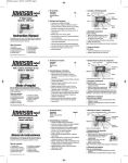
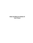
ISP1763A PCI evaluation board UM0865 User manual Abstract This document describes board level operations of the ISP1763A PCI evaluation board. Two version of the board are available: one for the TFBGA package and the other for the VFQFPN package. The ISP1763A PCI evaluation board allows engineers and software developers to create USB host, device, and OTG features for customer applications. Keywords isp1763a; usb; universal serial bus; host controller; otg; on-the-go CD00257207 Rev 3 2013-10-16 © Copyright ST. All rights reserved. ISP1763A ISP1763A PCI evaluation board User manual Legal information UM0865 Legal information Information in this document is provided solely in connection with ST products. STMicroelectronics NV and its subsidiaries (“ST”) reserve the right to make changes, corrections, modifications or improvements, to this document, and the products and services described herein at any time, without notice. All ST products are sold pursuant to ST’s terms and conditions of sale. Purchasers are solely responsible for the choice, selection and use of the ST products and services described herein, and ST assumes no liability whatsoever relating to the choice, selection or use of the ST products and services described herein. No license, express or implied, by estoppel or otherwise, to any intellectual property rights is granted under this document. If any part of this document refers to any third party products or services it shall not be deemed a license grant by ST for the use of such third party products or services, or any intellectual property contained therein or considered as a warranty covering the use in any manner whatsoever of such third party products or services or any intellectual property contained therein. UNLESS OTHERWISE SET FORTH IN ST’S TERMS AND CONDITIONS OF SALE ST DISCLAIMS ANY EXPRESS OR IMPLIED WARRANTY WITH RESPECT TO THE USE AND/OR SALE OF ST PRODUCTS INCLUDING WITHOUT LIMITATION IMPLIED WARRANTIES OF MERCHANTABILITY, FITNESS FOR A PARTICULAR PURPOSE (AND THEIR EQUIVALENTS UNDER THE LAWS OF ANY JURISDICTION), OR INFRINGEMENT OF ANY PATENT, COPYRIGHT OR OTHER INTELLECTUAL PROPERTY RIGHT. ST PRODUCTS ARE NOT DESIGNED OR AUTHORIZED FOR USE IN: (A) SAFETY CRITICAL APPLICATIONS SUCH AS LIFE SUPPORTING, ACTIVE IMPLANTED DEVICES OR SYSTEMS WITH PRODUCT FUNCTIONAL SAFETY REQUIREMENTS; (B) AERONAUTIC APPLICATIONS; (C) AUTOMOTIVE APPLICATIONS OR ENVIRONMENTS, AND/OR (D) AEROSPACE APPLICATIONS OR ENVIRONMENTS. WHERE ST PRODUCTS ARE NOT DESIGNED FOR SUCH USE, THE PURCHASER SHALL USE PRODUCTS AT PURCHASER’S SOLE RISK, EVEN IF ST HAS BEEN INFORMED IN WRITING OF SUCH USAGE, UNLESS A PRODUCT IS EXPRESSLY DESIGNATED BY ST AS BEING INTENDED FOR “AUTOMOTIVE, AUTOMOTIVE SAFETY OR MEDICAL” INDUSTRY DOMAINS ACCORDING TO ST PRODUCT DESIGN SPECIFICATIONS. PRODUCTS FORMALLY ESCC, QML OR JAN QUALIFIED ARE DEEMED SUITABLE FOR USE IN AEROSPACE BY THE CORRESPONDING GOVERNMENTAL AGENCY. Resale of ST products with provisions different from the statements and/or technical features set forth in this document shall immediately void any warranty granted by ST for the ST product or service described herein and shall not create or extend in any manner whatsoever, any liability of ST. ST and the ST logo are trademarks or registered trademarks of ST in various countries. Information in this document supersedes and replaces all information previously supplied. The ST logo is a registered trademark of STMicroelectronics. All other names are the property of their respective owners. © 2013 STMicroelectronics - All rights reserved STMicroelectronics group of companies Australia - Belgium - Brazil - Canada - China - Czech Republic - Finland - France - Germany - Hong Kong - India - Israel - Italy - Japan - Malaysia - Malta - Morocco - Philippines - Singapore - Spain - Sweden - Switzerland - United Kingdom - United States of America www.st.com CD00257207 Rev 3 2013-10-16 © Copyright ST. All rights reserved. ISP1763A 2 (29) ISP1763A PCI evaluation board User manual Contents UM0865 Contents 1 About this document 5 1.1 Purpose 5 1.2 Revision information 5 1.3 Board history 5 1.4 Reference list 5 2 Introduction 6 2.1 Key features 6 2.2 Basic operation 8 2.2.1 Working with Linux OS 8 2.2.2 Working with Windows CE OS 8 3 Physical description 9 3.1 Board layout 9 3.2 Connectors 9 3.2.1 J1 PLX signals probe connector 10 3.2.2 J2 ISP1763A bus interface 10 3.2.3 J3, J4, J5, and J6 bus test headers 11 3.2.4 USB ports 11 3.2.5 JP1 Xilinx 3-state input 11 3.2.6 JP2 Xilinx PROG input 11 3.2.7 JP3 Xilinx JTAG connector 11 3.2.8 JP4 GND connector 12 3.2.9 JP5 GND connector 12 3.2.10 JP6 +5 V power select 12 3.2.11 JP7 VCC(I/O) select 12 3.2.12 PS1 PC power connector 12 3.2.13 PS2 DC power socket 12 3.2.14 CON1 PCI connector 12 3.2.15 CN1 PXA320 platform connector 12 3.2.16 DC1 DM357platform connector 13 3.2.17 Conf1* butterfly configuration 13 CD00257207 Rev 3 2013-10-16 © Copyright ST. All rights reserved. ISP1763A 3 (29) ISP1763A PCI evaluation board User manual Contents UM0865 3.3 LEDs 14 3.4 Board components 15 3.4.1 ISP1763A chip 15 3.4.2 PLX9054 and 93LC56C EEPROM 16 3.4.3 Xilinx XC3S500E 17 4 Schematics 18 5 List of materials 25 Glossary CD00257207 29 Rev 3 2013-10-16 © Copyright ST. All rights reserved. ISP1763A 4 (29) ISP1763A PCI evaluation board User manual About this document UM0865 1 About this document 1.1 Purpose This document provides description on how to use the evaluation module to develop software for customers. 1.2 Revision information Table 1 Revision history Date Rev. Comments 2010-02-12 1 First release. 2010-04-05 2 Updated the last paragraph of Section 3.2.3 and Section 3.2.7. Changed the package name from HVQFN to VFQFPN. 2013-10-16 1.3 Applied ST branding. No other change in the content. Board history 1.4 CD00257207 3 Table 2 Board history Date Rev. Comments 2009-10-30 09283-1 ISP1763 PCI evaluation board (TFBGA) first release. 2009-10-30 09282-1 ISP1763 PCI evaluation board (VFQFPN) first release. Reference list Rev 3 [1] Universal Serial Bus Specification Rev. 2.0 [2] PCI Local Bus Specification Version 2.2 [3] PLX PCI 9054 Data Sheet [4] ISP1763A PCI evaluation board - FPGA design (UM0887) CD00259895 [5] ISP1763A Hi-Speed USB OTG controller data sheet CD00264885 [6] ISP1763A programming guide (PM0070) CD00265095 2013-10-16 © Copyright ST. All rights reserved. www.usb.org ISP1763A 5 (29) ISP1763A PCI evaluation board User manual Introduction UM0865 2 Introduction This section provides a description of the ISP1763A PCI evaluation board along with the key features and a block diagram of the circuit board. 2.1 Key features The ISP1763A is a Hi-Speed Universal Serial Bus (USB) On-The-Go (OTG) dual-role controller with two USB ports. Port 1 is configurable as a host controller, an OTG controller, or a peripheral controller, while port 2 is always assigned to the host controller. The ISP1763A bus interface provides SRAM, general-multiplex, NOR, and NAND modes to communicate with most types of microcontrollers and microprocessors. The PCI bridge board allows you to demonstrate the functionality of the ISP1763A on a standard PC with at least one PCI slot. ISP1763A POWER 1.8 V SUPPLY XILINX JTAG 2.5 V SUPPLY 3.3 V SUPPLY PLX9054 EEPROM PCI CONNECTOR Figure 1 Block diagram of the ISP1763A PCI evaluation board Key features include: CD00257207 Rev 3 12 MHz crystal clock input One OTG port, one host only port Four types of bus interfaces FPGA configuration PCI connection Multiple voltage power supply 2013-10-16 © Copyright ST. All rights reserved. ISP1763A 6 (29) ISP1763A PCI evaluation board User manual Introduction UM0865 CD00257207 Rev 3 All local bus signals are easily accessible on test headers designed for direct connection of a standard Tektronix logic analyzer Figure 2 ISP1763A PCI evaluation board—VFQFPN Figure 3 ISP1763A PCI evaluation board—TFBGA 2013-10-16 © Copyright ST. All rights reserved. ISP1763A 7 (29) ISP1763A PCI evaluation board User manual Introduction UM0865 2.2 Basic operation Any x86-based computer that has a PCI slot (32-bit, 33 MHz) running with Linux Red Hat kernel can be used. The type of Linux Red Hat installation determines minimum system requirements. The minimum recommended system configuration is a Pentium-class processor (1 GHz) with 128 MB RAM. An x86-based computer that has an available PCI slot (32-bit, 33 MHz) running Windows CE ver. 5.0 or ver. 6.0 OS can be used. For STMicroelectronics set-up example, use Gigabyte GA-945GZM-S2 motherboard (on board Ethernet controller disabled) with RealTek PCI Ethernet card (PCI vendor ID is 10ECh and device ID is 8139h), and a standard 1.44 MB floppy disk drive (for system boot up). Follow this hardware configuration as much as possible, especially the motherboard and the Ethernet card. CD00257207 Rev 3 2013-10-16 © Copyright ST. All rights reserved. ISP1763A 8 (29) ISP1763A PCI evaluation board User manual Physical description UM0865 3 Physical description This section describer the physical layout of the ISP1763A PCI evaluation board and its interface. 3.1 Board layout The ISP1763A PCI evaluation board is 150 x 101.6 mm six-layer (TFBGA) or four-layer (VFQFPN) printed-circuit board that is powered by the PCI slot power. Figure 4 shows the layout of the top view of the ISP1763A PCI evaluation board. J6 JP3 JP1 U3 JP2 PS1 PS2 JP7 PORT1 U6 JP6 J1 PORT2 J3 Figure 4 3.2 J5 J2 U4 U1 U2 JP5 ISP1763A PCI evaluation board - top view Connectors These connectors and jumpers are described in the following sections. Table 3 CD00257207 Rev 3 Connectors Connector Function J1 PLX signals probe connector 1 2013-10-16 © Copyright ST. All rights reserved. ISP1763A 9 (29) ISP1763A PCI evaluation board User manual Physical description UM0865 Connector Function J2 ISP1763A bus interface J3 Bus test header. Lower 8-bit AD bus. J4 Bus test header. Control signal of the ISP1763A. J5 Bus test header. Upper 8-bit AD bus. J6 Bus test header. 8-bit address bus. S3 / port 1 Micro-AB USB connector. S2 / port 2 Standard-A USB connector. JP1 Xilinx Tristate input. Tristate input to Xilinx to 3-state signals to the ISP1763A. JP2 Xilinx PROG input. When this jumper is connected, the FPGA code will be loaded to Xilinx from U5. JP3 Xilinx JTAG connector JP4 GND connector JP5 GND connector JP6 +5 V power select JP7 VCC(I/O) select PS1 PC power connector PS2 DC power socket CON1 PCI connector CN1 PXA320 platform connector DC1 DM357 platform connector Conf1* Butterfly configuration This is only for using the logic analyzer. Probe debug signals between FPGA and PLX9054 communication. The default setting is not mounted on board. This header has all the address bus, data bus, and control signals of the ISP1763A. CD00257207 Rev 3 2013-10-16 © Copyright ST. All rights reserved. ISP1763A 10 (29) ISP1763A PCI evaluation board User manual Physical description UM0865 Figure 5 J2 bus interface These headers are only used to probe bus interface signals. Only for testing. The J3 male header is for lower 8-bit AD[7:0] signals. The J5 male header is for upper 8-bit AD[15:8] signals. The J4 male header is for the DACK, DREQ, IRQ, CLE, ALE/ADV_N, WR_N/RW_N/WE_N, RD_N/DS_N/RE_N/OE_N, and CS_N/CE_N control signals. The J6 male header is for 8-bit A[7:0] signals. The ISP1763A has two ports. Port 1 can be configured as either the host controller or the peripheral controller. Has a micro-AB USB connector on board. Port 2 is configured as the host controller. Has a standard-A USB host connector on board. This is the 3-state input to Xilinx. Connect pin 1 and pin 2. The Xilinx pins connected to the ISP1763A are not 3-stated. Connect pin 3 and pin 2. The Xilinx pins connected to the ISP1763A are 3-stated. This is the Xilinx PROG input. When this jumper is connected, the FPGA code will be loaded to Xilinx from U5. Figure 6 JP3 JTAG connector Through the JTAG interface, download program into Xilinx XC3S500E. Use the Xilinx USB blaster to connect the JTAG interface on board. LED1 turns on when FPGA successfully completes configuration. CD00257207 Rev 3 2013-10-16 © Copyright ST. All rights reserved. ISP1763A 11 (29) ISP1763A PCI evaluation board User manual Physical description UM0865 The GND connector is to connect the oscilloscope or logic analyzer probe. The GND connector is to connect the oscilloscope or logic analyzer probe. This is the 5 V power supply select. Connect pin 1 and pin 2. 5 V is supplied by external power supply PS1 or PS2. Connect pin 2 and pin 3. 5 V is supplied by the PCI slot (default). This is the VCC(I/O) power supply select. Connect pin 1 and pin 2. VCC(I/O) is powered by 3.3 V (default). Connect pin 2 and pin 3. VCC(I/O) is powered by 1.8 V. Used for external supply of +12 V from the PC power supply. Connect pin 1 and pin 2 of JP6. 5 V is supplied by external power supply PS1. This is not used when the ISP1763A is inserted into the PCI slot. Used for the external supply of +12 V / 3 A from the DC power supply. Connect pin 1 and pin 2 of JP6. 5 V is supplied by external power supply PS2. This is not used when the ISP1763A is inserted into the PCI slot. This is the standard PCI bus interface that is compliant with PCI Local Bus Specification Ver. 2.2. All PCI signals are connected to PLX9054 PCI-to-local bus I/O accelerator chip. By default, this connector is not mounted. Only for the BSQUARE PXA320 platform use. While using this connector with the PXA320 platform, the ISP1763A PCI evaluation board is powered by external DC +12 V / 3 A power supply PS2. 1. Connect pin 1 and pin 2 of jumper JP6. The evaluation board is powered by the external power supply. CD00257207 Rev 3 2013-10-16 © Copyright ST. All rights reserved. ISP1763A 12 (29) ISP1763A PCI evaluation board User manual Physical description UM0865 2. Connect pin 1 and pin 2 of jumper JP7. The I/O voltage of the ISP1763A is set at 3.3 V. The PXA320 platform does not provide 1.8 V. 3. Connect pin 2 and pin 3 of jumper JP1. It 3-states all I/O pins from the FPGA connected to the ISP1763A IC. 4. Connect pin 1 and pin 2 of jumper JP2. The FPGA program is loaded from U5. The program has the logic for the 3-state of the pins. By default, this connector is not mounted. Only for the DAVINCI DM357 platform use. While using this connector with the DM357 platform, the ISP1763A PCI evaluation board is powered by external DC +12 V / 3 A power supply PS2. 1. Connect pin 1 and pin 2 of jumper JP6. The evaluation board is powered by the external power supply. 2. Connect pin 2 and pin 3 of jumper JP7. The I/O voltage of the ISP1763A is set at 1.8 V. The DM357 platform does not provide 3.3 V. 3. Connect pin 2 and pin 3 of jumper JP1. It 3-states all I/O pins from the FPGA connected to the ISP1763A IC. 4. Connect pin 1 and pin 2 of jumper JP2. The FPGA program is loaded from U5. The program has the logic for the 3-state of pins. Frequency selection is done using pins FREQSEL1 and FREQSEL2. The corresponding resistors are mounted to connect FREQSEL1 and FRESEL2 to GND or VCC(I/O). To connect FREQSEL2 to LOW, mount R111 and remove R113. To connect FREQSEL2 to HIGH, mount R113 and remove R111. To connect FREQSEL1 to LOW, mount R112 and remove R114. To connect FREQSEL1 to HIGH, mount R114 and remove R112. The PIO mode selection is needed only for the actual platform validation. On the x86 platform, PIO mode selection is done using the Xilinx FPGA code. The mounting of resistors (R119 to R122) do not affect the mode selection done by Xilinx. To configure in various modes, refer to ISP1763A PCI evaluation board - FPGA design (UM0887). When the ISP1763A is connected to customer platform, mode selection is done using pins CLE and ALE/ADV_N. The corresponding resistors are mounted to connect CLE and ALE/ADV_N to GND or VCC(I/O). CD00257207 Rev 3 To connect CLE to LOW, mount R120 and remove R122. To connect CLE to HIGH, mount R122 and remove R120. To connect ALE/ADV_N to LOW, mount R119 and remove R121. To connect ALE/ADV_N to HIGH, mount R121 and remove R119. 2013-10-16 © Copyright ST. All rights reserved. ISP1763A 13 (29) ISP1763A PCI evaluation board User manual Physical description UM0865 Figure 7 Table 4 Butterfly configuration Clock frequency and bus interface configuration Clock frequency 12 MHz (default) 19.2 MHz 24 MHz Reserved Comment FREQSEL2 LOW LOW HIGH HIGH Through R111 to GND. Through R113 to VCC(I/O). FREQSEL1 LOW HIGH LOW HIGH Through R112 to GND. Through R114 to VCC(IO). Bus interface SRAM (default) NAND NOR General multiplex Comment CLE HIGH LOW LOW HIGH Through R120 to GND. Through R122 to VCC(I/O). ALE/ADV_N HIGH LOW HIGH LOW Through R119 to GND. Through R121 to VCC(I/O). 3.3 LEDs The ISP1763A PCI evaluation board has seven LEDs that are located on the top side of the board. Information regarding these LEDs is given in Table 5. Table 5 LED LED Use Color LED1 JTAG download or program done indicator Orange LED2 VBUS2 volts indicator (After loading the host software, the light will be turned on.) Red LED3 VBUS1 volts indicator (After loading the host software, the light will be turned on.) Red CD00257207 Rev 3 2013-10-16 © Copyright ST. All rights reserved. ISP1763A 14 (29) ISP1763A PCI evaluation board User manual Physical description UM0865 LED Use Color LED4 +5 V indicator Blue LED5 +1.8 V indicator Red LED6 +2.5 V indicator Yellow LED7 +3.3 V indicator Green 3.4 Board components This describes the operation of the major board components on the ISP1763A PCI evaluation board. The ISP1763A PCI evaluation board is available in two packages: TFBGA and VFQFPN. CD00257207 Rev 3 Figure 8 ISP1763A VFQFPN Figure 9 ISP1763A TFBGA 2013-10-16 © Copyright ST. All rights reserved. ISP1763A 15 (29) ISP1763A PCI evaluation board User manual Physical description UM0865 Table 6 ISP1763A chip package information Product Package Package description ISP1763AETTM TFBGA64 64 balls; body 4 × 4 × 0.8 mm ISP1763AHNTM VFQFPN64 64 terminals; body 9 × 9 × 1.0 mm For the schematic design, there is no difference, except the chip footprint. For the PCB layout, TFBGA is six-layered design whereas VFQFPN is only four-layered design. All the components are same on both the boards, except the ISP1763A IC package. PLX9054 is a PCI-to-local-bus accelerator. The ISP1763A is always a PCI target during initialization, as well as during the data transfer phase to or from the ISP1763A memory. Figure 10 PLX9054 When powering on or asserting the PCI_RESET signal, PLX9054 attempts to read the serial EEPROM to check its presence. The 93LC56C EEPROM is required for the correct initialization of PLX9054. The serial EEPROM contains information required to initialize PLX9054 registers. For details, refer to Chapter 11 of PLX PCI 9054 Data Sheet. The initial programming of 93C56 must be done in a serial EEPROM programmer. Displaying and adjusting of certain parameters can be done using the PLXmon utility. CD00257207 Rev 3 2013-10-16 © Copyright ST. All rights reserved. ISP1763A 16 (29) ISP1763A PCI evaluation board User manual Physical description UM0865 Figure 11 EEPROM 93C56 FPGA ensures adaptation between the ISP1763A generic bus interface and the PLX9054 local bus interface. The FPGA programming can be downloaded through the JTAG interface. Figure 12 Xilinx XC3S500E For detail description of the FPGA programming, refer to ISP1763A PCI evaluation board - FPGA design (UM0887). CD00257207 Rev 3 2013-10-16 © Copyright ST. All rights reserved. ISP1763A 17 (29) ISP1763A PCI evaluation board User manual Schematics UM0865 4 Schematics Figure 13 CD00257207 Rev 3 2013-10-16 © Copyright ST. All rights reserved. Main ISP1763A 18 (29) ISP1763A PCI evaluation board User manual Schematics UM0865 Figure 14 CD00257207 ISP1763A Rev 3 2013-10-16 © Copyright ST. All rights reserved. ISP1763A 19 (29) ISP1763A PCI evaluation board User manual Schematics UM0865 Figure 15 CD00257207 USB ports Rev 3 2013-10-16 © Copyright ST. All rights reserved. ISP1763A 20 (29) ISP1763A PCI evaluation board User manual Schematics UM0865 Figure 16 CD00257207 FPGA Rev 3 2013-10-16 © Copyright ST. All rights reserved. ISP1763A 21 (29) ISP1763A PCI evaluation board User manual Schematics UM0865 Figure 17 CD00257207 PCI Rev 3 2013-10-16 © Copyright ST. All rights reserved. ISP1763A 22 (29) ISP1763A PCI evaluation board User manual Schematics UM0865 Figure 18 CD00257207 Power Rev 3 2013-10-16 © Copyright ST. All rights reserved. ISP1763A 23 (29) ISP1763A PCI evaluation board User manual Schematics UM0865 Figure 19 CD00257207 Connectors Rev 3 2013-10-16 © Copyright ST. All rights reserved. ISP1763A 24 (29) ISP1763A PCI evaluation board User manual List of materials UM0865 5 Table 7 List of materials List of materials Part type Designator Footprint Description 0Ω R80, R81, R83, R82, R77, R76, R79, R78, R93, R92, R95, R94, R85, R84, R91, R90, R75, R64, R63, R66, R65, R39, R38, R62, R61, R72, R71, R74, R73, R68, R67, R70, R69, R155, R148, R162, R158, R149, R146, R153, R150, R167, R166, R160, R168, R164, R161, R165, R163, R145, R89, R88, R123, R109, R97, R96, R98, R99, R138, R126, R140, R139, R133, R124, R132, R134, R3, R2, R1, R45, R46, R24 R0603 Resistor SMD 0603 1/16W 1% 0 Ω, lead free 1 kΩ R25, R37, R26, R9, R8, R14, R15, R16, R36, R17 R0603 Resistor SMD 0603 1/10W 1% 1 kΩ lead free 2 kΩ R156 R0603 Resistor SMD 0603 1/10W 1% 2 kΩ, lead free 3 kΩ R157 R0603 Resistor SMD 0603 1/16W 1% 3 kΩ, lead free 3Ω R147 R0603 Resistor SMD 0603 1/10W 1% 3 Ω, lead free 4.7 kΩ R107, R110, R106, R101 R0603 Resistor SMD 0603 1/10W 1% 4K7 lead free 4.7 µF C108, C112 TAN SMD-A Capacitor tan SMD-A 4u7F/10 V +/-20%, lead free 4.7 µF C96, C97 C0603 Capacitor SMD 0603 4u7F/10 V Y5V +80%-20%, lead free 4.7 µF C117 ELE SMD-B Capacitor Ele SMD-B 4u7F/35 V +/-20%, lead free 10 kΩ R59, R60, R57, R56, R58, R43, R118, R44, R130, R49, R47, R117, R55, R111, R42, R121, R113, R50, R114, R112, R52, R53, R54, R51, R119, R122, R120, R6, R7, R143, R5, R12, R135, R10, R11, R41, R40, R34, R35, R159, R48, R4, R22, R32, R27, R28, R29, R131, R33, R127, R30, R18, R19, R129, R128, R23, R31, R20, R21 C0603 Resistor SMD 0603 1/16W 1% 10 kΩ lead free 10 nF C80, C75, C70, C104, C42, C37, C65, C45, C40, C35, C60, C55, C50, C102, C82, C77, C72, C106, C98, C100,C52, C47, C57, C67, C62, C24, C12, C14, C26, C10, C30, C28, C8, C4, C2,C22, C20, C6, C16, C18 C0603 Capacitor SMD 0603 10 nF/50 V 10% X7R 10 Ω R147 C0603 Resistor SMD 0603 1/16W 1% 10 Ω, lead free CD00257207 Rev 3 2013-10-16 © Copyright ST. All rights reserved. ISP1763A 25 (29) ISP1763A PCI evaluation board User manual List of materials UM0865 Part type Designator Footprint Description 10 µF C128, C130, C120, C127, C129, C134, C132, C131 ELE SMD-B Capacitor Ele SMD-B 10uF/25 V +/-20%, lead free 12 kΩ R115, R116 C0603 Resistor SMD 0603 1/16W 1% 12 kΩ, lead free 15 pF C94 C0603 Capacitor SMD 0603 15 pF/50 V 5%, lead free 18 pF C110, C111 C0603 Capacitor SMD 0603 18 pF / 50 V 5% 22 Ω R86, R87 C0603 Resistor SMD 0603 1/16W 1% 22 Ω, lead free 22 µF C133 TAN SMD-D Capacitor tan SMD-D 22 µF/25 V +/-20%, lead free 33 kΩ R141 C0603 Resistor SMD 0603 1/16W 1% 33 kΩ, lead free 33 Ω R154 C0603 Resistor SMD 0603 1/16W 1% 33 Ω lead free 51 Ω R152 C0603 Resistor SMD 0603 1/16W 1% 51 Ω, lead free 68 Ω R100 C0603 Resistor SMD 0603 1/16W 1% 68 Ω 100 kΩ R136 C0603 Resistor SMD 0603 1/10W 1% 100 kΩ lead free 100 nF C61, C23, C51, C21, C15, C56, C66, C49, C59, C76, C58, C71, C68, C63, C46, C19, C34, C44, C36, C64, C41, C39, C11, C73, C69, C74, C13, C78, C79, C33, C38, C5, C7, C48, C53, C9, C43, C17, C54, C25, C31, C29, C3, C1, C27, C95, C81, C87, C88, C83, C85, C86, C92, C84, C93, C89, C90, C91 C0603 Capacitor SMD 0603 100 nF/50 V +80-20%, lead free 100 nF C126, C125, C121, C122, C115, C118, C101, C103, C107, C99, C105, C123, C116, C113, C109 C0603 Capacitor SMD 0603 100 nF/50 V 10%, lead free 100 pF C32 C0603 Capacitor SMD 0603 100 pF/50 V 5% NPO 100 Ω R103, R102, R105, R104 C0603 Resistor SMD 0603 1/10W 1% 100 Ω lead free 100 µF C114 ELE SMD-D Capacitor Ele SMD-D 100 µF/16 V 20%, lead free 120 Ω R108 C0603 Resistor SMD 0603 1/10W 1% 120 Ω lead free 200 Ω R144 C0603 Resistor SMD 0603 1/16W 1% 200 Ω, lead free 220 µF C124 ELE SMD-E Capacitor Ele SMD 220 µF/10 V FK series, low ESR, +/-20%, lead free 240 Ω R151 C0603 Resistor SMD 0603 1/8W 1% 240 Ω, lead free CD00257207 Rev 3 2013-10-16 © Copyright ST. All rights reserved. ISP1763A 26 (29) ISP1763A PCI evaluation board User manual List of materials UM0865 Part type Designator Footprint Description 510 Ω R13 C0603 Resistor SMD 0603 1/10W 1% 510 Ω lead free 560 Ω R125, R137 C0603 Resistor SMD 0603 1/16W 1% 560 Ω, lead free 767130-1 J1 767130-1 Connector recept 38Pos 0.025CL 767130-1 B3S-1000 SW1 B3S-1000 Switch tact SMD 6 mm x 6 mm white BLM31A260S FB1, FB2 R1206 Murata ferrite bead, 1206 case, 0.05 Ω DC resistance CDRH104RNP7R0NC L1 CDRH104RNP Inductor SMD 7 µH/4.5 A DR1040-7R0-R CS10 12.000MABJ- X2 UT CS10 Crystal 12 MHz 6 x 3.5 mm CS10-12.000MABJ-UT DC power socket 2.5 mm DIA PS2 DC power socket Socket DC jack 2.5 mm PCB Mt DP04PR PS1 DP04PR Power disk drive RA 4-way FD2X20_LF J2 FD2X20 Connector PCB Mt 0.100" 2 x 20-way FDS8958A U13 SOIC-8_4 x 5 mm Transistor FDS8958A NP SO8 Header1 x 2_LF JP2, JP4, JP5 Header1 x 2 Header pin 0.100" 1 x 2-way gold, lead free Header1 x 3_LF JP1, JP6, JP7 Header1 x 3 Header pin 0.100" 1 x 3-way gold, lead free Header1 x 6_LF JP3 Header1 x 6 Header pin 0.100" 1 x 6-way gold, lead free Header2 x 8_LF J3, J4, J5, J6 Header2 x 8 Header pin 0.100" 2 x 8-way gold, lead free ISP1763 VFQFPN U6 VFQFPN-64 - LD1086D2T18TR U16 D2PAK IC reg LDO POS 1.8 V 1.5 A D2PAK LD1086D2T25TR U15 D2PAK IC reg LDO POS 2.5 V 1.5 A D2PAK LD1086D2T33TR U17 D2PAK IC reg LDO positive 3.3 V D2PAK LD1117S12TR U14 SOT-223 IC reg LDO POS 800MA 1.2 V SOT223 LED blue 0603_LF LED4 LED0603 LED blue 0603 LED green 0603, SML312ECT LED7 LED0603 Chip LED, green, SMD, 0603 package, 0.8 x 1.6 x 0.8 mm LED orange 0603_LF LED1 LED0603 LED orange 0603 LED red 3MM_LF LED2, LED3 LED3mm LED 3 mm red diffused LED red 0603_LF LED5 LED0603 LED red 0603 LED yellow 0603_LF LED6 LED0603 LED yellow 0603 CD00257207 Rev 3 2013-10-16 © Copyright ST. All rights reserved. ISP1763A 27 (29) ISP1763A PCI evaluation board User manual List of materials UM0865 Part type Designator Footprint MAX1791EUB+ U12 MSOP-10_3 x 3 mm IC MAX1791EUB+ MIC2026-2 U8 SOIC-8_4 x 5 mm IC MIC2026-2YM PCI9054 U2 F-QFP176/P.5N - SFM-150-02-S-D-A CN1 SFM-150-02-S-D-A Connector SMT 0.5" 2x50 SFM-150-02-S-D-A SMB PCB VERT S1 SMB SMB jack 50 Ω PCB Mt ST SN74LVT244BPW U4 TSSOP20_4.4 x 6.5 mm IC 74LVT244BPW 20-TSSOP SPXO018044 X1 SPXO018044 Oscillator 50.000 MHz HCMOS 3.3 V 1/2 size Test point 1.8 TPREQ#1, TPGNT#1, TP11, TP12, TP13, TP10, TP7, TP6, TP9, TP4, TP1, TP2, TP3, TP8, TP5 TP18 Test point TFM-135-32-S-D-A DC1 TFM-135-32-S-D-A Samtec connector SMT, vertical, plug, 35 x 2, TFM135-32-S-D-A USB con type A receptacle S2 USB_A USB type A RA 4-way 875200010B USBULC6-2F3 U7, U9, U10, U11 USBULC6-2F3 ESD protection diode USB_AB_MICRO S3 USB micro type AB Micro USB type AB SMD R/A ZX62-AB-5P XC3S500E U3 PQ208 IC Spartan XC3S500E4PQG208C PQFP XCF04S U5 TSSOP20_4.4 x 6.5 mm IC programmable XCF04SVOG20C 20-TSSOP u93LC56C U1 DIP8 IC 93LC56C-I/P, EEPROM DIP-8, lead free CD00257207 Rev 3 2013-10-16 © Copyright ST. All rights reserved. Description ISP1763A 28 (29) ISP1763A PCI evaluation board User manual Glossary UM0865 Glossary EEPROM Electrically Erasable Programmable Read-Only Memory FPGA Field-Programmable Gate Array NAND Not AND NOR Nor OR OS Operating System OTG On-The-Go PCI Peripheral Component Interconnect PIO Parallel Input/Output RAM Random-Access Memory SRAM Static Random Access Memory USB Universal Serial Bus CD00257207 Rev 3 2013-10-16 © Copyright ST. All rights reserved. ISP1763A 29 (29)