1
ALICE/2000-19
Internal Note/DAQ
20 July 2000
Assessment of
VME-PCI Interfaces
with Linux drivers
This report summarizes the performance measurements and experiences made by
testing three commercial VME-PCI interfaces with their Linux drivers. These
interfaces are manufactured by Wiener, National Instruments, and SBS Bit 3. The
developed C programs are reading/writing a VME memory in different transfer
modes via these interfaces. A dual processor HP Kayak XA-s workstation was
used with the CERN certified Red Hat Linux 6.1 running on it.
1
Introduction . . . . . . . . . . . . . . . . . . . . . . . . 2
2
Wiener PCIVME Link . . . . . . . . . . . . . . . . . . 5
3
National Instruments VME-PCI8026 Kit . . . . . . . . 9
4
SBS Bit 3 Model 617 Adapter . . . . . . . . . . . . . 19
5
Summary . . . . . . . . . . . . . . . . . . . . . . . . 27
Issue:
Revision:
Final
3
Reference:
Created:
Last Modified:
Assessment of VME-PCI Interfaces with Linux drivers
13 April 2000
20 July 2000
Prepared by:
Klaus Schossmaier, CERN - EP/AID
2
Assessment of VME-PCI Interfaces with Linux drivers
1 Introduction
TheVMEbus and PCI bus are both well proven technologies with there own
application areas. However, there are good reasons to bridge them by an VME-PCI
interface. First, if the main application runs on the VMEbus, it can be useful to
monitor and control it by a PCI-based computer. Second, since VMEbus equipment
is rather expensive, such an interface can provide access to usually cheaper PCI
system resources (e.g. processors, memory, disks). Last but not least, such interfaces
help to make a migration between these technologies more easily. In fact, several
VMEbus or PCI-based systems can be put together to a network with the help of
such interfaces. Designing and crafting a VME-PCI interface remains a challenge,
see [1], since the busses have different structures concerning the protocol (VME:
asynchronous, PCI: synchronous), speed (VME: 40 MB/s, PCI: 132 MB/s),
endianness (VME: big, PCI: little), configuration and interrupt handling.
This report presents the usage and performance of three VME-PCI interfaces from
the companies Wiener, National Instruments, and SBS Bit 3 with their Linux
drivers. They are tested by reading/writing a VME memory. The report is
organized as follows: Chapter 1 describes the test setup, summarizes the goals of
the study, and explains the method how performance data was obtained.
Chapter 2, Chapter 3, and Chapter 4 are devoted to each one of these interfaces by
giving a short description, explaining the driver installation, and presenting the
performance measurements. The last Chapter 5 shows a table that summarizes the
key features of the three VME-PCI interfaces.
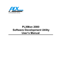
1.1 Test Setup
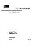
The following figure shows the test setup, which is composed of the VMEbus side
and the PCI bus side. An interface cable connects the two sides, which is usually a
few meters long. For convention, “reading” means in this report that data is moved
from the VMEbus side to the PCI bus side, and “writing” the other way around.
VMEbus
VMETRO analyzer
PCI bus
read
write
CPU
bridge
RAM
VMEbus memory
interface cable
VME interface board
VMEbus system
PCI interface board
PCI-based computer
Introduction
3
On the VMEbus side, a 5-slot crate was used to accommodate one of the VMEbus
interface cards, a VMEbus memory (MM-6390 with 32 MB, or PME 2SB with 2MB),
and the VMETRO VTB-325B analyzer. On the PCI bus side, a HP Kayak XA-s
400SERIE0203 workstation with a dual PII@400MHz was used with Phoenix 4.6
BIOS HK.11.09US. For the specifications of this PC browse the Web page [2]. The
CERN certified Red Hat Linux 6.1 was running on it with kernel 2.2.12-12, see the
Web page [3] for further information. The PCI interface board was plugged into one
of the 5 available PCI slots on the PC.
1.2 Assessment Goals
The goals of the assessment can be expressed by the following questions:
1. How to install and configure these interfaces?
- PCI interface board: jumpers, IRQ lines
- VME interface board: jumpers, system controller
- interface cable: type, length, connector
- Linux driver: kernel version, symmetric multi-processor (SMP)
- multi-hardware installation
2. How to program a test application?
- C library functions, system calls, utilities
- manuals, support
3. Which transfer modes are possible?
- reading/writing
- A16, A24, A32 addressing
- D8, D16, D32, D64 data width
- byte/word swapping
- Programmed I/O (PIO) transfer
- Direct Memory Access (DMA) transfer
- Memory Mapping (MM) transfer
- non-aligned access
- concurrent access
4. What is the performance of each transfer mode?
- seen on the VMEbus (bus cycles)
- seen from the program (timing of function calls)
1.3 Timing Measurements
The aim of the timing measurements on a VME-PCI interface is to produce a graph,
which displays the transfer length on the x-axis and the corresponding duration for
it on the y-axis, for the different transfer modes. The setup time and transfer rate
can be obtained from such a graph. For that purpose, test C programs were
developed to time the specific code segment (function calls or loop) that is actually
responsible for the data transfer. The timing results are logged in file timing.dat.
Each test run executes an other loop, where a random transfer length is picked, and
an inner loop, where 100 transfers of this length are carried out. Thus we are getting
100 timing results for a certain transfer length. The 10 smallest and the 10 largest
values are discarded, and the average of the remaining 80 values is used as
duration for this transfer length. The distribution of the duration over a certain
transfer length is not shown, since this is beyond the scope of the assessment.
4
Assessment of VME-PCI Interfaces with Linux drivers
The following Perl-script timing.perl computes these length-duration points
and puts them in file timing.plot:
1:
2:
3:
4:
5:
6:
7:
8:
9:
10:
11:
$filename = "timing.dat";
open(IN,"<$filename") || die "cannot open $filename";
$filename = "timing.plot";
open(OUT,">$filename") || die "cannot open $filename";
$loop_inner = 100;
$skip = 10;
while($line = <IN>) {
@col = split(/ /,$line);
$bytes = shift @col;
@times = sort { $a <=> $b} @col;
$sum = 0;
for ($i=1+$skip; $i<=($loop_inner-$skip); ++$i)
{$sum += $times[$i];}
$average = $sum / ($loop_inner - 2*$skip);
print OUT "$bytes $average \n";
}
print OUT "0.0 0.0 \n";
close(IN);
close(OUT);
Afterwards the following gnuplot-script timing.gnu transfers the lengthduration points in file timing.plot to the Postscript-file timing.ps that
contains the desired graph:
1:
2:
3:
4:
5:
6:
7:
8:
9:
set terminal postscript eps color "Times-Roman"
set output "timing.ps"
set format y "%.2f"
set grid
set title "VME-PCI interface ... using ... for ..."
set xlabel "bytes"
set ylabel "microseconds"
plot [][] "timing.plot" with points
exit
The next chapters will show several graphs produced in this way. Right away, it
should be pointed out that performance data depends significantly on the VMEbus
device. For example, a too slow VMEbus memory can spoil the performance
measurements of a VME-PCI interface.
The timing results were checked with the measurements taken by the VMETRO
analyzer. They are presented be a table showing the access time, address modifier
(AM), VMEbus address, data, size, cycle and throughput in MB/s.
1.4 Acronyms
The following acronyms are frequently used throughout the document:
IRQ = interrupt request
SMP = symmetric multi-processor
PIO = programmed I/O
DMA = direct memory access
MM = memory mapping
AM = address modifier
MB/s = megabyte/second
Wiener PCIVME Link
5
2 Wiener PCIVME Link
2.1 Description
The Wiener PCIVME link consists of a single-slot VMEbus card (called VMEMM)
and a PCI card (called PCIADA). They are connected by a up to 10 meters SCSI-2
cable. Users get direct access to the VMEbus with A16/24/32 addressing and
D8/16/32 transfer size. Further information about the hardware and configuration
of the Wiener PCIVME link can be found at the Web page [4]. The product comes
only with drivers for Windows 95/NT, but [5] has developed drivers for the Linux
operation system. In my setup the arwvme.1.46 driver (initially arwvme.1.43)
was used. In the following the installation procedure and the performance results
will be presented. It is worth noting that there is no US ban on this product.
2.2 Driver Installation
1. Login as root
2. Download the driver:
http://www-ik3.fzk.de/~mathes/software/arwvme.1.46.tar.gz
into /usr/local
3. Unpack the archive:
# cd /usr/local
# tar vxfz arwvme.1.46.tar.gz
# mv arwvme arwvme-1.46
# cd arwvme-1.46/driver
4. Edit the Makefile (if necessary):
modify KERNEL_HDRS = /usr/local/include/linux
modify # DEFINES += -DUSE_ISA_MAPPING
modify # DEFINES += -DDEBUG
modify /sbin/depmod -a
modify /sbin/rmmod -a
5. Compile the kernel module:
# make
# make install
Check: # ls -l /dev/arw*
6. Load the kernel module:
# mv arwvme.o arwvme-1.46
# /sbin/insmod arwvme-1.46
Check: # /sbin/lsmod
Check: # tail -50 /var/log/messages
Check: # cat /proc/pci
7. Installing the library:
# cd /usr/local/arwvme-1.46
# xmkmf
# make depend
# make
8. Simple tests:
6
Assessment of VME-PCI Interfaces with Linux drivers
# cd /usr/local/arwvme-1.46
# test_mix
# test_map
When loading the driver, make sure that both cards (PCIADA and VMEMM) are in
operation and that the SCSI cable is in place. Keep in mind that the PCIADA board
cannot share PCI interrupts, thus a proper PCI interrupt assignment at boot-time
must be achieved. In general, this problem is alleviated if the Linux kernel is in
SMP mode. However, an attempt to compile the driver under an SMP kernel with a
properly modified Makefile failed. In any case, at compilation there will be a few
warnings, which can be ignored. A data transfer is indicated by the flashing LEDs.
Ignore any SYSFAIL LEDs on other VMEbus boards, since they will be cleared
when the interface is used for the first time. Make sure that the VMEMM is
operated as VMEbus master by setting the SC jumpers, since in my setup it did not
work as VMEbus slave. When the interface is plugged in and the PC boots (or on
other occasions, which could not be specified), a VMEbus reset might be triggered.
Another shortcoming is the fact, that there is no Makefile template provided for
user programs, thus all test programs were running as root.
If the interface is not responding after the above checks, it may become necessary to
remap the PCIVME access addresses from below 1 MB to high addresses. This can
be done with the PLXMON tool, which is included on the CD-ROM (Version 1.1
ARW 6-99). It also offers a test under DOS (of course without the arwvme driver) to
check the connection between the two cards. Documentation of this tool can be
found on the Web page [6]. In my setup it was necessary to reprogram the PLX9050
chip with the help of this tool. The following instructions give you an example how
to use the PLXMON tool:
1. Make a MS-DOS-bootable disk.
2. Create a folder PLXMON and copy the files PLXMON.EXE, EEP50V.MON and
EEP50VH.MON into this folder.
3. Boot the PC in MS-DOS mode.
4. Change to folder PLXMON and start PLXMON.EXE.
5. Type in the following PLXMON commands:
At start-up the program shows a list of found PCI devices. A star indicates the
first found device with VenID:DevID equal 0x10b5:0x9050.
&pcr
This command shows an address list of the PCI configuration registers. Verify if
the entry at offset 0x02c equals to 0x11679050.
&read eep50vh.mon
This command changes the information stored in the configuration EEPROM.
To undo this reprogramming, use the file eep50v.mon.
&lcr 50 18054184
&pcr
&dw fedf6000;r
This command displays 0x80 bytes of memory starting at address 0xfedf6000.
Do not type the 0x prefix. If the protocol between PCIADA and VMEMM is
working, the pattern 1118 will appear. With the appended ;r the range of
memory is displayed repeatedly.
&q
Wiener PCIVME Link
7
2.3 Data Transfer
Only the PIO transfer was working in my setup with the provided C library
functions. Trying out memory mapping accesses had no effect on the VMEbus.
DMA or VME64 transfers are not supported by design. In the following the
programming, the VMEbus cycles and the timing of PIO writing/reading transfers
will be presented.
◆ Programming for PIO writing:
1: arwvme_fd = ArwvmeOpen(1);
2: ArwvmeSetMode (arwvme_fd,
ARWVME_A32|ARWVME_D32|ARWVME_DATA|ARWVME_NONPRIV);
3: lseek (arwvme_fd, address_vme, SEEK_SET);
4: ArwvmeWrite (arwvme_fd, buffer_pci, length);
5: ArwvmeShutdown(arwvme_fd);
◆ VMEbus cycles for PIO writing (16 KB length):
VMEbus • Wiener • writing A32D32 with PIO
Time
AM
Address
Data
Size
Cycle
MBytes/s
11 µs
09
32 bit
32 bit
LONG
WRI
0.37
◆ Programming for PIO reading:
1: arwvme_fd = ArwvmeOpen(1);
2: ArwvmeSetMode (arwvme_fd,
ARWVME_A32|ARWVME_D32|ARWVME_DATA|ARWVME_NONPRIV);
3: lseek (arwvme_fd, address_vme, SEEK_SET);
4: ArwvmeRead (arwvme_fd, buffer_pci, length);
5: ArwvmeShutdown(arwvme_fd);
◆ VMEbus cycles for PIO reading (16 KB length):
VMEbus • Wiener • reading A32D32 with PIO
Time
AM
Address
Data
Size
Cycle
3 µs
09
32 bit
32 bit
LONG
RD
MBytes/s
1.29
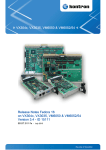
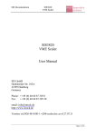
◆ Timing for PIO writing/reading:
The following graph displays the access times over the transfer lengths for both
PIO reading and writing. There exists a linear relation with a rather large variation
of the points. Roughly speaking, 0.3 MB/s with no setup time can be achieved for
PIO reading, and 1.1 MB/s with no setup time for PIO writing. This confirms also
the measurements taken by VMETRO.
8
Assessment of VME-PCI Interfaces with Linux drivers
WIENER PCIVME Link with arwvme-1.46 driver
100.00
"timing.WIENER.ArwvmeRead"
"timing.WIENER.ArwvmeWrite"
milliseconds
80.00
60.00
40.00
20.00
0.00
0
2
4
6
8
10
12
14
16
18
KB
◆ Access to non-existing VME address:
In case of a read or write access to an unused VMEbus address (no board in the
crate responds), the running program exits. This is not convenient for an
application that uses this interface, since it cannot be catched.
◆ Non-aligned access for PIO writing/reading:
If the start address is non-aligned, a BERR occurs, and if the length is non-aligned,
pre-reads are carried out. No further details are presented, since this issue would
only be of interest for DMA transfers.
◆ Concurrent access:
When several concurrent processes running on the PC try to access the Wiener
PCIVME link, only the first one can call function ArwvmeOpen()successfully.
Processes coming afterwards fail to do so. Hence only one process at a time can use
the interface. Note that calling function ArwvmeOpen() twice within the same
program also fails.
◆ Multi-hardware installation:
According to the manual, the driver allows an arbitrary number of PCIVME links,
however, besides the number of available PCI slots there is a limit of 16 due to the
VMEMM jumpers. The parameter in function ArwvmeOpen() determinates which
links will be used. In my setup only one link was tested.
National Instruments VME-PCI8026 Kit
9
3 National Instruments VME-PCI8026 Kit
3.1 Description
The NI VME-PCI8026 kit consists of a single-slot, double-height VMEbus device
(called VME-MXI-2) and a half-size PCI circuit board (called PCI-MXI-2). They are
connected by a MXI-2 cable with a maximum length of 20 meters. Users get direct
access to the VMEbus with A16/24/32 addressing and D8/16/32/64 transfer size.
More information about the VME-PCI8026 kit can be found in the manual [7] and
[8]. The product comes with a driver for Linux running kernel 2.2.x. In my setup I
was using version 1.6 of the driver (initially beta version 0.5). This driver provides
an interface to the NI-VXI library functions. Programming information about them
can be found in the manual [9] and [10]. In addition, LabVIEWTM can be used for
programming applications. In the following the installation procedure and the
performance results will be presented.
3.2 Driver Installation
1. Login as root
2. Download and unpack the driver:
# cd /afs/cern.ch/sw/natinst/drivers/pci-mxi/linux-1.6
# mkdir /usr/local/linux871
# cp linux871_mxi2.tgz /usr/local/linux871
# cd /usr/local/linux871
# tar xvzf linux871_mxi2.tgz
# rpm -ivh nivxi-pcimxi-1.6-1.i386.rpm
# rpm -ivh nivisa-2.0.1-2.i386.rpm
3. Compile the kernel module:
# cd /usr/local/nivxi/src
# make
4. Install shared libraries:
# echo ’/usr/local/nivxi/lib’ >> /etc/ld.so.conf
# /sbin/ldconfig
5. Load the kernel module:
# cd /usr/local/nivxi/sys
# mv vxi vxi-1.6
# ln -s vxi-1.6 vxi
# ./load_vxi
Check: # /sbin/lsmod
Check: # tail -50 /var/log/messages
Check: # cat /proc/pci
6. Loading the kernel module at boot time:
Add the command /usr/local/nivxi/sys/load_vxi in file
/etc/rc.d/rc.local.
Another way is to edit the file /etc/conf.modules accordingly.
7. Configure the VME devices (e.g. memory):
# cd /usr/local/nivxi/bin
# resman
10
Assessment of VME-PCI Interfaces with Linux drivers
# vxitedit
7 add vmeMemory 1 2 0 0 1 2MB Plessy 0 0 0xc00000 0x1fffff
0x03c00000 0x1fffff 0 0 1 save exit 12
# resman
Check: # vxitedit
type: 1 di exit 12
8. Simple test with VXIbus Text Interactive Control (victext):
# /usr/local/nivxi/bin/victext
vxiin 2,0xc00000,2
vxiout 2,0xc00000,2,0x1234
deviceinformation?
quit
Loading the kernel module usually works without problems, but removing it with
/usr/local/nivxi/sys/unload_vxi sometimes fails. In this case execute
/usr/local/nivxi/bin/vxiclean. This also helps when the resource
manager resman failed (e.g. driver busy) or hangs. You must run resman each
time the VME chassis power is cycled. The VXI driver has to be loaded before
resman can be executed. If VXI bus timeout settings are not properly set, resman
can be delayed (once I experienced around 30 seconds). By default the VME-MXI-2
card has logical address 1, which can be changed by the DIP switch. However,
using the VMEbus memory PME 2SB with 2MB, I needed to change it to 16,
otherwise resman did not succeed (error code 12). Since the VME-MXI-2 card has a
VMEbus system controller detection, no further hardware configurations were
necessary. On the other side, the interface has a lot of software parameters attached,
which are managed by the vxitedit tool. Be careful when configuring VMEbus
devices (proper base address, size, in system, etc.), especially when you change
boards in the crate. Do not forget to run resman after any modification.
Concerning the PCI-MXI-2 card, no hardware configurations were necessary. This
card is able to share PCI interrupts lines.
Running the kernel module under SMP is not supported, but there is a way to make
it working:
# cd /usr/local/nivxi/src
edit Makefile such that CFLAGS is set to -D__SMP__ -DMODVERSIONS
-include /usr/src/linux/include/linux/modversions-smp.h
# make clean
# make
# cd /usr/local/nivxi/sys
# mv vxi vxi-1.6smp
# ln -s vxi-1.6smp vxi
# /usr/local/nivxi/sys/load_vxi
3.3 Data Transfer
The MXI-2 interface transfers data in PIO, DMA (also for VME64) and memory
mapped mode. A single access to a byte/word/longword is also possible. The
different transfer modes are achieved by calling the NI-VXI library function
VXIMove() passing certain parameters. To use this library, all C programs must
call InitVXIlibrary() to initialize the driver and CloseVXIlibrary() to free
the resources. If the transfer was going well, VXIMove() returns 0. There are many
other NI-VXI system configuration functions, but their use will no be shown here.
National Instruments VME-PCI8026 Kit
11
In the following the programming, the VMEbus cycles and the timing of the four
transfer modes will be presented.
3.3.1
PIO Transfer
◆ Programming for PIO writing:
1:
2:
3:
4:
5:
6:
#define SPACE_A32 0x0003
#define SPACE_LOCAL 0x0000
#define ENDIAN_BIG 0x0000
#define UNIT 4
mode = SPACE_A32|ENDIAN_BIG;
ret = VXImove (SPACE_LOCAL|ENDIAN_BIG, buffer_pci, mode
address_vme, length, UNIT);
◆ VMEbus cycles for PIO writing (16 KB):
VMEbus • National Instruments • writing A32D32 with PIO
Time
AM
Address
Data
Size
Cycle
MBytes/s
470 ns
86 µs at *4 KB
09
32 bit
32 bit
LONG
WRI
8.65
◆ Programming for PIO reading:
1:
1:
2:
3:
4:
5:
#define SPACE_A32 0x0003
#define SPACE_LOCAL 0x0000
#define ENDIAN_BIG 0x0000
#define UNIT 4
mode = SPACE_A32|ENDIAN_BIG;
ret = VXImove (mode, address_vme, SPACE_LOCAL|ENDIAN_BIG,
buffer_pci, length, UNIT);
◆ VMEbus cycles for PIO reading (16 KB):
VMEbus • National Instruments • reading A32D32 with PIO
Time
AM
Address
Data
Size
Cycle
490 ns
86 µs at *4 KB
09
32 bit
32 bit
LONG
RD
MBytes/s
7.3
◆ Timing for PIO writing/reading:
The following graph displays the access times over the transfer lengths for both
PIO reading and writing. There exists a linear relation for PIO writing of about 8.3
MB/s with no setup time. In case of PIO reading, the plot shows a performance of
8.0 MB/s with no setup time when the transfer length is below 4 KB (page size).
Then every 4 KB there are steps of up to 200 µs, which is already indicated by the
VMETRO measurements.
12
Assessment of VME-PCI Interfaces with Linux drivers
NI VME-PCI8026 with linux-1.6 driver
3.00
"timing.MXI-2.PIO.read"
"timing.MXI-2.PIO.write"
2.50
milliseconds
2.00
1.50
1.00
0.50
0.00
0
2
4
6
8
10
12
14
16
18
KB
◆ Access to non-existing VME address:
In case of a read or write access to an unused VMEbus address (no board in the
crate responds), function VXIMove() returns -1. This applies also to the other
transfer modes.
However, in my setup VXIMove() returned -9 from time to time, when the transfer
length exceeded 4KB. The Ethernet card 100BT/100TX NightDIRECTOR/100 in the
PC was responsible for this problem, since removing this card or replacing it with
another one (Intel 82557 Ethernet Pro 100) solved it. Also this applies to the other
transfer modes.
3.3.2
DMA Transfer
◆ Programming for DMA reading:
1:
2:
3:
4:
5:
6:
7:
#define SPACE_A32 0x0003
#define SPACE_LOCAL 0x0000
#define ENDIAN_BIG 0x0000
#define ACCESS_BLOCK 0x0010
#define UNIT 4
mode = SPACE_A32|ENDIAN_BIG|ACCESS_BLOCK;
ret = VXImove (mode, address_vme, SPACE_LOCAL|ENDIAN_BIG,
buffer_pci, length, UNIT);
National Instruments VME-PCI8026 Kit
13
◆ VMEbus cycles for DMA reading (16 KB):
VMEbus • National Instruments • reading A32D32 with DMA
Time
AM
Address
Data
Size
Cycle
250 ns
0B
32 bit
32 bit
LONG
RBLK
790 ns at *256 B
86 µs at *4 KB
0B
32 bit
32 bit
LONG
RD
MBytes/s
11.56
◆ DMA writing:
This can be programmed in a similar way, but the Linux driver version 1.6 is not
implemented for it. In fact, alternating WBLK and WRI cycles can be observed
on the VMEbus, but the performance is not better than PIO writing and the data
are corrupted.
◆ Timing for DMA reading:
The following graph displays the access times over the transfer lengths for DMA
reading. The graph with “+”-points represents the measurements in my setup,
showing steps at every 4KB of up to 200 µs and a peak rate of 16.0 MB/s. Taking
this into account, a sustained rate of approximately 11.5MB/s with 50 µs setup time
can be calculated. The graph with “x”-points represents the measurements of
another setup, where under the same conditions steady 16.0 MB/s with 50 µs setup
time could be achieved.
NI VME-PCI8026 with linux-1.6 driver
2.00
"timing.MXI-2.DMA.read"
"timing.MXI-2.DMA.chipset.read"
milliseconds
1.50
1.00
0.50
0.00
0
2
4
6
8
10
KB
12
14
16
18
14
Assessment of VME-PCI Interfaces with Linux drivers
Many tests took place to find out the reason for this behavior. Also with the help of
a PCI analyzer, no clear answer could be found. Testing 10 different PCs revealed
that it has most likely to do with the chipset or the NI-VXI driver software itself. For
example, PCs with chipset 440BX did not perform well, whereas chipset VIA
VT82C693 brought good results. For further details see the report [11]. Hence the
DMA reading performance of the MXI-2 interface depends significantly on the
motherboard of the PC.
◆ Non-aligned access for DMA reading:
The following table shows the results when non-aligned accesses are made on the
VMEbus. A non-aligned length is prohibited by programming. If the start address
is non-aligned, additional byte/word accesses take place, but data is missing in the
reading buffer on the PC. If both the start address and the length is aligned, no
pre-reads could be observed and the data was complete. This was also true for a
transfer with 300 bytes (0x12C), 400 bytes (0x190), or 500 (0x1F4) bytes. Aligned
accesses for A32D64 were also correct, but in non-aligned cases data was missing
and even corrupted.
VMEbus • National Instruments • non-aligned reading A32D32 with DMA
Length
0x100
0x101
0x102
0x103
0x03C00000
256 bytes read,
data complete
not allowed
not allowed
not allowed
0x03C00001
259 bytes read,
3 bytes missing
not allowed
not allowed
not allowed
0x03C00002
258 bytes read,
4 bytes missing
not allowed
not allowed
not allowed
0x03C00003
257 bytes read,
4 bytes missing
not allowed
not allowed
not allowed
Start
3.4 VME64 Transfer
◆ Programming for VME64 reading:
1:
2:
3:
4:
5:
6:
7:
#define SPACE_A32 0x0003
#define SPACE_LOCAL 0x0000
#define ENDIAN_BIG 0x0000
#define ACCESS_VME64 0x0018
#define UNIT 4
mode = SPACE_A32|ENDIAN_BIG|ACCESS_VME64;
ret = VXImove (mode, address_vme, SPACE_LOCAL|ENDIAN_BIG,
buffer_pci, length, UNIT);
National Instruments VME-PCI8026 Kit
15
◆ VMEbus cycles for VME64 reading (16 KB):
VMEbus • National Instruments • reading A32D64 with DMA
Time
AM
330 ns
08
650 ns at *256 B
87 µs at *4 KB
08
Address
Data
64 bit
Size
Cycle
D64
RMBL
A-MBLT
RD
MBytes/s
14.28
32 bit
---
◆ VME64 writing:
This is also not implemented in the Linux driver version 1.6, thus there is no
need to program VME64 writing.
◆ Timing for VME64 reading:
The following graph displays the access times over the transfer lengths for VME64
reading. Again, the graph with “+”-points represents the measurements in my
setup, showing steps at every 4KB of up to 200 µs and a peak rate of 21.3 MB/s.
Taking this into account, a sustained rate of approximately 13.6 MB/s with 50 µs
setup time can be calculated. With the other setup under the same conditions,
steady 21.0 MB/s with 50 µs setup time could be achieved shown in the “x”-points.
Hence we are facing the same problem as for DMA reading, see Chapter 3.3.2.
NI VME-PCI8026 with linux-1.6 driver
1.40
"timing.MXI-2.VME64.read"
"timing.MXI-2.VME64.chipset.read"
1.20
milliseconds
1.00
0.80
0.60
0.40
0.20
0.00
0
2
4
6
8
10
12
14
16
18
KB
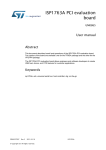
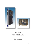
◆ Timing for DMA /VME64 reading up 32 MB:
The following graph displays the access times over the transfer lengths up to 32 MB
for DMA and VME64 reading, where the NI-VXI driver was running on an SMP
16
Assessment of VME-PCI Interfaces with Linux drivers
kernel. On this scale, the problems with the steps are inferior, ending up in a rate of
11.6 MB/s for DMA reading, and 13.7 MB/s for VME64 reading. Remember that 16
MB/s and 21.3 MB/s are the corresponding maximum rates. However, there is
another problem when carrying out tests with large transfer lengths (approx. 8 MB)
over a longer period of time (approx. 30 minutes), since the program may exits
occasionally with “bus error”. So far no explanation could be found for this
behavior, thus more systematic test runs are needed here.
NI VME-PCI8026 with linux-1.6 driver
3.50
"timing.MXI-2.DMA.32MB.read"
"timing.MXI-2.VME64.32MB.read"
3.00
seconds
2.50
2.00
1.50
1.00
0.50
0.00
0
5
10
15
20
25
30
35
MB
3.4.1
Memory Mapping Transfer
◆ Programming for MM writing:
1:
2:
3:
4:
5:
6:
7:
#define SPACE_A32 0x0003
#define ACCESS_ONLY 0x0000
#define ENDIAN_BIG 0x0000
#define ACCESS_LONGWORD 4
#define WINDOW_SIZE 0x200000
MapVXIAddressSize (WINDOW_SIZE);
address_pci =
(UINT32*) MapVXIAddress (SPACE_A32|ACCESS_ONLY|ENDIAN_BIG,
address_vme, 2000L, &window, &ret);
8: for (i=0; i<length; i++)
VXIpoke (address_pci+i, ACCESS_LONGWORD, *(buffer_pci+i));
9: UnMapVXIAddress (window);
◆ VMEbus cycles for MM reading (16 KB):
VMEbus• National Instruments • writing A32D32 with MM
Time
AM
Address
Data
Size
Cycle
MBytes/s
910 ns
09
32 bit
32 bit
LONG
WRI
4.45
National Instruments VME-PCI8026 Kit
17
◆ Programming for MM reading:
1:
2:
3:
4:
5:
6:
7:
#define SPACE_A32 0x0003
#define ACCESS_ONLY 0x0000
#define ENDIAN_BIG 0x0000
#define ACCESS_LONGWORD 4
define WINDOW_SIZE 0x200000
MapVXIAddressSize (WINDOW_SIZE);
address_pci =
(UINT32*) MapVXIAddress (SPACE_A32|ACCESS_ONLY|ENDIAN_BIG,
address_vme, 2000L, &window, &ret);
8: for (i=0; i<length; i++)
VXIpeek (address_pci+i, ACCESS_LONGWORD, buffer_pci+i);
9: UnMapVXIAddress (window);
◆ VMEbus cycles for MM reading (16 KB):
VMEbus • National Instruments • reading A32D32 with MM
Time
AM
Address
Data
Size
Cycle
1.75 µs
09
32 bit
32 bit
LONG
RD
MBytes/s
2.28
◆ Timing for MM reading/writing:
The following graph displays the access times over the transfer lengths for both
MM reading and writing. There exists a linear relation with no setup time for MM
reading with 2.1 MB/s, and for MM writing with 4.2 MB/s. No anomalies could be
observed under this transfer mode. Note that window size can be up to 2 GB,
which need to be set/checked by function MapVXIAddressSize() before the
mapping is established with function MapVXIAddress().
NI VME-PCI8026 with linux-1.6 driver
9.00
"timing.MXI-2.map.read"
"timing.MXI-2.map.write"
8.00
7.00
milliseconds
6.00
5.00
4.00
3.00
2.00
1.00
0.00
0
2
4
6
8
10
KB
12
14
16
18
18
Assessment of VME-PCI Interfaces with Linux drivers
3.5 Concurrent Access
If two concurrent processes running on the PC are accessing the same MXI-2
interface, any combination of transfer modes is working properly. The following
table shows all combinations that have been tested and since each one is working
(label ok), the processes share the interface without problems.
2 processes • National Instruments • concurrent access
access
PIO
read
PIO
write
DMA
read
VME64
read
MM
read
MM
write
PIO
read
ok
ok
ok
ok
ok
ok
ok
ok
ok
ok
ok
ok
ok
ok
ok
ok
ok
ok
ok
ok
PIO
write
DMA
read
VME64
read
MM
read
MM
write
ok
3.6 Multi-hardware Installation
You cannot have multiple PCI-MXI-2 cards in a PC yet, but NI announced that the
new release of NI-VXI driver 3.0 can handle it. However, several VME-MXI-2
extender cards can be daisy-chained by MXI-2 cables, as long as to total length is
below 20 meters. In my setup, only one MXI-2 interface was tested.
SBS Bit 3 Model 617 Adapter
19
4 SBS Bit 3 Model 617 Adapter
4.1 Description
The SBS Bit 3 Model 617 Adapter consists of a single-slot, double-height VMEbus
adapter card and a half-size PCI adapter card. They are connected by a round
EMI-shielded cable with 7.5 meters as maximum length. For a longer length
requirement, consider SBS Bit 3 Model 618 or 620, since they have a fiber cable,
where you can go out to 500 meters. Users get direct access to the VMEbus with
A16/24/32 addressing and D8/16/32 transfer size. Further information about the
hardware and handling of the 617 Adapter can be found in the manual [12]. The
product comes with device drivers for Windows 95/98/NT, AIX, Solaris, etc., but
not for the Linux operating systems. Fortunately, [13] has developed such drivers
for Linux and in my setup the vmehb-2.2.6 driver (initially vmehb-2.2.2) was
used. In the following the installation procedure and the performance results will
be presented.
4.2 Driver Installation
1. Login as root
2. Download and unpack the driver:
# mkdir /usr/local/vmehb-2.2.6
# cd /usr/local/vmehb-2.2.6
download
ftp.nikhef.nl/pub/projects/vmehb/ftp/vmehb-2.2.6.tar.gz into
/usr/local/vmehb-2.2.6
# tar vxfz vmehb-2.2.6.tar.gz
3. Set up devices and man-pages:
# make devices
Check: # ls -l /dev/vme*
# make man
In case of problems: # groff -Tascii -man vmehb.8 > vmehb.man
# make help
4. Compile the kernel module:
# make
5. Load the kernel module:
# insmod vmehb-2.2.6-2.2.12-20.o
Check: # /sbin/lsmod
Check: # tail -50 /var/log/messages
Check: # cat /proc/pci
6. Loading the kernel module at boot time:
place the command insmod vmehb-2.2.6-2.2.12-20.o in file
/etc/rc.d/rc.local
7. Simple tests:
# cd /usr/local/vmehb-2.2.6
# vmetst
20
Assessment of VME-PCI Interfaces with Linux drivers
In version 2.2.6 the Makefile detects if Linux is running in SMP mode or not.
Depending on that, the kernel modules vmehb-2.2.6-2.2.12-20.o or
vmehb-2.2.6-2.2.12-20smp.o were build in my setup. The minimal
SMP_NEWFLAG flag in Makefile I could find out is -DLIN2_2 -w
-DEXPORT_SYMTAB -D__SMP__ -DMODVERSIONS -include
/usr/src/linux/include/linux/modversions-smp.h. Loading the driver
can be sometimes a problem, since the PCI card of the Model 617 adapter cannot
share interrupts, see Chapter 2.2. You must reload the vmehb driver each time the
VME chassis power is cycled, but no reboot is necessary. When memory mapped
transfers took place, unloading the driver fails, since the module count is not
maintained properly. In this case only a reboot helps. A few customizations are
possible to the vmehb driver by modifying the vmehb_conf.h file. For example,
the DMA buffer size can be set by the macro MAX_DMA_SIZE, or the address
modifier (AM) of the various transfer modes by changing the am field of the
vme_config[] structure. Remark that the VMEbus adapter card of the 617 Model
has many jumpers to set (system controller, VMEbus arbitration, interrupts, etc.).
No software tool is available to override these settings.
4.3 Data Transfer
The Model 617 Adapter transfers data in PIO, DMA and memory mapped mode,
but VME64 is not supported. The different transfer modes are achieved by opening
resp. closing a certain UNIX devices with the open() resp. close() system call.
For example device /dev/vme24d32 means A24 addressing and D32 transfer size
in PIO mode. The programming is straightforward with read(), write(),
leek(), and mmap() system calls. Note that all length parameters must be given
in bytes. In the MM mode, the type of the pointer determinates the transfer size, not
the opened device. Also some ioctl() calls are implemented, but they are only
for special use. In the following the programming, the VMEbus cycles and the
timing of the three transfer modes will be presented.
4.3.1
PIO Transfer
◆ Programming for PIO writing:
1:
2:
3:
4:
5:
#define VMEHB_DEV "/dev/vme32d32"
vmehb_fd = open (VMEHB_DEV, O_RDWR);
lseek (vmehb_fd, address_vme, SEEK_SET);
cnt = write (vmehb_fd, buffer_pci, length);
close (vmehb_fd);
◆ VMEbus cycles for PIO writing (16 KB):
VMEbus • SBS Bit 3 • writing A32D32 with PIO
Time
AM
Address
Data
Size
Cycle
MBytes/s
370 ns
0D
32 bit
32 bit
LONG
WRI
10.5
◆ Programming for PIO reading:
SBS Bit 3 Model 617 Adapter
1:
2:
3:
4:
5:
21
#define VMEHB_DEV "/dev/vme32d32"
vmehb_fd = open (VMEHB_DEV, O_RDWR);
lseek (vmehb_fd, address_vme, SEEK_SET);
cnt = read (vmehb_fd, buffer_pci, length);
close (vmehb_fd);
◆ VMEbus cycles for PIO reading (16 KB):
VMEbus • SBS Bit 3 • reading A32D32 with PIO
Time
AM
Address
Data
Size
Cycle
430 ns
0D
32 bit
32 bit
LONG
RD
MBytes/s
8.9
◆ Timing for PIO reading/writing:
The following graph displays the access times over the transfer lengths for both
PIO reading and writing with device /dev/vme24d32. There exists a linear
relation with 150 µs setup time and a rate of 8.5 MB/s for reading, and 10 MB/s for
writing. Using device /dev/vme32d16 instead, only 1.6 MB/s could be achieved.
SBS Bit3 Model 617 with vmehb-2.2.6 driver
2.50
"timing.BIT3.vme32d32.read"
"timing.BIT3.vme32d32.write"
milliseconds
2.00
1.50
1.00
0.50
0.00
0
2
4
6
8
10
12
14
16
18
KB
◆ Access to non-existing VME address:
In an earlier version of the vmehb driver, a read or write access to an unused
VMEbus address (no board in the crate responds) could not be recognized, since
the contents of the internal driver buffer was touched and a BERR occured on the
VMEbus. There is an improvement for version 2.2.6 of the vmehb driver, since a
mismatch between the length parameter for the read() or write() system call
and the return value indicates an access problem. Unfortunately, it does not work
22
Assessment of VME-PCI Interfaces with Linux drivers
for small lengths (approx. 100 bytes) since Linux takes some time to respond to
interrupts. Also watch out /var/log/messages for some error messages. Hence,
access to non-existing VME addresses can not be reliably detected, which makes a
debugging of an application program difficult. This applies to the other transfer
modes as well.
4.3.2
DMA Transfer
◆ Programming for DMA writing:
1:
2:
3:
4:
5:
#define VMEHB_DEV "/dev/vmm32d32"
vmehb_fd = open (VMEHB_DEV, O_RDWR);
lseek (vmehb_fd, address_vme, SEEK_SET);
cnt = write (vmehb_fd, buffer_pci, length);
close (vmehb_fd);
◆ VMEbus cycles for DMA writing (16 KB):
VMEbus Timing • SBS Bit 3 • writing A32D32 with DMA
Time
AM
Address
Data
Size
Cycle
130 ns
0B
32 bit
32 bit
LONG
WBLK
5.45 µs at *256 B
0B
32 bit
32 bit
LONG
WRI
MBytes/s
19.2
◆ Programming for DMA reading:
1:
2:
3:
4:
5:
#define VMEHB_DEV "/dev/vmm32d32"
vmehb_fd = open (VMEHB_DEV, O_RDWR);
lseek (vmehb_fd, address_vme, SEEK_SET);
cnt = read (vmehb_fd, buffer_pci, length);
close (vmehb_fd);
◆ VMEbus cycles for DMA reading (16 KB):
VMEbus Timing • SBS Bit 3 • reading A32D32 with DMA
Time
AM
Address
Data
Size
Cycle
110 ns
0B
32 bit
32 bit
LONG
RBLK
950 ns at *256 B
0B
32 bit
32 bit
LONG
RD
MBytes/s
27.0
◆ Timing for DMA reading/writing:
The following graph displays the access times over the transfer lengths for both
DMA reading and writing with device /dev/vmm32d32. There exists a linear
relation with 150 µs setup time and a rate of 22.5 MB/s for reading, and 16 MB/s
for writing. Using device /dev/vmm32d16 instead, only 2 MB/s could be
achieved.
SBS Bit 3 Model 617 Adapter
23
SBS Bit3 Model 617 with vmehb-2.2.6 driver
1.40
"timing.BIT3.vmm32d32.read"
"timing.BIT3.vmm32d32.write"
1.20
milliseconds
1.00
0.80
0.60
0.40
0.20
0.00
0
2
4
6
8
10
12
14
16
18
KB
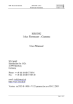
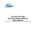
◆ Timing for DMA reading/writing up 32 MB:
The following graph displays the access times over the transfer lengths up to 32 MB
for DMA reading and writing, where the vmehb driver was running on an SMP
kernel. In earlier versions of the vmehb driver, 2 MB was the limit of a DMA
transfer. However, version 2.2.6 of the vmehb driver can handle up to 2 GB by
reusing the DMA buffer. The size of the latter is set by macro MAX_DMA_SIZE in file
vmehb_conf.h, where the default is 0x8000 (32 KB). No problems occured
during this long-term test.
SBS Bit3 Model 617 with vmehb-2.2.6 driver
3.00
"timing.BIT3.vmm32d32.32MB.read"
"timing.BIT3.vmm32d32.32MB.write"
2.50
seconds
2.00
1.50
1.00
0.50
0.00
0
5
10
15
20
MB
25
30
35
24
Assessment of VME-PCI Interfaces with Linux drivers
◆ Non-aligned access for DMA reading:
The following table shows the results when non-aligned accesses are made on the
VMEbus. A non-aligned start address always resulted in a -1 return value of the
read() and write() system calls, and nothing happened on the VMEbus (label
nothing). If the length is non-aligned, additional D32A32 accesses took place, but
data is missing in the reading buffer on the PC. If both the start address and the
length is aligned, no pre-reads could be observed and the data was complete. This
was also verified for a transfer with 300 bytes (0x12C), 400 bytes (0x190), or 500
(0x1F4) bytes.
VMEbus • SBS Bit 3 • non-aligned reading A32D32 with DMA
Length
0x100
0x101
0x102
0x103
0x03C00000
256 bytes read,
data complete
512 bytes read,
3 bytes missing
512 bytes read,
2 bytes missing
512 bytes read,
1 byte missing
0x03C00001
nothing
nothing
nothing
nothing
0x03C00002
nothing
nothing
nothing
nothing
0x03C00003
nothing
nothing
nothing
nothing
Start
4.3.3
Memory Mapping Transfer
◆ Programming for MM writing:
1:
2:
3:
4:
5:
#define VMEHB_DEV "/dev/vmm32d32"
#define WINDOW_SIZE 0x200000
vmehb_fd = open (VMEHB_DEV, O_RDWR);
lseek (vmehb_fd, address_vme, SEEK_SET);
address_pci = mmap (0, WINDOW_SIZE, PROT_READ|PROT_WRITE,
MAP_SHARED, vmehb_fd, address_vme);
6: for (i=0; i<length; i++)
*(address_pci+i) = *(buffer_pci+i);
7: munmap (addr_pci, WINDOW_SIZE);
8: close (vmehb_fd);
◆ VMEbus cycles for MM writing (16 KB):
VMEbus • SBS Bit 3 • writing A32D32 with MM
Time
AM
Address
Data
Size
Cycle
MBytes/s
2.25 µs
0D
32 bit
32 bit
LONG
WRI
1.77
◆ Programming for MM reading:
1:
2:
3:
4:
5:
#define VMEHB_DEV "/dev/vmm32d32"
#define WINDOW_SIZE 0x200000
vmehb_fd = open (VMEHB_DEV, O_RDWR);
lseek (vmehb_fd, address_vme, SEEK_SET);
address_pci = mmap (0, WINDOW_SIZE, PROT_READ|PROT_WRITE,
SBS Bit 3 Model 617 Adapter
25
MAP_SHARED, vmehb_fd, address_vme);
6: for (i=0; i<length; i++)
*(buffer_pci+i) = *(address_pci+i);
7: munmap (addr_pci, WINDOW_SIZE);
8: close (vmehb_fd);
◆ VMEbus cycles for MM reading (16 KB):
VMEbus • SBS Bit 3 • readingA32D32 with MM
Time
AM
Address
Data
Size
Cycle
2.57 µs
0D
32 bit
32 bit
LONG
RD
MBytes/s
1.51
◆ Timing for MM reading/writing:
The following graph displays the access times over the transfer lengths for both
MM reading and writing with device /dev/vme32d32. There exists a linear
relation with no setup time and a rate of 1.5 MB/s for reading, and 1.8 MB/s for
writing. Note that the window size can be up to 32 MB in multiples of the page size
(4 KB), which is established be the mmap() system call. Use MAP_SHARED as flag
parameter.
SBS Bit3 Model 617 with vmehb-2.2.6 driver
12.00
"timing.BIT3.mmap.read"
"timing.BIT3.mmap.write"
10.00
milliseconds
8.00
6.00
4.00
2.00
0.00
0
2
4
6
8
10
12
14
16
18
KB
4.4 Concurrent Access
The following table shows what happens if two concurrent processes running on
the PC try to access the same Bit 3 interface. Device /dev/vme32d32 was used for
PIO and MM transfers, and device /dev/vmm32d32 for DMA transfers. As long as
MM was not involved, all combinations of transfer modes were working properly
26
Assessment of VME-PCI Interfaces with Linux drivers
(label ok), which means that both processes did run concurrently. But combinations
with MM stopped the PC and a reboot was necessary (label hang). Hence do not
use memory mapped accesses when other transfers are going on.
2 processes • SBS Bit 3 • concurrent access
access
PIO
read
PIO
write
DMA
read
DMA
write
MM
read
MM
write
PIO
read
ok
ok
ok
ok
hang
hang
ok
ok
ok
hang
hang
ok
ok
hang
hang
ok
hang
hang
ok
ok
PIO
write
DMA
read
DMA
write
MM
read
MM
write
ok
Opening two or more devices within the same program did work well for all
transfer mode combinations.
4.5 Multi-hardware Installation
The current release of the vmehb driver is not designed to handle multiple PCI
cards in a PC. Also no daisy-chaining is possible.
Summary
27
5 Summary
The following table synopsizes the assessment of the three VME-PCI interfaces.
Wiener
PCIVME Link
features
National Instruments
VME-PCI8026 Kit
SBS Bit 3
Model 617 Adapter
PIO read
1.1 MB/s
8.0 MB/s
8.5 MB/s
DMA read
not implemented
11.5 MB/s
(peak 16.0 MB/s)
22.5 MB/s
VME64 read
not implemented
13.6 MB/s
(peak 21.3 MB/s)
not implemented
MM read
not working
2.1 MB/s
1.5 MB/s
PIO write
0.3 MB/s
8.3 MB/s
10.0 MB/s
DMA write
not implemented
not implemented
16.0 MB/s
not working
4.2 MB/s
1.8 MB/s
MM write
16 KB block size,
tested up to 1 MB
occasional bus error,
tested up to 32 MB
32 KB internal buffer,
tested up to 32 MB
SMP capable
no
yes
yes
concurrent access
no
all combinations
yes, except MM
with PIO or DMA
program exists
can be detected
can be detected, but
not for small lengths
pre-reads
byte/word reads, data
missing/corrupted
pre-reads, data
missing
cannot share interrupt
conflict with Ethernet
network card
cannot share interrupt
only controller,
set by jumpers
controller and slave,
set by detection
controller and slave,
set by jumpers
SCSI-2 cable,
max. 10 m
MXI-2 cable,
max. 20 m
custom cable,
max. 7.5 m
data length
non-existing
VME address
non-aligned access
PCI slot
VME system
controller
cable
miscellaneous
•
spurious
VMEbus resets
•
utilities: resman,
vxitedit, victext
•
tests executed
under root
•
many parameters
•
•
multi-hardware
installation
daisy-chain of
VME-MXI-2
extenders
•
utilities: vmetst
•
driver unloading
problems
•
multi-hardware
installation not
supported
28
Assessment of VME-PCI Interfaces with Linux drivers
References
[1]
[2]
[3]
[4]
[5]
[6]
[7]
[8]
[9]
[10]
[11]
[12]
[13]
Richard J. O’Connor, “Interfacing VMEbus to PCIbus: It’s not as easy as you might
think”, VMEbus Systems Magazine, August 1996, World-Wide Web document:
http://www.vmebus-systems.com/pdf/Tundra.Aug96.pdf
Hewlett-Packard Co., World-Wide Web page: http://www.support.kayak.hp.com
CERN, IT Division, World-Wide Web page:
http://wwwinfo.cern.ch/pdp/ose/linux/linux_CERN.html
W-IE-N-ER Plein&Baus GmbH, “PCI-VME PCI to VME Interface User’s Manual“,
June 1999, World-Wide Web document: http://www.wiener-d.com/Pcivme.pdf
Hermann-Josef Mathes et. al., Forschungszentrum Karlsruhe (FZK), private
communications
PLX Technology Inc., “PLXMon User’s Guide”, January 1997, World-Wide Web
document: http://www.plxtech.com/
National Instruments Co., “NI-VXI Getting Started with Your VXI/VME-PCI8026
and the NI-VXI/NI-VISA Software for Linux“, December 1999, World-Wide Web
document: http://www.ni.com/pdf/manuals/322651a.pdf
National Instruments Co., “NI-VXI Text Utilities Reference Manual”, October
1993, World-Wide Web document: http://www.ni.com/pdf/manuals/320321.pdf
National Instruments Co., “NI-VXI Programmer Reference Manual“, July 1996,
World-Wide Web document: http://www.ni.com/pdf/manuals/321272a.pdf
National Instruments Co., “NI-VXI User Manual“, July 1996, World-Wide Web
document: http://www.ni.com/pdf/manuals/321228a.pdf
Geraldine Thomas, CERN - EP/ESS, “Selection of a PC for the NA45/CERES
experiment“, April 2000
SBS Technologies Inc., “Model 617 Adapter Hardware Manual“, December 1998,
World-Wide Web document: http://www.bit3.com/cp_adapter_d.shtml
Natalia Kruszynska, The National Institute for Nuclear Physics and High Energy
Physics (NIKEF), private communications