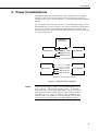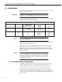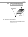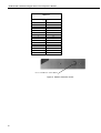
1
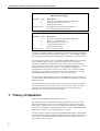
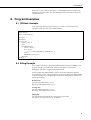
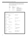
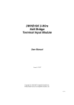
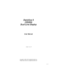
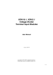
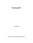
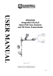
SDM-CD16D 16-Channel
Digital Control Port
Expansion Module
User Manual
Issued 13.11.07
Copyright © 2000-2007 Campbell Scientific Inc.
Printed under licence by Campbell Scientific Ltd.
CSL 404
Guarantee
This equipment is guaranteed against defects in materials and
workmanship. This guarantee applies for twelve months from date of
delivery. We will repair or replace products which prove to be defective
during the guarantee period provided they are returned to us prepaid. The
guarantee will not apply to:
•
Equipment which has been modified or altered in any way without the
written permission of Campbell Scientific
•
Batteries
•
Any product which has been subjected to misuse, neglect, acts of God
or damage in transit.
Campbell Scientific will return guaranteed equipment by surface carrier
prepaid. Campbell Scientific will not reimburse the claimant for costs
incurred in removing and/or reinstalling equipment. This guarantee and the
Company’s obligation thereunder is in lieu of all other guarantees,
expressed or implied, including those of suitability and fitness for a
particular purpose. Campbell Scientific is not liable for consequential
damage.
Please inform us before returning equipment and obtain a Repair
Reference Number whether the repair is under guarantee or not. Please
state the faults as clearly as possible, and if the product is out of the
guarantee period it should be accompanied by a purchase order.
Quotations for repairs can be given on request.
When returning equipment, the Repair Reference Number must be clearly
marked on the outside of the package.
Note that goods sent air freight are subject to Customs clearance fees
which Campbell Scientific will charge to customers. In many cases, these
charges are greater than the cost of the repair.
Campbell Scientific Ltd,
Campbell Park, 80 Hathern Road,
Shepshed, Loughborough, LE12 9GX, UK
Tel: +44 (0) 1509 601141
Fax: +44 (0) 1509 601091
Email: [email protected]
www.campbellsci.co.uk
Contents
PDF viewers note: These page numbers refer to the printed version of this document. Use
the Adobe Acrobat® bookmarks tab for links to specific sections.
1. Introduction.................................................................. 1
2. Control Specifications ................................................ 2
2.1 General......................................................................................................2
2.2 Output Specifications................................................................................2
3. Power Considerations................................................. 3
4. Installation.................................................................... 4
4.1 Controlled Device Connections ................................................................4
5. Address Selection Switches....................................... 5
6. Datalogger Instructions .............................................. 7
6.1 CRBasic ....................................................................................................7
6.2 Edlog.........................................................................................................7
7. Theory of Operation .................................................... 8
8. Program Examples ...................................................... 9
8.1 CRBasic Example .....................................................................................9
8.2 Edlog Example .........................................................................................9
Figures
1.
2.
3.
4.
5.
SDM-CD16D..............................................................................................1
Equivalent Output Driver Circuit ...............................................................2
Connection Block Diagrams.......................................................................3
Use of Terminal Blocks ..............................................................................5
Address Selection Switch ...........................................................................6
Tables
1. Datalogger to SDM-CD16D Connections ..................................................4
2. Switch Position and Addresses...................................................................6
i
This is a blank page.
SDM-CD16D 16 Channel Digital Control
Port Expansion Module
The SDM-CD16D (see Figure 1) is a synchronously addressed peripheral. It has 16 control
ports.
Figure 1. SDM-CD16D
1. Introduction
The SDM-CD16D expands the digital output capability of Campbell Scientific
dataloggers. The outputs can be set to 0 or 5 V by the datalogger. In addition to
being able to drive normal logic level inputs, when an output is set HI a ‘boost’
circuit allows it to source a current of up to 100 mA, allowing direct control of
low voltage valves, relays etc.
The SDM-CD16D is a synchronously addressed datalogger peripheral. Three
ports on the datalogger are used to address the SDM-CD16D then clock out the
desired state of each of the 16 control ports. Up to sixteen SDM-CD16Ds may be
addressed, making it possible to control a maximum of 256 ports from three
datalogger SDM ports.
In CRBasic, instruction SDMCD16AC is used to control the SDM-CD16D. In
Edlog, Instruction 104 is typically used; older CR7 dataloggers use Instruction 29.
NOTE
Older CR7 dataloggers with pre-OS7.1 software may not have the
necessary instruction. Ensure that your datalogger contains the
appropriate instruction before using.
1
SDM-CD16D 16 Channel Digital Control Port Expansion Module
2. Control Specifications
2.1 General
Compatible dataloggers:
CR800, CR850, CR1000, CR3000, CR5000,
CR10(X), CR23X, CR7 and 21X
Operating voltage:
12 VDC nominal (9 to 18 V)
Current drain at 12V DC: 100 µA typical (All ports HI, no load)
Total cable length:
6 m (CR10/10X, CR23X, 21X), 180 m (CR7)
2.2 Output Specifications
Output Voltage (no load): Output ON/HI, Nominal 5 V (Minimum 4.5 V)
Output OFF/LO, Nominal 0 V (Maximum 0.1 V)
NOTE
Output Sink Current:
Output will sink 8.6 mA from a 5 V source*
Output Source Current:
Output will source 36 mA @ 3 V,
115 mA short-circuited to ground*
Max. Output Current:
(total all outputs)
400 mA at 50°C and 12 V supply (see NOTE below)
The maximum current should be derated under the following
conditions: 50 mA for every 10°C above 50°C and/or 50 mA for
every volt above 12 V.
Operating temp.:
-25°C to +70°C standard
Size:
230 mm wide x 100 mm high x 24 mm deep
Weight:
350 g
EMC Status:
Complies with EN55022-1:1998 and
EN50082-1:1998
* If more detailed output characteristics are required, experienced users should
consult the equivalent circuit diagrams shown in Figure 2, below.
0.6V Drop
Output
580R
510R
39R
Output
5V, 0Ω V
Output set ON/HI
Output set OFF/LO
Figure 2. Equivalent Output Driver Circuit
2
User Manual
3. Power Considerations
The SDM-CD16D power requirements are large compared to most Campbell
Scientific products when driving significant loads. For many applications an
external power supply, as shown in Figure 3, is recommended to power the SDMCD16D.
For some applications it may be convenient to use the datalogger supply to power
the SDM-CD16D, as shown in Figure 3. For long-term applications, the lead-acid
power supply available with Campbell Scientific dataloggers should be used,
allowing the batteries to be float charged. Alkaline batteries are not recommended
for long term applications.
EXTERNAL
9 TO 18V DC
+
–
GND
SDM-CD16D
C1
12V 12V
SDM-C1 or C1
SDM-C2 or C2
C2
SDM-C3 or C3
C3
DATALOGGER
Connection with External Supply
GND
SDM-CD16D
12V
SDM-C1 or C1
C1
SDM-C2 or C2
C2
SDM-C3 or C3
C3
DATALOGGER
Connection with Datalogger Supply
Figure 3. Connection Block Diagrams
NOTE
If the 21X power supply is used to power the SDM-CD16D, all low
level analogue measurements (thermocouples, pyranometers,
thermopiles, etc.) must be made differentially. This is a result of
slight ground potentials created along the 21X analogue terminal
strip when the 12 V supply is used to power peripherals. This
limitation reduces the number of available analogue input channels
and may make an external supply for the SDM-CD16D essential.
3
SDM-CD16D 16 Channel Digital Control Port Expansion Module
4. Installation
For correct operation the SDM-CD16D must be installed where there is no risk of
water ingress or condensation.
The order in which connections are made is critical. Always
connect 12 V first, followed by ground, then the control ports.
CAUTION
For datalogger connections, see Table 1, below. Please refer to Figure 4 for details
of how to use the spring-loaded terminals.
Table 1. Datalogger to SDM-CD16D Connections
Connection Order
SDM-CD16D
First
12 V
Second
C1
C2
C3
NOTE
CR800, CR850,
CR1000, CR7,
CR10(X), CR23X, 21X
CR3000,
CR5000
12 V on datalogger or
external supply
12 V on datalogger or
external supply
Power
G
SDM-C1
SDM-C2
SDM-C3
Common Ground
Data
Clock
Enable
or G
C1
C2
C3
Function
On a CR7, SDMs connect to the ports at the upper right corner of
the 700X control module.
Multiple SDM-CD16Ds may be wired in parallel by connecting the datalogger
side of one SDM-CD16D to the next.
The transient protection of the SDM-CD16D relies on a low resistance path to
earth. Ensure that the ground return wire has as low a resistance as possible.
Where long cable runs are likely, or where lightning damage is a possibility, the
SDM-CD16D can be fitted with gas discharge tubes. Please contact Campbell
Scientific for details.
NOTE
For CR7 dataloggers, the total cable length can be up to 180 m. For
our other dataloggers, the total cable length connecting SDMCD16Ds to SDM-CD16Ds and the datalogger should not exceed 6
m. Total cable lengths in excess of 6m will adversely affect
communication performance.
4.1 Controlled Device Connections
The SDM-CD16D uses spring-loaded terminal blocks, which provide quick,
vibration resistant, connections. The output terminals are labelled 1 to 16. A
common ground connector is provided between each pair of terminals.
Use a screwdriver in either the top or front slot, as appropriate, to open the
terminal spring. Strip any insulation from the wire to give 7 to 9 mm bare wire.
Push the wire into the opening, and, while holding it in position, withdraw the
screwdriver to release the spring. The wire will now be firmly held in place. See
Figure 4, below.
4
User Manual
NOTE
You cannot reliably insert more than one solid-core wire into one
terminal connector unless the wires are soldered or clamped
together. When inserting more than one stranded wire, twist the
bare ends together before insertion.
Use a screwdriver in appropriate slot
to release spring tension
Strip insulation
and insert wire
Figure 4. Use of Terminal Blocks
5. Address Selection Switches
Each SDM-CD16D can have 1 of 16 addresses. The factory-set address is 00.
Table 2 shows switch position and the corresponding address. Figures 1 and 5
show the position of the switch. Note that you will have to remove the mounting
bracket to gain access to this switch.
5
SDM-CD16D 16 Channel Digital Control Port Expansion Module
Table 2. Switch Position and
Addresses
Switch Setting
Base 4 Address
0
1
2
3
4
5
6
7
8
9
A
B
C
D
E
F
00
01
02
03
10
11
12
13
20
21
22
23
30
31
32
33
Use a screwdriver to select address
Figure 5. Address Selection Switch
6
User Manual
6. Datalogger Instructions
6.1 CRBasic
The SDMCD16AC instruction in CRBasic is used by our CR800, CR850,
CR1000, CR3000, and CR5000 dataloggers. With this instruction, a port on an
SDM-CD16D is enabled/disabled (turned on or off) by sending a value to it. A
non-zero value will enable the port; a zero value disables it. The values to be sent
to the SDM-CD16D are held in the Source array.
Syntax
SDMCD16AC (Source, Reps, SDMAddress)
Remarks
The SDMCD16AC instruction has the following parameters:
Source
The Source parameter is an array which holds the values that will
be sent to the SDM-CD16D to enable/disable its ports. An SDMCD16D has 16 ports; therefore, the source array must be
dimensioned to 16 times the number of Repetitions (the number
of SDM-CD16D devices to be controlled). As an example, with
the array CDCtrl(32), the value held in CDCtrl(1) will be sent to
port 1, the value held in CDCtrl(2) will be sent to port 2, etc. The
value held in CDCtrl(32) would be sent to port 16 on the second
SDM-CD16D.
Reps
The Reps parameter is the number of SDM-CD16D devices that
will be controlled with this instruction.
SDMAddress
The SDMAddress parameter is used to define the address of the
SDM-CD16D that will be controlled with this instruction. Valid
SDM addresses are 0 through 14. Address 15 is reserved for the
SDMTrigger instruction. If the Reps parameter is greater than 1,
the datalogger will increment the SDM address for each
subsequent device that it communicates with.
6.2 Edlog
Instruction 104 is used by the CR10/10X, CR23X, CR7 and 21X to control the
SDM-CD16D, and Instruction 29 is used by older CR7s. The Instruction
descriptions are shown below.
7
SDM-CD16D 16 Channel Digital Control Port Expansion Module
Instruction 104 – SDM-CD16D used with CR10/10X, CR23X,
CR7and 21X dataloggers
Parameter
1
2
3
Type
2
2
4
Execution Time =
Description
Reps (No. of modules sequentially addressed)
Starting Address (base 4: 00..33)
Starting Input Location
2 ms per Rep for the CR10/10X and CR23X
3.5 ms per Rep for the 21X and CR7
Instruction 29 – SDM-CD16D used with older CR7s
Parameter
1
2
3
4
5
Type
2
2
2
2
4
Execution Time =
Description
Reps (No. of modules sequentially addressed)
Device (2 = SDM-CD16D)
Starting Address (base 4: 00..33)
Card (Excitation card No.)
Starting Input Location
150 ms to 190 ms per Rep
The number of SDM-CD16Ds to be addressed is defined by the Reps (repetitions)
parameter. Each Rep sequentially addresses (00, 01, 02,...32, 33) SDM-CD16Ds,
starting with the address specified in parameter 2 (parameter 3 for Instruction 29).
For each repetition, the 16 ports of the addressed SDM-CD16D are set according
to 16 sequential input locations starting at the input location specified in
parameter 3 (parameter 5 for Instruction 29). Any non-zero value stored in an
input location activates (sets HI 5 V) the associated SDM-CD16D port. A value of
zero (0) de-activates the port (sets LO 0 V). For example, assuming two
repetitions and a starting input location of 33, outputs 1 to 16 of the first SDMCD16D are set according to input locations 33 to 48, and outputs 1 to 16 of the
second SDM-CD16D are set according to input locations 49 to 64.
For older CR7s with Instruction 29, the Device (parameter 2) specifies what type
of synchronously addressed peripheral is to be addressed. The Device code for an
SDM-CD16D is 2.
For Instruction 29 only (older CR7s), the Card parameter (parameter 4) specifies
which 725 Excitation Card is being used for the control port signals. The Reps
parameter does not advance beyond the specified Card, requiring another
Instruction 29 for each 725 Excitation Card used.
7. Theory of Operation
On power-up, all SDM-CD16D outputs are off /LO.
The SDM-CD16D is a synchronously addressed peripheral. C2 and C3, driven
high by the datalogger, initiate a cycle. While holding C3 high, the datalogger
drives C2 as a clock line and C1 as a serial data line. The datalogger shifts out a
data bit on C1 (LSB first) on the falling edge of the C2 clock. The SDM-CD16D
shifts in the C1 data bit on the rising edge of the C2 clock.
The first eight bits clocked out represent the SDM-CD16D address. If the address
matches the SDM-CD16D’s address, the SDM-CD16D is enabled. If enabled, the
next 16 bits are shifted into the SDM-CD16D, each bit controlling one port, the
first of which controls output 1.
8
User Manual
When the 16 control bits are clocked in, C2 is held high while C3 is pulsed low
then high to latch the control bits. The datalogger then lowers both C3 and C2 to
complete the cycle.
8. Program Examples
8.1 CRBasic Example
In the following CR1000 program example, a counter is used to fill an array
called Src( ) that will control two SDM-CD16Ds.
'Dimension Variables
Public src(32)
Dim i, count, mask(16)
'Program
BeginProg
for i=1 to 16
mask(i) = 2^(i-1)
next i
Scan(20,msec,2,0)
count = count + 1
for i=1 to 32
src(i) = count AND mask(((i-1) MOD 16) +1)
next i
SDMCD16AC(src(),2,1)
NextScan
EndProg
8.2 Edlog Example
The example is written for the CR10(X) Measurement and Control Module. The
program concepts presented are the same for the CR23X, 21X and CR7
dataloggers with minor changes in the program code.
In this example, the SDM-CD16D is used to control the temperature between
23°C and 28°C in each of five greenhouses. In each greenhouse the SDM-CD16D
controls a heating unit, a refrigerating unit and an air mixing fan according to the
following conditions:
Heating unit:
Activate when temperature <23.5°C.
Deactivate when temperature >25.5°C.
Cooling unit:
Activate when temperature >27.5°C.
Deactivate when temperature <24.5°C.
Mixing fan:
Activate whenever the heating or cooling units are activated.
Activate for 5 minutes out of every 15 minutes.
9
SDM-CD16D 16 Channel Digital Control Port Expansion Module
The program assumes that the temperature measurements have been made, and
that the average temperature for each greenhouse is computed and stored in input
locations 1 to 5. For further information on loops and input location indexing,
please refer to your datalogger manual.
Input location assignments are as follows:
Input
Location
1..5
10..14
Input
Location Label
Temp #1..#5
Heat #1..#5
15..19
Cool #1..#5
20..24
Fan #1..#5
Description
Avg. temp. greenhouse 1..5
Heater control, greenhouse 1..5
SDM-CD16D Port 1..5
Cooler control, greenhouse 1..5
SDM-CD16D Port 6..10
Fan control, greenhouse 1..5
SDM-CD16D Port 11..15
;{CR10X}
;
*Table 1 Program
01: 5
Execution Interval (seconds)
1: Beginning of Loop (P87)
1: 0
Delay
2: 5
Loop Count
Master loop: end
loop at step 30
Start heater control logic
2: If (X<=>F) (P89)
1: 1
-- X Loc [ Temp_1 ]
2: 4
<
3: 23.5
F
4: 30
Then Do
if temperature is below
heater threshold
3: Z=F (P30)
1: 1
2: 0
3: 10
put a ‘1’ into heater control
location
4: End (P95)
end ‘then do’
5: If (X<=>F) (P89)
1: 10
-- X Loc [ Heat_1 ]
2: 2
<>
3: 0
F
4: 30
Then Do
if the heater is on (heater
control location <>0)
6: If (X<=>F) (P89)
1: 1
-- X Loc [ Temp_1 ]
2: 3
>=
3: 25.5
F
4: 30
Then Do
check upper threshold
to see if heater should
be turned off
7: Z=F (P30)
1: 0
2: 0
3: 10
if heater should be turned
off, enter a ‘0’ into
heater control location
8: End (P95)
10
F
Exponent of 10
-- Z Loc [ Heat_1 ]
then
F
Exponent of 10
-- Z Loc [ Heat_1 ]
then
end ‘then do’
User Manual
9: Else (P94)
10: Z=F (P30)
1: 0
2: 0
3: 10
else, if the heater is off
F
Exponent of 10
-- Z Loc [ Heat_1 ]
11: End (P95)
enter a ‘0’ into heater
control location
end ‘then do/else’
End heater control logic
Start cooler control logic
12: If (X<=>F) (P89)
1: 1
-- X Loc [ Temp_1 ]
2: 3
>=
3: 27.5
F
4: 30
Then Do
if ‘cooler on’ threshold
is exceeded
13: Z=F (P30)
1: 1
2: 0
3: 15
put a ‘1’ into cooler
control location
F
Exponent of 10
-- Z Loc [ Cool_1 ]
then
14: End (P95)
end ‘then do’
15: If (X<=>F) (P89)
1: 15
-- X Loc [ Cool_1 ]
2: 2
<>
3: 0
F
4: 30
Then Do
if cooler is on (cooler
control location <>0)
16: If (X<=>F) (P89)
1: 1
-- X Loc [ Temp_1 ]
2: 4
<
3: 24.5
F
4: 30
Then Do
check lower threshold to
see if cooler should be
turned off
17: Z=F (P30)
1: 0
2: 0
3: 15
if cooler should be turned off
put a ‘0’ into cooler control
location
F
Exponent of 1
-- Z Loc [ Cool_1 ]
then
18: End (P95)
end ‘then do’
19: Else (P94)
else, if cooler is off
20: Z=F (P30)
1: 0
2: 0
3: 15
F
Exponent of 10
-- Z Loc [ Cool_1 ]
21: End (P95)
put a ‘0’ into cooler
control location
end ‘then do/else’
End cooler control logic
Start fan control logic based on heater/cooler
11
SDM-CD16D 16 Channel Digital Control Port Expansion Module
22: If (X<=>F) (P89)
1: 10
-- X Loc [ Heat_1 ]
2: 2
<>
3: 0
F
4: 11
Set Flag 1 High
if heater is on
23: If (X<=>F) (P89)
1: 15
-- X Loc [ Cool_1 ]
2: 2
<>
3: 0
F
4: 11
Set Flag 1 High
if cooler is on
24: If Flag/Port (P91)
1: 11
Do if Flag 1 is High
2: 30
Then Do
if flag 1 is set
25: Z=F (P30)
1: 1
2: 0
3: 20
put a ‘1’ into fan control
location
F
Exponent of 10
-- Z Loc [ Fan_1 ]
26: Else (P94)
27: Z=F (P30)
1: 0
2: 0
3: 20
set flag 1
then
else, if flag 1 is reset
F
Exponent of 10
-- Z Loc [ Fan_1 ]
28: End (P95)
29: Do (P86)
1: 21
set flag 1
put a ‘0’ into fan control
location
end ‘then do/else’
reset flag 1
Set Flag 1 Low
30: End (P95)
end master loop
End fan control logic based on heater/cooler
Start fan control logic based on time
31: If time is (P92)
1: 10
Minutes (Seconds --) into a
2: 15
Interval (same units as above)
3: 12
Set Flag 2 High
if 5 minutes remain
out of 15 minute
interval
set flag 2
32: If Flag/Port (P91)
1: 12
Do if Flag 2 is High
2: 30
Then Do
if flag 2 is set
33: Beginning of Loop (P87)
1: 0
Delay
2: 5
Loop Count
start fan loop
34: Z=F (P30)
1: 1
2: 0
3: 20
put a ‘1’ into fan control
location
35: End (P95)
12
F
Exponent of 10
-- Z Loc [ Fan_1 ]
then
end fan loop
User Manual
36: End (P95)
end’ then do’
37: If time is (P92)
1: 0
Minutes (Seconds --) into a
2: 15
Interval (same units as above)
3: 22
Set Flag 2 Low
reset flag 2 at the
end of the 15 minutes
End fan control logic based on time
Input locations 10 to 24 are now loaded with a ‘1’ or ‘0’ to set ports on the SDM-CD16D
38: SDM-CD16 / SDM-CD16D (P104)
1: 1
Reps
2: 00
Address
3: 10
Loc [ Heat_1 ]
send instructions to the
SDM-CD16D with address 00
*Table 2 Program
02: 0.0000
Execution Interval (seconds)
*Table 3 Subroutines
End Program
-Input Locations-1
Temp_1 7 4 0
2 Temp_2 10 0 0
3 Temp_3 10 0 0
4 Temp_4 10 0 0
5 Temp_5 18 0 0
6 _________ 0 0 0
7 _________ 0 0 0
8 _________ 0 0 0
9 _________ 0 0 0
10 Heat_1 7 3 3
11 Heat_2 11 1 0
12 Heat_3 11 1 0
13 Heat_4 11 1 0
14 Heat_5 19 1 0
15 Cool_1 7 3 3
16 Cool_2 11 1 0
17 Cool_3 11 1 0
18 Cool_4 11 1 0
19 Cool_5 19 1 0
20 Fan_1 7 1 3
21 Fan_2 11 1 0
22 Fan_3 11 1 0
23 Fan_4 11 1 0
24 Fan_5 19 1 0
25 _________ 1 1 0
26 _________ 0 0 0
27 _________ 0 0 0
28 _________ 0 0 0
29 _________ 0 0 0
13
CAMPBELL SCIENTIFIC COMPANIES
Campbell Scientific, Inc. (CSI)
815 West 1800 North
Logan, Utah 84321
UNITED STATES
www.campbellsci.com
[email protected]
Campbell Scientific Africa Pty. Ltd. (CSAf)
PO Box 2450
Somerset West 7129
SOUTH AFRICA
www.csafrica.co.za
[email protected]
Campbell Scientific Australia Pty. Ltd. (CSA)
PO Box 444
Thuringowa Central
QLD 4812 AUSTRALIA
www.campbellsci.com.au
[email protected]
Campbell Scientific do Brazil Ltda. (CSB)
Rua Luisa Crapsi Orsi, 15 Butantã
CEP: 005543-000 São Paulo SP BRAZIL
www.campbellsci.com.br
[email protected]
Campbell Scientific Canada Corp. (CSC)
11564 - 149th Street NW
Edmonton, Alberta T5M 1W7
CANADA
www.campbellsci.ca
[email protected]
Campbell Scientific Ltd. (CSL)
Campbell Park
80 Hathern Road
Shepshed, Loughborough LE12 9GX
UNITED KINGDOM
www.campbellsci.co.uk
[email protected]
Campbell Scientific Ltd. (France)
Miniparc du Verger - Bat. H
1, rue de Terre Neuve - Les Ulis
91967 COURTABOEUF CEDEX
FRANCE
www.campbellsci.fr
[email protected]
Campbell Scientific Spain, S. L.
Psg. Font 14, local 8
08013 Barcelona
SPAIN
www.campbellsci.es
[email protected]
Campbell Scientific Ltd. (Germany)
Fahrenheitstrasse13, D-28359 Bremen
GERMANY
www.campbellsci.de
[email protected]
Please visit www.campbellsci.com to obtain contact information for your local US or International representative.