1
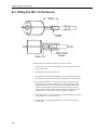
A100R
Switching
Anemometer
User Manual
Issued 16.3.10
Copyright © 2010 Campbell Scientific Ltd
CSL 15
Guarantee
This equipment is guaranteed against defects in materials and
workmanship. This guarantee applies for twelve months from date of
delivery. We will repair or replace products which prove to be defective
during the guarantee period provided they are returned to us prepaid. The
guarantee will not apply to:
•
Equipment which has been modified or altered in any way without the
written permission of Campbell Scientific
•
Batteries
•
Any product which has been subjected to misuse, neglect, acts of God
or damage in transit.
Campbell Scientific will return guaranteed equipment by surface carrier
prepaid. Campbell Scientific will not reimburse the claimant for costs
incurred in removing and/or reinstalling equipment. This guarantee and the
Company’s obligation thereunder is in lieu of all other guarantees,
expressed or implied, including those of suitability and fitness for a
particular purpose. Campbell Scientific is not liable for consequential
damage.
Please inform us before returning equipment and obtain a Repair
Reference Number whether the repair is under guarantee or not. Please
state the faults as clearly as possible, and if the product is out of the
guarantee period it should be accompanied by a purchase order.
Quotations for repairs can be given on request.
When returning equipment, the Repair Reference Number must be clearly
marked on the outside of the package.
Note that goods sent air freight are subject to Customs clearance fees
which Campbell Scientific will charge to customers. In many cases, these
charges are greater than the cost of the repair.
Campbell Scientific Ltd,
Campbell Park, 80 Hathern Road,
Shepshed, Loughborough, LE12 9GX, UK
Tel: +44 (0) 1509 601141
Fax: +44 (0) 1509 601091
Email: [email protected]
www.campbellsci.co.uk
PLEASE READ FIRST
About this manual
Please note that this manual was originally produced by Campbell Scientific Inc. primarily for the
North American market. Some spellings, weights and measures may reflect this origin.
Some useful conversion factors:
Area:
Length:
1 in2 (square inch) = 645 mm2
1 in. (inch) = 25.4 mm
1 ft (foot) = 304.8 mm
1 yard = 0.914 m
1 mile = 1.609 km
Mass:
1 oz. (ounce) = 28.35 g
1 lb (pound weight) = 0.454 kg
Pressure:
1 psi (lb/in2) = 68.95 mb
Volume:
1 UK pint = 568.3 ml
1 UK gallon = 4.546 litres
1 US gallon = 3.785 litres
In addition, while most of the information in the manual is correct for all countries, certain information
is specific to the North American market and so may not be applicable to European users.
Differences include the U.S standard external power supply details where some information (for
example the AC transformer input voltage) will not be applicable for British/European use. Please
note, however, that when a power supply adapter is ordered it will be suitable for use in your country.
Reference to some radio transmitters, digital cell phones and aerials may also not be applicable
according to your locality.
Some brackets, shields and enclosure options, including wiring, are not sold as standard items in the
European market; in some cases alternatives are offered. Details of the alternatives will be covered in
separate manuals.
Recycling information
At the end of this product’s life it should not be put in commercial or domestic refuse
but sent for recycling. Any batteries contained within the product or used during the
products life should be removed from the product and also be sent to an appropriate
recycling facility.
Campbell Scientific Ltd can advise on the recycling of the equipment and in some cases
arrange collection and the correct disposal of it, although charges may apply for some
items or territories.
For further advice or support, please contact Campbell Scientific Ltd, or your local agent.
Campbell Scientific Ltd, Campbell Park, 80 Hathern Road, Shepshed, Loughborough, LE12 9GX, UK
Tel: +44 (0) 1509 601141 Fax: +44 (0) 1509 601091
Email: [email protected]
www.campbellsci.co.uk
Contents
PDF viewers note: These page numbers refer to the printed version of this document. Use
the Adobe Acrobat® bookmarks tab for links to specific sections.
1. Specifications .............................................................. 1
2. Mounting....................................................................... 2
3. Connection to Datalogger ........................................... 2
4. Programming the Datalogger ..................................... 3
4.1 Example Program for CRBasic data loggers ............................................ 3
4.2 Example Program for Edlog data loggers ................................................. 4
5. Replacement of Bearings ............................................ 5
Appendix
A. Fitting and Using the HE-1 De-icing Heater .......... A-1
Figures
1. A100R Anemometer – Sectional View ...................................................... 6
Tables
Instruction 3 Multipliers for Different Execution Intervals with
Option 12 ...................................................................................................... 4
i
A100R Switching Anemometer
The A100R anemometer is a precision instrument which is easily interfaced with Campbell
Scientific dataloggers to give accurate measurements of wind run or mean wind speed. A
magnet turns with the rotor spindle producing a varying field which causes a mercury-wetted
reed switch to make and break contact once per revolution of the rotor. The contacts are
bounce free, and no power is required apart from that necessary to detect contact closure; the
A100R is thus well suited for use on remote sites. The rotor is tested by comparison with a
rotor calibrated at the National Physical Laboratory, and a calibration figure is provided
with each instrument.
The anemometer is constructed from anodised aluminium alloy, stainless steels and weather
resisting plastics. A stainless steel shaft runs in two precision, corrosion-resistant ball-races.
The bearings are protected from the entry of moisture droplets and dust, resulting in an
instrument suitable for permanent exposure to the weather.
In the marine version (A100R3, available to special order) a touching shaft-seal is fitted for
extra protection in place of the standard non-contact seal; please note that this gives a small
increase in the threshold speed.
An optional anti-icing heater can be fitted if required (see Appendix A).
1. Specifications
Threshold Speed:
0.25ms-1 (0.6ms-1 A100R3)
Max. speed:
Accuracy:
Distance Constant:
Calibration:
Temp. Range:
Size:
Rotor:
Weight:
Fixing:
Greater than 75ms-1
l% ±0.1ms-1
5m
0.80 revolutions per metre (1 pulse per 1.25 metres)*
-30°C to +55°C
Height 200mm, case diameter 55mm, attached cable 3m
Standard 150mm diameter 3-cup rotor
350g including standard cable
Rotor: Patented gravity sensitive fastener for rapid
attachment and release.
Anemometer: Standard tripod screw (1/4" BSW/UNC),
taper adapter also available. Note that mounting must be
within 15° of vertical.
Switching Voltage: 100V DC max.
Switching Current: 0.5A max.
Switch Rating: 28W max. (DC resistive)
Duty Cycle: 50% ±5% up to 50ms-1
±10% up to 75ms-1
Contact Resistance: 0.05Ω
Actuating Time: l.5ms
Switch Bounce: NIL
Min. Current: NIL (life not reduced by use in dry circuits)
Switch Life: Rated 25 x 109 operations minimum
Electrical:
* See the individual rotor calibration sheet (and when a
heater is fitted Appendix A) for minor corrections to the
nominal figure.
1
A100R Switching Anemometer
2. Mounting
1.
To attach the rotor, remove the white protector tube, hold the anemometer
slightly out of vertical and lightly push on the rotor until positive location is
obtained. Take care not to damage the cups.
(To remove the rotor, first turn the instrument upside down and press
upwards to release a gravity sensitive catch within the hub which will then
slide off.)
CAUTION
Avoid excessive force, and take care not to damage the cups.
NOTE
The A100R rotor is not interchangeable with the rotor from any
other model of Vector Instruments anemometer.
NOTE
2.
Mount the anemometer using a 1/4" BSW screw into the base. A 6° taper
mounting is available as an alternative for portable applications.
3.
Mount the instrument vertically to ensure accurate results and a long
operational life. Do not operate when the instrument is inclined at more than
15° from the vertical. Bearing wear increases significantly if the anemometer
is not properly levelled
This instrument contains a magnetic reed switch, partly filled with
mercury. If subject to shock or vibration during transit, the mercury
tends to become distributed in globules which may prevent correct
operation of the instrument.
To rectify, hold the anemometer approximately vertical and shake
downwards firmly and sharply. This will drive the mercury back
into its reservoir and force the globules together.
3. Connection to Datalogger
Contact closure is between the yellow and green wires; the blue and red wires are
not used.
Connect the green wire to one of the pulse counting channels on your datalogger
and connect the yellow wire to power ground (see note below). It is also advisable
to connect the screen to ground at the datalogger.
2
User Manual
NOTE
Power ground is marked ‘G’ on the CR200, CR800, CR850,
CR1000, CR3000, CR5000, CR23X, CR10/10X and CR510, and
on the 21X and CR7 dataloggers.
4. Programming the Datalogger
Anemometers of the switching (or ‘contact closure’) type such as the A100R are
measured with the Pulse Count instruction configured for Switch Closure. Output
is required as a wind speed in units of ms-1. The nominal calibration of the A100R
is such that 1ms-1 corresponds to 0.8 pulses/sec*; if the likely maximum wind
speed is 10ms-1, then the maximum pulse rate from the anemometer will be 8.0
pulses/sec.
4.1 Example Program for CRBasic data loggers
`CR1000
`Example program showing measurement of a single A100R sensor
every 2 seconds.
`Declare Variables and Units
Public BattV
Public WS_ms
Units BattV=Volts
Units WS_ms=metres/second
`Define Data Tables
DataTable(Table2,True,-1)
DataInterval(0,1440,Min,10)
Minimum(1,BattV,FP2,False,False)
EndTable
`Main Program
BeginProg
Scan(2,Sec,1,0)
`Default(Datalogger Battery Voltage measurement BattV
Battery)BattV)
`A100R Wind Speed Sensor (CSL) measurement WS_ms
PulseCount(WS_ms,1,1,2,1,1.25,0) `Offset – see
Note below
If WS_ms<0.01 Then WS_ms=0
`Call Data Tables and Store Data
CallTable(Table2)
NextScan
EndProg
3
A100R Switching Anemometer
4.2 Example Program for Edlog data loggers
The most convenient configuration code to use with Instruction 3 is 22 (switch
closure, discard counts from excessive intervals, output frequency).
A typical program would then be:
1:
1:
2:
3:
4:
5:
6:
Pulse (P3)
1
Reps
1
Pulse Channel 1
22
Switch Closure, Output Hz
1
Loc [ Wind_Spd ]
;Input Label
1.25
Mult
0.0
Offset
;Offset – see Note
below
* See the individual rotor calibration sheet (and when a heater is fitted Appendix
A) for minor corrections to the nominal figure.
Older Edlog dataloggers which do not have the frequency output option must be
programmed with configuration code 12. In this case, the multiplier, chosen to
give an output in units of ms-1, depends on the execution interval set for
whichever Table contains the Pulse Count instruction (see Table 1).
Table 1 Instruction 3 Multipliers for Different Execution Intervals with
Option 12
Execution Interval
60s
30s
20s
10s
Multiplier
for A100R Anemometer
0.0208
0.0417
0.0625
0.1250
Example Program
(Execution Interval 20 seconds)
2:
1:
2:
3:
4:
5:
6:
Pulse (P3)
1
Reps
1
Pulse Channel 1
12
Switch Closure, Counts (Discard Bad Intervals)
1
Loc [ Wind_Spd ]
;Input Label
0.0625 Mult
0.0
Offset
;Offset – see Note below
NOTE ON OFFSETS
For general use it is recommended that you use a zero offset with
the A100R anemometer.
Use of a non-zero offset improves low speed accuracy (but adds an
error at higher wind speeds). However, if you need to study very
low wind speeds, and you consider that a non-zero offset may
improve your measurements, you may wish to specify an offset of
0.25 (which represents the instrument’s threshold speed of 0.25ms1).
4
User Manual
5. Replacement of Bearings
The manufacturer recommends that the bearings be changed every 2-3 years. In
dusty environments this interval may need to be reduced.
The procedure is outlined below – the numbers in brackets refer to Figure 1.
1.
Switch off the power, disconnect the cable and remove the instrument from
its mount. Remove the rotor as described earlier. Replace the spindle
protector tube.
2.
Clean the anemometer and rotor using a damp cloth or soapy water (do not
immerse).
3.
Unscrew the nuts holding the base plate (l5) using a 5BA (5.5mm AF) nutdriver. Pull off the base plate, body tube, and circuit module (l6).
4.
Remove the protector tube. Grip the spindle end using a hand-vice with soft
jaws and unscrew the magnetic rotor retaining nut (l0) using a 6BA (5mm
AF) spanner.
5.
Remove the nut, washer and magnetic rotor (9). Unscrew the bearing
retainer screws (8), and pull out the spindle with bearing retainer from
below.
6.
Remove the old seal (2) using a small screwdriver and push out the old top
bearing from below using the spindle. Clean all parts.
7.
Place the lower bearing (6) onto the spindle (4) by inserting the spindle-end
into the packet of bearings (to avoid contamination). Place the bearing
retainer (7) over the bearing and assemble with the top plate. Replace screws
(8).
8.
Slide on the magnetic rotor (9), place the washer (11) over the special nut
(10) and screw on loosely.
9.
Slide on the top bearing (3) by pushing the spindle end into the packet. Press
down using either a special jig, the old (clean) bearing or a small screwdriver
(do not apply excessive pressure to the inner ring). Ease in the new rubber
seal (2).
10. Re-tighten nut (10). Lock this nut and screws (8) with a drop of shellac.
11. Replace the bottom ‘0’ ring and top ‘0’ ring fully up against the flange on
the top plate. Push on the body tube, insert the module (l6) with wires
attached, positioned such that the wires on the base plate will fall into the
space provided at the bottom of the module. If the module is to be changed, a
matching magnetic rotor should be obtained. Alternatively, the small magnet
between the terminals can be broken free, re-adjusted and fixed using epoxy
resin glue. Test for 50% mark/space ratio by connecting the anemometer to
an ohm meter and rotating the spindle. The meter should read half-way
across the scale. Re-wire the green and yellow leads to the outer (lower) two
pins.
12. Ensure that the ‘0’ ring is in place on the base plate (rotate slightly when
applying so that it rolls into place). Replace the base plate.
5
A100R Switching Anemometer
13. Apply non-drying silicone rubber compound around the studs, replace the
washers and nuts (15). Wipe off excess compound.
Figure 1 A100R Anemometer – Sectional View
6
Appendix A. Fitting and Using the HE-1
De-icing Heater
This Appendix gives the specification and details of the optional HE-1 anti-icing heater.
When specified at the time of ordering, the heater is fitted to the sensor during manufacture.
The information below gives full details of fitting the heater to an existing wind sensor.
A.1 Introduction
The heating element must be supplied with a separate external 12V (AC or DC)
power supply.
The effectiveness of the heater is dependent on the prevailing wind speed.
Typically it will provide protection down to -10°C at wind speeds of up to 10m/s
in dry air. The heater does not prevent snow and ice build up on the rotor/vane.
NOTE
When a heater is fitted, the airflow around the sensor is altered
due to the physical shape of the heater, and so the rotor calibration
is affected. Reduce the rotor calibration figure by 1.3% when a
heater is fitted.
A.2 Specifications
Operating Voltage (AC or DC ±5%):
12V
Nominal Current:
Element Resistance (±5%)
Nominal Power Rating:
Temperature Rise*:
0.5A
24 ohms
6W
5.2° [1.7] °C /W
Max. Allowable Temperature**:
70°C
* In still air; figure in square brackets refers to 10m/s wind speed (i.e. anti-icing
of bearings effective to -10°C)
** i.e. should not be operated continuously at ambient temperatures above 39°C
When supplied separately, the HE-1 is equipped with 3 metres of 6mm diameter,
2-wire cable to DEF61-12 part 5 – 0.2mm tinned copper stranded cores; nominal
resistance 40mohms/m; overall braided screen and black pvc sheath. If
extending the cable, use as low a resistance cable as is practical to avoid
reducing the voltage supplied to the heater.
NOTE
The screen is isolated from the heater end of the cable. It should
be earthed at the power supply end to give some protection in the
event of lightning, and also to minimise any interference from
noise on the power supply output.
A-1
A100R Switching Anemometer
A.3 Fitting the HE-1 to the Sensor
Referring to the above illustration, fit the HE-1 heater as follows:
1. Connect the two blue wires together and then connect the supply across the
blue and white wires.
2. Thoroughly clean the surface of the tube.
3. Peel back the protective paper and apply the centre of the heater against the
tube, and work outwards from the centre in both directions around the tube.
4. Place the heat-shrink sleeve over the element as shown. Using a heat gun
(hot air blower), rotate the instrument slowly while applying heat evenly
along the length of the sleeve so that the sleeve just shrinks sufficiently to
touch the tube and element. While still rotating the instrument, move the
heat gun closer in order to shrink the sleeve tightly. Start from the spindle
end and work towards the base in order to exclude any trapped air.
5. Check that the sleeve is in all-round contact with the extension tube, and that
molten adhesive can be seen at the ends.
6. Bend the leads neatly around the instrument, and tie or tape to the cable
from the base.
A-2
Appendix A. Fitting and Using the HE-1 De-icing Heater
A.4 Power Supply Connections
The power consumed by the HE-1 is much greater than the normal requirements
of a standard weather station - e.g 1A at 12V for a wind sensor pair. It is not
advisable to try to draw this power from the normal weather station supply (e.g.
from the PS100E-LA power supply). An alternative 12V power source is
recommended which would normally be provided from an AC mains supply.
A-3
CAMPBELL SCIENTIFIC COMPANIES
Campbell Scientific, Inc. (CSI)
815 West 1800 North
Logan, Utah 84321
UNITED STATES
www.campbellsci.com • [email protected]
Campbell Scientific Africa Pty. Ltd. (CSAf)
PO Box 2450
Somerset West 7129
SOUTH AFRICA
www.csafrica.co.za • [email protected]
Campbell Scientific Australia Pty. Ltd. (CSA)
PO Box 444
Thuringowa Central
QLD 4812 AUSTRALIA
www.campbellsci.com.au • [email protected]
Campbell Scientific do Brazil Ltda. (CSB)
Rua Luisa Crapsi Orsi, 15 Butantã
CEP: 005543-000 São Paulo SP BRAZIL
www.campbellsci.com.br • [email protected]
Campbell Scientific Canada Corp. (CSC)
11564 - 149th Street NW
Edmonton, Alberta T5M 1W7
CANADA
www.campbellsci.ca • [email protected]
Campbell Scientific Centro Caribe S.A. (CSCC)
300N Cementerio, Edificio Breller
Santo Domingo, Heredia 40305
COSTA RICA
www.campbellsci.cc • [email protected]
Campbell Scientific Ltd. (CSL)
Campbell Park
80 Hathern Road
Shepshed, Loughborough LE12 9GX
UNITED KINGDOM
www.campbellsci.co.uk • [email protected]
Campbell Scientific Ltd. (France)
Miniparc du Verger - Bat. H
1, rue de Terre Neuve - Les Ulis
91967 COURTABOEUF CEDEX
FRANCE
www.campbellsci.fr • [email protected]
Campbell Scientific Spain, S. L.
Psg. Font 14, local 8
08013 Barcelona
SPAIN
www.campbellsci.es • [email protected]
Campbell Scientific Ltd. (Germany)
Fahrenheitstrasse13, D-28359 Bremen
GERMANY
www.campbellsci.de • [email protected]
Please visit www.campbellsci.com to obtain contact information for your local US or International representative.