1
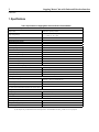
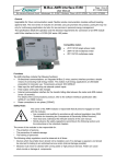
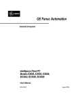
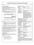
GE Fanuc Automation
Programmable Control Products
Stepping Motor Cube™
with Pulse and Direction Interface
User’s Manual
GFK-2209
July 2002
GFL-002
Warnings, Cautions, and Notes
as Used in this Publication
Warning
Warning notices are used in this publication to emphasize that hazardous voltages,
currents, temperatures, or other conditions that could cause personal injury exist in this
equipment or may be associated with its use.
In situations where inattention could cause either personal injury or damage to
equipment, a Warning notice is used.
Caution
Caution notices are used where equipment might be damaged if care is not taken.
Note
Notes merely call attention to information that is especially significant to understanding and
operating the equipment.
This document is based on information available at the time of its publication. While efforts
have been made to be accurate, the information contained herein does not purport to cover all
details or variations in hardware or software, nor to provide for every possible contingency in
connection with installation, operation, or maintenance. Features may be described herein
which are not present in all hardware and software systems. GE Fanuc Automation assumes no
obligation of notice to holders of this document with respect to changes subsequently made.
GE Fanuc Automation makes no representation or warranty, expressed, implied, or statutory
with respect to, and assumes no responsibility for the accuracy, completeness, sufficiency, or
usefulness of the information contained herein. No warranties of merchantability or fitness for
purpose shall apply.
The following are trademarks of GE Fanuc Automation North America, Inc.
Alarm Master
CIMPLICITY
CIMPLICITY 90–ADS
CIMSTAR
Field Control
GEnet
Genius
Helpmate
Logicmaster
Modelmaster
Motion Mate
ProLoop
PROMACRO
PowerMotion
PowerTRAC
Series 90
Series Five
Series One
©Copyright 2002 GE Fanuc Automation North America, Inc.
All Rights Reserved.
Series Six
Series Three
VersaMax
VersaPro
VuMaster
Workmaster
Preface
Content of this Manual
This manual applies to the following Motion products:
IC800MCUB12 _ _ 0XN
IC800MCUB12 _ _ 0XE
Related Publications
Additional information about Motion solutions is available at
http://www.gefanuc.com/support/plc/m-MotionSolutions.htm.
GFK-2209
iii
Motion
IC800MCUB12 _ _ 0XN
IC800MCUB12 _ _ 0XE
GFK-2209
July 2002
Stepping Motor Cube™ with Pulse and Direction Interface
This document provides reference information, and setup and installation procedures for Stepping Motor
Cube models equipped with Pulse and Direction Inputs with or without the Optional Encoder.
1. SPECIFICATIONS................................................................................................................. 2
2. SETUP AND INSTALLATION ............................................................................................... 3
Wiring ........................................................................................................................................................................................ 3
General Wiring Considerations ............................................................................................................................................... 3
System Power Wiring and Grounding..................................................................................................................................... 4
Motor and Drive Wiring.......................................................................................................................................................... 4
DB15 Logic Wiring ................................................................................................................................................................... 5
Motor Direction....................................................................................................................................................................... 6
Power Save.............................................................................................................................................................................. 6
Status LED .............................................................................................................................................................................. 6
Stall Behavior.......................................................................................................................................................................... 6
DB9 Encoder Output Wiring ................................................................................................................................................... 7
Installation Location ................................................................................................................................................................. 7
Overtemperature....................................................................................................................................................................... 7
3. MECHANICAL DRAWING .................................................................................................... 8
4. USER CONNECTIONS ......................................................................................................... 9
2
Stepping Motor Cube with Pulse and Direction Interface
GFK-2209
1. Specifications
Table 1. Specifications for Stepping Motor Cube with Pulse & Direction Models
Pulse and Direction Inputs
Input Format
+4 VDC Pulse/Direction; +24 VDC Pulse/Direction
differential, optically isolated
Input Voltage Range
3.5 – 4.2 VDC for +4 V input;
12 – 30 VDC for +24 V input
Maximum Input Pulse Rate
50 kHz
Minimum Pulse Width
5 microseconds
Digital Inputs and Outputs
Dedicated Inputs
Enable, power save
Dedicated Outputs
OK, Stall
Operating Range
4 – 24 VDC, 30 VDC maximum
Interface Format
optically isolated, source/sink user configurable
Maximum Off Input Voltage
1 VDC
Minimum On Input Voltage
4 VDC
Input Load
1K Ohms
Maximum On Output Resistance
35 Ohms
Maximum Load Output Current
100 mA
Maximum Off Output Leakage Current
200 nA
Differential Encoder Output (Optional)
Output Format
differential, quadrature (line driver)
Line Count
500 pulses per revolution
Pulse Frequency
50 kHz maximum
Step Size Selection
200, 400, or 1,000 steps/revolution (See table 3.)
DC Input Power Requirements
Drive Input Voltage Operating Range
24 VDC +/- 20% @ 2.4 Amps max (a)
48 VDC +/- 10% @ 2.4 Amps max (a)
Overvoltage Threshold
54 VDC +/-2 VDC
Undervoltage Threshold
18 VDC +/-2 VDC
Encoder Option Supply Voltage
(for Pulse & Direction Models equipped with encoder option)
5 VDC @ 85 mA max.
Output Power
Voltage range
17 to 38 Vrms 2 phase
Frequency
0 – 8 KHz fundamental (16.4 KHz PWM)
Current(b)
3 A rms per phase
Environmental Specifications
Operating Temperature, Free Air Ambient
0 to 50 ºC
Storage and Shipping Temperature
-40 to 80 ºC
Enclosure Type
Open
Notes:
(a) DC input power has undervoltage and overvoltage detection.
(b) The outputs are provided with internal overload protection. The IC800MCUB12160X_ model is 2.5 A rms per phase.
Stepping Motor Cube with Pulse and Direction Interface
3
GFK-2209
2. Setup and Installation
Wiring
Wiring diagrams for Stepping Motor Cube models are included in “User Connections.”
General Wiring Considerations
All power must be in accordance with Class I, Division 2 wiring methods as defined in Article 501-4(b)
of the National Electrical Code, NFPA 70 for installations within the United States, or as specified in
Section 18-152 of the Canadian Electrical Code for installation within Canada. Attach wiring
connections for the main circuit according to table 2 while observing the following cautions:
Caution
Never connect AC main power to any terminal.
Never allow wire leads to contact the enclosure.
Never operate the unit without an earth ground.
Warning
When using this equipment in a Hazardous (classified) location:
A.
WARNING--Explosion hazard--substitution of components may impair
suitability for Class I, Division 2;
B.
WARNING--Explosion hazard--when in hazardous locations, turn off
power before replacing or wiring modules;
C.
WARNING--Explosion hazard--do not disconnect equipment unless power
has been switched off or the area is known to be nonhazardous.
Table 2. Motor Cube Wiring Connections for Main Circuit
Pin
1
2
3
Notes:
Description
Connect to
Wire Size AWGb
System Power +
24 or 48 VDC System Power Positive Connectiona 22
Frame
Earth Ground
22
System Power – (Common) 24 or 48 VDC System Power Negative Connectiona 22
(a) DC input power has undervoltage/overvoltage detection. Overvoltage threshold: 54 VDC +/-2 VDC.
Undervoltage threshold: 18 VDC +/-2 VDC.
(b) Suggested maximum AWG size (i.e., minimum wire diameter) for stranded copper wire.
Consult National Electrical Code Handbook ampacities tables for proper wire size.
4
Stepping Motor Cube with Pulse and Direction Interface
GFK-2209
System Power Wiring and Grounding
The DC power input connections are made to the connector located on the top of the Stepping Motor
Cube. The unit is designed to operate with input voltages of 24 or 48 VDC.
Stepping Motor Cube power cables are available from GE Fanuc as IC800MCC23Pxxx, where x
indicates the cable length of either 2 meters, 5 meters (xx = 05; xxx = 050) or 10 meters (xx = 10; xxx =
100). To connect Stepping Motor Cube power, connect the female three-pin power cable to the power
connector on top of the unit. Connect the opposite end of the cable to your 24 or 48 VDC power supply.
Motor and Drive Wiring
The motor and drive components of the Stepping Motor Cube are factory wired and must not be
disconnected. Do not attempt to remove the motor connector or to connect the drive electronics to any
external motor.
Encoder Wiring
The option encoder connections are made to the DB9 connector located on the top of the Stepping Motor
Cube. This encoder is a standard differential quadrature incremental encoder. Wiring information for the
connections are shown in table 5.
Encoder cables are available from GE Fanuc as CBS-12-ED-03M-RA. This is a 3-meter long cable with a
right-angle DB connector.
Stepping Motor Cube with Pulse and Direction Interface
5
GFK-2209
DB15 Logic Wiring
The pulse input and the direction input offer interface flexibility by providing inputs for either +24V or
+4V operation. For example, when wiring for an input voltage operating range of +4V, pin 9 would
connect to the pulse source output positive and pin 2 would connect to the pulse source output negative,
while pin 1 would be left floating.
Warning
Do not connect a +24 VDC signal to a +4 VDC input. Circuit damage will result.
Observe input voltage range specifications from table 1.
Table 3. Motor Cube Wiring Connections for DB15 Logic I/O
Pin
Label
Description
Connect to
+24 VDC Pulse Input Positive
Pulse Input Negative
+4 VDC Direction Input
Input Common
Power Save Input
+24 VDC Pulse Source Output Positive
Pulse Source Output Negative
+4 VDC Direction Source Output Positive
Common for Power Save and Enable Inputs
Apply +4 to +24 VDC with respect to Pin 4 to
Power Save
Stall Output to User, Referenced from Pin 14
Either Short to Pin 8 or leave open
Pin 7 or Pin 15. DO NOT CONNECT TO
INPUT COMMON.
28
28
28
28
28
+4 VDC Pulse Source Output Positive
+24 VDC Direction Source Output Positive
Direction Output Negative
Apply +4 to +24 VDC with Respect to Pin 4 to
Enable. Sink or source current per discrete I/O
diagram shown in the User Connections
section of this manual to enable the drive. If
open, or floating, the drive is disabled.
28
28
28
28
OK Output to User Referenced from Pin 14
Common Ground for OK and Stall Outputs
Either short to Pin 8 or leave open
28
28
28
1
2
3
4
5
Pulse + (24V)
Pulse Direction + (4V)
Input Common
Power Save b
6
7
8
Stall Output c
Stall Output
Step Size Select A d Step Size Select A
Step Size
Step Size Common
Common d
9
10
11
12
Pulse + (4V)
Direction + (24V)
Direction Enable Input
13
14
15
OK Output c
OK Output
Output Common
Output Common
Step Size Select B d Step Size Select B
Notes:
+4 VDC Pulse Input Positive
+24 VDC Direction Input
Direction Input Negative
Enable Input
Wire Size
AWGa
28
28
28
a. Suggested maximum AWG size (i.e., minimum wire diameter) for stranded copper wire. Consult National Electrical Code Handbook
ampacities tables for proper wire size.
b. For 100% continuous current, sink or source current per discrete I/O diagram shown in “User Connections.”
If open, or floating, current is reduced to 60%.
c. Output on, or true, = internally shorted to output common pin 14; output off, or false = internally open to output common pin 14.
d. Step Size Selection:
A
B
Step Size
open open
Full Stepping (200 steps/rev)
open short
Half Stepping (400 steps/rev)
short open
Microstepping (1,000 steps/rev)
Short = Connect to Step Size Common
6
Stepping Motor Cube with Pulse and Direction Interface
GFK-2209
Motor Direction
Determine motor direction by viewing the motor shaft from the front of the Motor Cube. The motor shaft
rotates clockwise under the following conditions:
Clockwise
voltage applied to +4V direction input is < 3.5 VDC
voltage applied to +24V direction input is < 12 VDC
The motor shaft rotates counterclockwise under the following conditions:
Counterclockwise
voltage applied to +4V direction input = 3.5 – 4.2 VDC
voltage applied to +24V direction input = 12 – 30 VDC
The +24V and +4V direction inputs are on the DB15 connector located on the top of the Stepping Motor
Cube. See table 3 and the “User Connections” section for pin connections.
Power Save
The Power Save feature allows the user to select 100% or 60% continuous current. The 60% current
power save setting will reduce motor heating and input power consumption. You can apply 60% current
selectively or continuously. Selective 60% continuous current, for example, could be applied when the
motor is stopped yet enabled. Continuous 60% continuous current would result in reduced torque
performance. See table 3 on the previous page for Power Save wiring connections.
Status LED
The Status LED, located on the top of the unit next to the power connector, indicates the drive states
described in table 4.
Table 4. Status LED States
Status LED State
Drive Condition
Off
Under Voltage
Check power supply & wiring
One Repeating Flash
Stall Condition
Check motor load; use slower accel/decel. Check
motor wiring.
Two Repeating Flashes
Over Temperature
Use Power Save feature; reduce duty cycle; bolt to
heatsink or add fan cooling.
Three Repeating Flashes
Over Current
Check motor wiring
Four Repeating Flashes
Over Voltage
Check power supply & wiring
Repeating On/Off (50% Duty Cycle)
Lost Enable
Check enable signal wiring for errors or broken
wires.
On
Enabled/OK
--
The Undervoltage, Over Temperature, Over Current, Over Voltage, and Lost Enable fault conditions
disable the drive in the Stepping Motor Cube.
Stall Behavior
A STALL CONDITION DOES NOT DISABLE THE DRIVE. During a stall condition, the stall
output is turned on, but the drive remains enabled. Monitor the stall output to determine the stall state of
the Motor Cube.
When the drive is disabled during a stall condition, the Status LED indicates the stall condition with one
repeating flash. The stall velocity threshold for all Stepping Motor Cube models is 4 RPS.
Stepping Motor Cube with Pulse and Direction Interface
7
GFK-2209
DB9 Encoder Output Wiring
The encoder outputs (Channel A, Channel B, and Index) are differential outputs.
Table 5. Motor Cube Wiring Connections for DB9 Encoder
Pin
1
2
3
4
5
6
7
8
9
Label
Description
Connect to
Wire Size
AWGa
Channel A+
Channel B+
Index +
+ 5V
Gnd
Channel AChannel BIndex Gnd
Channel A Positive Output
Channel B Positive Output
Index Positive
+5 VDC Supply
Ground
Channel A Negative Output
Channel B Negative Output
Index Negative Output
Ground
Positive Input of Differential Receiver for Channel A
Positive Input of Differential Receiver for Channel B
Positive Input of Differential Receiver for Index
+5 VDC Supply Referenced to Pin 5
Common for Encoder Supply
Negative Input of Differential Receiver for Channel A
Negative Input of Differential Receiver for Channel B
Negative Input of Differential Receiver for Index
Common for Encoder Supply
28
28
28
28
28
28
28
28
28
Note:
(a) Suggested maximum AWG size (i.e., minimum wire diameter) for stranded copper wire. Consult National Electrical
Code Handbook ampacities tables for proper wire size.
Installation Location
Location of the Stepping Motor Cube is important to achieve proper performance and operating life. The
unit is designed with "open" construction. The unit must be installed in an enclosure that protects
personnel from contact with wiring terminals and provides a pollution degree 2 environment (per the IEC
664-1 documentation) that protects the unit from:
•
Corrosive gases or liquids
•
Vibration
•
Conductive pollution including extreme or condensing humidity and airborne metallic particles
•
Accidental contact by persons using the equipment
•
Temperature extremes beyond the equipment ratings.
It is possible to reduce condensation and high humidity by providing ventilation or by applying
continuous heat through the use of heaters or continuous energizing of the equipment when it is in use.
Continuous energizing is considered to exist when the equipment is operated with interruptions of a
duration that do not permit cooling to the point of condensation to occur.
Overtemperature
The Stepping Motor Cube has an overtemperature detection circuit. When the temperature of the logic
electronics (located inside the Motor Cube enclosure) reaches 80ºC +/- 5%, the drive will fault and
become disabled. Built-in 5ºC to 10ºC hysteresis requires that the Motor Cube must cool to below 70 ºC
before it can be enabled following an overtemperature condition.
8
Stepping Motor Cube with Pulse and Direction Interface
GFK-2209
3. Mechanical Drawing
The Stepping Motor Cube with Pulse and Direction is available in three motor frame sizes, in the model
configurations provided below.
Table 6. Mechanical Dimensions
Pulse & Direction Model
L1
IC800MCUB12160XN
C800MCUB12210XN
2.700”
IC800MCUB12310XN
Pulse & Direction with Encoder Model
L1
IC800MCUB12160XE
IC800MCUB12210XE
IC800MCUB12310XE
3.500”
L2
Weight
Inertia oz-in-sec2
3.700”
1.6 lbs
0.0010
4.200”
2.1 lbs
0.0017
5.200”
3.1 lbs
0.0036
L2
Weight
Inertia oz-in-sec2
4.500"
1.8 lbs
0.0010
5.000"
2.3 lbs
0.0017
6.000"
3.3 lbs
0.0036
Stepping Motor Cube, Top View
Stepping Motor Cube, Back View
Stepping Motor Cube, Side View
Stepping Motor Cube with Pulse and Direction Interface
9
GFK-2209
4. User Connections
Pulse & Direction Models
ENCODER OUTPUT OPTION
IC800MCUB12160XN
IC800MCUB12210XN
IC800MCUB12310XN
Pulse & Direction with Encoder Models
IC800MCUB12160XE
DB9 connector
available on Pulse &
Direction models with
encoder option
IC800MCUB12210XE
IC800MCUB12310XE
Step Size Selection
A
B
Step Size
open open
Full Stepping (200 steps/rev)
open short
Half Stepping (400 steps/rev)
short open
Microstepping (1,000 steps/rev)
Short = connect to Step Size Common
24V Sink Connector
4V Source Connector