1
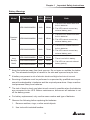
The power behind competitiveness
Delta UPS - Amplon Family
N Series, Single Phase
1/ 2/ 3 kVA
User Manual
www.deltapowersolutions.com
Save This Manual
This manual contains important instructions and warnings that you should
follow during the installation, operation, storage and maintenance of this
product. Failure to heed these instructions and warnings will void the warranty.
Copyright © 2015 by Delta Electronics Inc. All Rights Reserved. All rights of this
User Manual (“Manual”), including but not limited to the contents, information,
and figures are solely owned and reserved by Delta Electronics Inc. (“Delta”).
The Manual can only be applied to the operation or the use of this product. Any
disposition, duplication, dissemination, reproduction, modification, translation,
extraction, or usage of this Manual in whole or in part is prohibited without the prior
written permission of Delta. Given that Delta will continuously improve and develop
the product, changes may be made to the information in this Manual at any time
without obligation to notify any person of such revision or changes. Delta will make
all possible efforts to secure the accuracy and the integrity of this Manual. Delta
disclaims any kinds or forms of warranty, guarantee, or undertaking, either expressly
or implicitly, including but not limited to the completeness, faultlessness, accuracy,
non-infringement, merchantability or fitness for a particular purpose of the Manual.
Amplon N Series
II
Table of Contents
Table of Contents
Chapter 1 : Important Safety Instructions---------------------------- 1
1.1
Safety Instructions----------------------------------------------- 1
1.2Storage-------------------------------------------------------------- 4
Chapter 2 : Introduction---------------------------------------------------- 5
2.1
General Overview------------------------------------------------ 5
2.2
Exterior & Dimensions------------------------------------------ 5
2.3
Package List------------------------------------------------------- 6
Chapter 3 : Operation Panel----------------------------------------------- 8
3.1
LED Indicators---------------------------------------------------- 8
3.2
Multi-function Buttons------------------------------------------- 9
3.3
LCD Display------------------------------------------------------ 11
3.4
7-Segment Display----------------------------------------------14
3.5
Flow Chart of the 7-Segment Display----------------------16
Chapter 4 : Rear Panel-----------------------------------------------------18
Chapter 5 : Operation Modes--------------------------------------------20
5.1
Standby Mode----------------------------------------------------20
5.2
On-line Mode ----------------------------------------------------20
5.3
Bypass Mode-----------------------------------------------------20
5.4
Battery Mode-----------------------------------------------------20
5.5
Setup Mode ------------------------------------------------------21
Chapter 6 : Turn-on & Turn-off Procedures-------------------------23
6.1
Turn-on Procedures---------------------------------------------23
6.1.1 Normal Start-up----------------------------------------------------------23
6.1.2 Cold Start------------------------------------------------------------------23
6.2
Turn-off Procedures---------------------------------------------24
Chapter 7 : Alarm------------------------------------------------------------25
Chapter 8 : Optional Accessories--------------------------------------26
III
Chapter 9 : Troubleshooting---------------------------------------------27
Chapter 10 : Maintenance-------------------------------------------------30
10.1UPS-----------------------------------------------------------------30
10.2Batteries-----------------------------------------------------------30
10.3Fan------------------------------------------------------------------31
Appendix 1 : Technical Specifications-------------------------------32
Appendix 2 : Warranty-----------------------------------------------------34
Amplon N Series
IV
Chapter 1 Important Safety Instructions
Chapter 1 : Important Safety Instructions
1.1 Safety Instructions
Installation Warnings
zz
efore installation and usage, please read this User Manual thoroughly. This
B
helps you to use the product correctly and safely.
zz
Install the UPS in a well-ventilated area, away from excess moisture, heat, dust,
flammable gas or explosives.
zz
o avoid fire accidents and electric shock, please install the UPS in a temperT
ate and humidity well-controlled indoor area free of conductive contaminants.
For the temperature and humidity specifications, please refer to Appendix 1 :
Technical Specifications.
zz
eave adequate space (at least 15cm) around all sides of the UPS for proper
L
ventilation.
Connection Warnings
zz
The UPS must be well grounded due to a possible risk of current leakage.
zz
The installation of upstream and downstream protective devices is highly recommended when the UPS is connected to the mains and the loads.
zz
The protective devices connecting to the UPS must be installed near the UPS
and must be easily accessible for operation.
zz
Do not use extension cords to connect the UPS to an AC outlet.
zz
Do not plug the UPS’s input power cord (provided) into its own output sockets.
zz
If you need to move the UPS or perform re-wiring, please turn off the AC input
power and ensure that the UPS has been safely shutdown. Otherwise, the output end might still be energized, which might cause electric shock.
zz
The UPS output cable should be shorter than 10m.
1
Usage Warnings
zz
his is a class-A product. In a domestic environment, this product may cause raT
dio interference, in which case, the user is required to take adequate measures.
zz
he UPS can be used to power computers and associated peripheral devices,
T
such as monitors, modems, cartridge tape drives, external hard drives, etc.
zz
It is strictly forbidden to connect the UPS with:
1. any regenerative-type loads.
2. any asymmetrical loads (ex. half-wave rectifier).
zz
To ensure reliable operation of the UPS and to protect the UPS from overheating, the slits and openings in the UPS must not be blocked or covered.
zz
Before usage, you must allow the UPS to adjust to room temperature for at least
one hour to avoid moisture condensing inside the UPS.
zz
Do not pour and splash any liquid on the UPS. Do not insert any object into
the UPS’s slits and openings. Do not put beverage containers on or around the
UPS.
zz
When an emergency occurs, press the OFF button ( ) and release it after
you hear one beep to turn off the UPS. Cut off the input power to completely
shut down the UPS.
zz
Do not use any cleaning liquid or cleaning spray to clean the UPS. Before cleaning, please make sure that the UPS has been completely shut down, the UPS’s
input power cord has been unplugged, and the built-in batteries have been disconnected.
zz
All maintenance services must be performed by qualified service personnel.
Forbid opening or removing the cover of the UPS to avoid high voltage electric
shock.
zz
You must contact qualified service personnel if either of the following events occur:
1. Liquid is poured or splashed on the UPS.
2. The UPS does not run normally after this User Manual is carefully
observed.
NOTE : If you use the UPS in an area that generates or incurs dust, you should
install a dust filter in the UPS to ensure normal product life and function.
Amplon N Series
2
Chapter 1 Important Safety Instructions
Battery Warnings
Model
Device No.
UPS102N2000N0B0
Standard
Model
Long
Backup
Model
UPS202N2000N0B0
UPS Battery
Rating Voltage
1kVA
24Vdc
2kVA
48Vdc
UPS302N2000N0B0
3kVA
72Vdc
UPS102N2002N0B0
1kVA
24Vdc
UPS202N2002N0B0
2kVA
48Vdc
UPS302N2002N0B0
3kVA
72Vdc
Note
1. There are two sealed lead-acid
built-in batteries.
2. The UPS cannot connect any
external battery pack.
1. There are four sealed lead-acid
built-in batteries.
2. The UPS cannot connect any
external battery pack.
1. There are six sealed lead-acid
built-in batteries.
2. The UPS cannot connect any
external battery pack.
1. There is no built-in battery.
2. The UPS can connect external
battery pack(s).
zz
Keep the batteries away from heat sources. Do not open or mutilate the batteries. The released electrolyte is harmful to the skin and eyes and may be toxic.
zz
A battery can present a risk of electric shock and high short-circuit current.
zz
Servicing of batteries must be performed or supervised by qualified service personnel knowledgeable in batteries and the required precautions. Keep unauthorized personnel away from batteries.
zz
The risk of electric shock and short-circuit current is possible when the batteries
are connected to the UPS. Before maintenance, disconnect all batteries to cut
off the battery power.
zz
For battery replacement, only use the same number and type of batteries.
zz
Observe the following before replacing the batteries:
1. Remove watches, rings, or other metal objects.
2. Use tools with insulated handles.
3
3. Wear rubber gloves and boots.
4. Do not lay tools or metal parts on the top of batteries.
5. Before battery removal, replacement or installation, disconnect any circuit
connected to the batteries.
zz
Do not connect the batteries in reverse; otherwise, a risk of electric shock or fire
accidents might occur.
WARNING:
The risk of electric shock and short-circuit current is possible when
the batteries are still connected to the UPS even though the UPS is
disconnected from the mains. Do not forget to cut off the battery source
before maintenance.
1.2Storage
zz
Prior to installation
If the UPS needs to be stored prior to installation, it should be placed in a
dry area. The allowable storage temperature is between -15°C and +50°C
(5°F~122°F).
zz
After usage
button, make sure the UPS is shutdown, disconnect the UPS from
Press the
the utility power, remove all equipment from the UPS, and store the UPS in a dry
and well-ventilated area at a temperature between -15°C and +50°C (5°F~122°F).
Idle batteries must be recharged fully approximately every three months if the
UPS needs to be stored for an extended period of time. The charging time must
not be less than 24 hours each time.
NOTE : After storage and before start-up of the UPS, you must allow the UPS to
adjust to room temperature (20°C~25°C or 68°F~77°F) for at least one
hour to avoid moisture condensing inside the UPS.
Amplon N Series
4
Chapter 2 Introduction
Chapter 2 : Introduction
2.1 General Overview
The N series UPS is a single-phase on-line UPS providing reliable and consistent
sine-wave quality power to your electronic equipment. It adopts the latest technology and the highest quality components providing output power factor up to 0.9 and
its efficiency in on-line mode can reach at maximum 93%. The UPS not only provides safe, reliable and uninterrupted power to your sensitive electronic equipment
at all times, but also produces greater electronic power efficiency at less cost. Its
compact design does not occupy much space and is easy to use. There are three
different ratings (1kVA, 2kVA and 3kVA) for your selection.
2.2 Exterior & Dimensions
325mm
225mm
14
m
5m
0m
m
32
19
0m
(Figure 2-1 : 1 kVA
Exterior & Dimensions)
m
(Figure 2-2 : 2/3 kVA
Exterior & Dimensions)
5
m
0m
39
2.3 Package List
NOTE : 1. If there is any damage or anything missing, please immediately contact
the dealer from whom you purchased the unit.
2. If the UPS needs to be returned, carefully repack the UPS and all of the
accessories using the original packing material that came with the unit.
zz
Standard Model: UPS102N2000N0B0 (1kVA)/ UPS202N2000N0B0 (2kVA)/
UPS302N2000N0B0 (3kVA):
1
2
SETUP
No.
ON
3
4
OFF
Item
Q’ty
1
UPS
1 PC
2
User Manual
1 PC
3
Terminal Copper *1
4
Cable Tie *1
1/ 2kVA
3kVA
3 PCS
1 PC
*1:The terminal copper (3 PCS) and cable tie (1 PC) are used to connect the
UPS output terminals ( L, N, ) located at the rear of the 3kVA UPS.
Amplon N Series
6
Chapter 2 Introduction
zz
ong Backup Model: UPS102N2002N0B0 (1kVA)/ UPS202N2002N0B0
L
(2kVA) / UPS302N2002N0B0 (3kVA):
1
SETUP
ON
2
4
3
5
OFF
6
7
No.
Item
Q’ty
1
UPS
1 PC
2
User Manual
1 PC
3
Terminal Copper *1
4
Cable Tie (Type A) *11
1 PC
5
Cable Tie (Type B) *2
1 PC
6
Battery Wire
1 PC
7
Ring-type Thimble *2
2 PCS
8
Joint *
2 PCS
9
Wire Mount *2
8
1/ 2kVA
9
3kVA
3 PCS
2
1 PC
*1:The terminal copper (3 PCS) and cable tie (Type A: 1 PC) are used to
connect the UPS output terminals ( L, N, ) located at the rear of the 3kVA
UPS.
*2:If the provided battery wire (1 PC) is not long enough and you want to use
a longer battery wire (not provided), please use the provided joint (2 PCS),
ring-type thimble (2 PCS), cable tie (Type B: 1 PC) and wire mount (1 PC) to
join them together.
7
Chapter 3 : Operation Panel
3.1 LED Indicators
!
IN
OUT
RUN TIME
SET TEST BATT LOAD
3.3 LCD Display (inclduing
3.4 7-Segment Display)
V%
Hz
KVA
KW
MIN
°C
3.2 Multi-function Buttons
SETUP
ON
OFF
3.1 LED Indicators
No.
LED
1
Description
Indicates the output status.
1.ON (green): There is output
2.OFF: There is no output
2
1.ON (red): The UPS detects an internal fault or an environmental
fault. You could refer to 3.3 LCD Display - No. 9 for more information.
2.Flashing (red): The UPS has the following warning message(s).
a. :There is no battery or battery replacement is needed.
b.
Amplon N Series
:The UPS is overloaded.
8
Chapter 3 Operation Panel
3.2 Multi-function Buttons
MultiNo. function
Button
1
Description
The button has multi-function. Please refer to the following for detailed information.
1.Turn-on:
zz In
standby/ bypass mode, press and hold the button for 3 seconds, release it after you hear one beep and the UPS will run
in on-line mode.
zz Cold
start: When there is no AC input, press and hold the button for 3 seconds, release it after you hear one beep and the
UPS will start up in battery mode.
2.Battery Test:
Battery test can only be executed in on-line mode.
zz For
automatic regular battery test, you must install the Virtual
COM Port Driver and the UPSentry 2012 software (please
download from http://59.125.232.140) or configure the SNMP
card (optional) or ModBus card (optional).
zz For
manual battery test, please press and hold the button for
3 seconds, release it after you hear one beep, and the UPS
will transfer to run in battery mode and perform a 10-second
battery test.
If the test result is ok, the LCD will show ‘PAS’ and the UPS
will return to on-line mode.
If the test result is abnormal, the LCD will show ‘FAL’, the
LED
will flash, the warning icon
and no-battery/ battery
replacement icon will illuminate, and the UPS will return to
on-line mode.
3.Buzzer Off:
When the buzzer is on, press the button for 0.1 second to turn
the buzzer off. Please note that the buzzer will automatically
turn on when a new alarm occurs. The buzzer can’t be manually
turned on after it has been muted.
4.Confirmation:
In setup mode, press the button for 0.1 second to confirm your
parameter setup.
9
MultiNo. function
Button
2
Description
The button has multi-function. Please refer to the following for detailed information.
1.Turn-off:
zz In
on-line mode, press and hold the button for 3 seconds,
release it after you hear one beep and the inverter will be off
and the UPS will transfer to run in standby/ bypass mode.
The UPS will keep charging the batteries when the UPS is
in standby/ bypass mode even though the button has been
pressed. To fully turn off the UPS, it is advised to unplug the
input power cord.
zz In
battery mode, press and hold the button for 3 seconds, release it after you hear one beep and the UPS will turn off its
output.
2.Fault Clear:
When the UPS has a fault condition, press and hold the button
for 3 seconds, release it after you hear one beep and the UPS
will clear the fault condition and return to standby/ bypass mode.
Besides, the LCD will show the relevant error code. For error
code information, please refer to 3.3 LCD Display - No. 9.
3
The button has multi-function. Please refer to the following for detailed information.
1.Scrolling down:
Press the button for 0.1 second to go to the next display.
2.Entering into the setup mode:
Press the button for 3 seconds and the UPS will enter into the
setup mode. For more information, please refer to 5.5 Setup
Mode. Please note that only qualified service personnel can perform setup action.
NOTE : When the backlight of the LCD is off, you can press any button mentioned
above to wake up the display and enable each button function.
Amplon N Series
10
Chapter 3 Operation Panel
3.3 LCD Display
!
IN
OUT
RUN TIME
SET TEST BATT LOAD
V%
Hz
KVA
KW
MIN
°C
No.
1
Icon
Naming
AC Icon
Description
Indicates the input source status.
1.ON: The AC input is within the acceptable
bypass range.
2.Flashing: The AC input is out of the acceptable bypass range but is still sufficient to let
the unit operate in on-line mode.
3.OFF: The AC input is out of the acceptable
bypass range and is not sufficient to let the
unit operate in on-line mode.
2
Output Icon
Indicates the output status.
1.ON: There is output.
2.OFF: There is no output.
3
Battery
Power Icon
Indicates the battery power status.
1.ON: Battery power is on.
2.OFF: Output is not supplied by the battery
power.
4
Standby
Mode Graph
Illuminates when the UPS is operating in standby mode.
5
Online Mode
Graph
Illuminates when the UPS is operating in on-line
mode.
11
No.
Icon
Naming
Description
6
Battery
Mode Graph
Illuminates when the UPS is operating in battery
mode.
7
Bypass
Mode Graph
Illuminates when the UPS is operating in bypass
mode.
8
Buzzer Icon
Illuminates when the buzzer is disabled.
9
Warning Icon 1.ON:
The unit is shut down due to an internal fault
or an environmental fault. The error code will
appear on the 7-segment display. Please refer
to the following table for each error code and
refer to 3.4 7-Segment Display for relevant
7-segment display information.
Error Code
Meaning
E11
Charger Fault
E13
Temperature Out of Range
E14
+/- DC BUS High/ Low
E16
Inverter Fault
E18
DC-DC Fault
E19
Abnormal Output/ Inverter
Voltage
E21
O/P Short
Sd1
RPO Shutdown
Sd4
Battery Low Shutdown
2.Flashing:
When the icon is flashing, it would be accompanied with other icon(s) to show you the
according warning message(s).
a.
:There is no battery or battery replacement is needed.
b.
Amplon N Series
:The UPS is overloaded.
12
Chapter 3 Operation Panel
No.
Icon
10
Naming
Load Level
Bar Graph
Description
Indicates the status of load level.
1.ON:
The bar graph illuminates according to the
load level *1.
2.Flashing:
The bar graph flashes when there is an
overload situation.
11
Battery Level Indicates the status of battery level.
Bar Graph
1.ON:
The bar graph illuminates according to the remaining battery capacity *1.
2.Flashing:
The bar graph flashes when a low-battery
situation occurs.
NOTE : *1 means that:
<10%: no segment will illuminate.
10%-29%: the 1st segment will illuminate.
30%-49%: the first two segments will illuminate.
50%-69%: the first three segments will illuminate.
70%-89%: the first four segments will illuminate.
90%-100%: all segments will illuminate.
13
3.4 7-Segment Display
Column A
!
IN
OUT
RUN TIME
SET TEST BATT LOAD
V%
Hz
KVA
KW
MIN
°C
7-Segment Display
Column B
NOTE : You might need to read the word shown in Column A together with that in
Cloumn B to understand the display meaning.
No.
Icon
1
IN
Description
1.IN & V:
When the above two words illuminate together, it means
input voltage.
2.IN & Hz:
When the above two words illuminate together, it means
input frequency.
2
OUT
1.OUT & V:
When the above two words illuminate together, it means
output voltage.
2.OUT & Hz:
When the above two words illuminate together, it means
output frequency.
3
RUN TIME
Amplon N Series
RUNTIME & MIN:
When the above two words illuminate together, it means the
estimated remaining backup time.
14
Chapter 3 Operation Panel
No.
Icon
Description
4
SET
When the word ‘SET’ illuminates, it means that the UPS is in
the setup mode.
You can set up the following items via the LCD. For how to
setup, please refer to 5.5 Setup Mode.
1.Inverter voltage
2.Inverter frequency
3.Bypass range
4.Buzzer
5.Overload alarm
5
TEST
1.When the word ‘TEST’ flashes, it means that the UPS is
under test.
2.When the two words ‘TEST’ and ‘BATT’ flash together, it
means that the UPS is under battery test.
6
BATT
1.BATT & %:
When the above two words illuminate together, it means
the remaining battery capacity.
2.BATT & V:
When the above two words illuminate together, it means
battery voltage.
7
LOAD
1.LOAD & %:
When the above two words illuminate together, it means
how much the total load has occupied the rated capacity.
2.LOAD & KVA:
When the above two words illuminate together, it means
how much kVA the total load is.
3.LOAD & KW:
When the above two words illuminate together, it means
how much kW the total load is.
4.LOAD & % &
:
flash
When the above word (LOAD), unit (%) and icon
together, it means that the UPS has an overload situation.
15
No.
Icon
8
V
9
Description
Means ‘voltage’.
Means ‘percentage’.
10
Hz
11
kVA
Means ‘kVA’.
12
kW
Means ‘kW’.
13
MIN
Means ‘minute’.
14
Means ‘frequency’.
Means the UPS’s internal temperature.
3.5 Flow Chart of the 7-Segment Display
The following flow chart helps you to understand how to go through each display
screen. Here, we take ‘Standby Mode’ as an example. Each of the display diagrams
shown in below is for reference only. Actual display depends on the operation of the
UPS.
After this screen appears around 10
seconds, the scrolling function will be
active. The scrolling button is
.
Amplon N Series
16
Chapter 3 Operation Panel
Press the
button
for 0.1 second to view
the next display.
SETUP
Press the
button for 0.1
second to view the next display.
Press the
button for 0.1
second to view the next display.
Press the
button for 0.1
second to view the next display.
Press the
button for 0.1
second to view the next display.
Press the
button for 0.1
second to view the next display.
Press the
button for 0.1
second to view the next display.
Press the
button for 0.1
second to view the next display.
Press the
button for 0.1
second to view the next display.
Press the
button
for 0.1 second to
view the next display.
Press the
button
for 0.1 second to
view the next display.
17
Chapter 4 : Rear Panel
Standard Model: UPS102N2000N0B0 (1kVA)/ UPS202N2000N0B0 (2kVA)/
UPS302N2000N0B0 (3kVA):
1
4
1
4
MINI SLOT
2
5
OUTPUT SOCKET
1
4
MINI SLOT
OUTPUT SOCKET
MINI SLOT
2
5
5
2
L
IN P U T B R E A K E R
10A
OUTPUT SOCKET
6
AC INPUT
3
7
6
IN P U T B R E A K E R
20A
3
7
AC INPUT
E X T E R N A L B A T T .C O N N E C T O R
E X T E R N A L B A T T .C O N N E C T O R
1 kVA
No.
UPS OUTPUT
3
2 kVA
Item
N
8
E X T E R N A L B A T T .C O N N E C T O R
zz
IN P U T B R E A K E R
20A
AC INPUT
3 kVA
Functions
1
Mini Slot
Accepts a mini SNMP, mini Relay I/O, mini ModBus or
mini TVSS card (optional).
2
Output Sockets
Connect to your loads.
3
External Battery
Pack Connector
N/A. The UPS cannot connect any external battery
pack.
4
USB Port
Connects to your computer. You can monitor the UPS’s
status via your computer by installing the Virtual COM
Port Driver and the UPSentry 2012 software (please
download from http://59.125.232.140).
5
Fan(s)
Cool(s) and ventilate(s) the UPS.
6
Input Breaker
It is the input power’s protective device. It is for safety
protection.
7
AC Input Cord
Connects to a wall socket.
8
UPS Output
Terminals
Connect to your loads.
Amplon N Series
18
6
7
Chapter 4 Rear Panel
Long Backup Model: UPS102N2002N0B0 (1kVA)/ UPS202N2002N0B0
(2kVA)/ UPS302N2002N0B0 (3kVA):
1
4
1
4
MINI SLOT
2
5
OUTPUT SOCKET
1
4
MINI SLOT
OUTPUT SOCKET
MINI SLOT
2
5
5
2
L
IN P U T B R E A K E R
10A
OUTPUT SOCKET
6
AC INPUT
3
7
6
IN P U T B R E A K E R
20A
3
7
AC INPUT
E X T E R N A L B A T T .C O N N E C T O R
E X T E R N A L B A T T .C O N N E C T O R
1 kVA
No.
UPS OUTPUT
3
2 kVA
Item
N
8
E X T E R N A L B A T T .C O N N E C T O R
zz
IN P U T B R E A K E R
20A
AC INPUT
6
7
3 kVA
Functions
1
Mini Slot
Accepts a mini SNMP, mini Relay I/O, mini ModBus or
mini TVSS card (optional).
2
Output Sockets
Connect to your loads.
3
External Battery
Pack Connector
Connects to the external battery pack(s). There are +, -,
and terminals.
4
USB Port
Connects to your computer. You can monitor the UPS’s
status via your computer by installing the Virtual COM
Port Driver and the UPSentry 2012 software (please
download from http://59.125.232.140).
5
Fan(s)
Cool(s) and ventilate(s) the UPS.
6
Input Breaker
It is the input power’s protective device. It is for safety
protection.
7
AC Input Cord
Connects to a wall socket.
8
UPS Output
Terminals
Connect to your loads.
19
Chapter 5 : Operation Modes
NOTE : 1. Please refer to Chapter 3 : Operation Panel to learn how to operate the
operation panel and understand the display meaning.
2. Each of the display diagrams shown in this chapter is for reference only.
Actual display depends on the operation of the UPS.
5.1 Standby Mode
After the UPS is connected to the AC utility, it will supply power to the UPS and the
batteries will be charged. The default setting of the UPS is set in ‘STANDBY mode’.
5.2 On-line Mode
In online mode, the connected loads are supplied by the inverter, which derives its
power from the utility AC power, and the UPS charges the batteries and provides
power protection to its connected loads.
5.3 Bypass Mode
In bypass mode, the critical loads are directly supplied by the utility power and the
batteries are charged.
5.4 Battery Mode
When the UPS is operating during a power outage, the batteries provide DC power,
which maintains inverter operation to support the connected critical loads.
You can install the Virtual COM Port Driver and the UPSentry 2012 software (please
download from http://59.125.232.140) or configuare the SNMP card (optional) or
ModBus card (optional) to monitor and estimate the battery remaining capacity
before or during an AC power failure. For more information about the SNMP card
(optional) or ModBus card (optional), please refer to its user manual.
NOTE : You can only enable ‘SHUTDOWN AFTER’ function in battery mode. For
information about ‘SHUTDOWN AFTER’ function, please contact service
personnel.
Amplon N Series
20
Chapter 5 Operation Modes
5.5 Setup Mode
Press the scrolling button setup menu.
for more than 3 seconds and the LCD will go into the
Please note that only qualified service personnel can perform setup action. In setup
mode, you can set up the following items:
1. Inverter voltage
2. Inverter frequency
3. Bypass range
4.Buzzer
5. Overload alarm
For setup procedures, please refer to the following:
1. Press the scrolling button mode.
2. Press the scrolling button for more than 3 seconds to enter into the setup
for 0.1 second to change the parameter.
3. Press the confirmation button
for 0.1 second to confirm your parameter, and
at the same time, the LCD will go to the next setup item.
4. You can skip to the next setup item by pressing the cancel button
second.
5. In setup mode, press the scrolling button
will go back to the original display.
for 0.1
for more than 3 seconds, the LCD
6. In setup mode, if you don’t press any button for more than 2 minutes, the LCD
will exit from the setup mode and go back to the original display automatically.
For some settings, they can’t be set in certain operation modes. Please refer to the
table below for relevant information.
Setup
Item
Standby
Mode
Inverter Voltage Setup
Inverter Frequency Setup
Bypass Range Setup
21
On-line
Mode
Bypass
Mode
Battery
Mode
Setup
Item
Standby
Mode
On-line
Mode
Bypass
Mode
Battery
Mode
Buzzer Setup
Overload Alarm Setup
NOTE : Please note that only qualified service personnel can perform setup
action.
Setup Mode Flow Chart
Original Display
T>3 seconds
Inverter Voltage Setup
T>3 seconds
T>0.1S
T=0.1S
T>0.1S
Inverter Frequency Setup
T>3 seconds
T>0.1S
T=0.1S
T>0.1S
Bypass Range Setup
T>3 seconds
T>0.1S
T=0.1S
T>0.1S
Buzzer Setup
T>3 seconds
T>0.1S
T=0.1S
T>0.1S
Overload Alarm Setup
T>3 seconds
T=0.1S
Amplon N Series
T>0.1S
22
Chapter 6 Turn-on & Turn-off Procedures
Chapter 6 : Turn-on & Turn-off Procedures
NOTE : Please refer to Chapter 3 : Operation Panel to learn how to operate the
operation panel and understand the display meaning.
WARNING:
Before performing turn-on procedures:
1. Please check the ‘+’ and ‘-’ poles and ensure that battery wring is correct
(only for long backup model).
2. Please connect the external battery pack(s) with the UPS (only for long
backup model).
6.1 Turn-on Procedures
6.1.1 Normal Start-up
1. Verify if the UPS’s input cord meets with N, L & G of the wall socket.
2. After the UPS is connected to the AC utility, the AC utility supplies power to the
UPS. The UPS is initially set in ‘STANDBY mode’. To turn on the UPS, press and
hold the
button for 3 seconds and release it after you hear one beep.
NOTE : After installation and before 1st start-up of the UPS, please ensure that
the AC utility is normal (even though the UPS has the cold-start function).
6.1.2 Cold Start
Even when there is no utility power, you can still turn on the UPS. Just press and
button for 3 seconds, release it after you hear one beep, and the UPS
hold the
will start up and run in battery mode.
23
6.2 Turn-off Procedures
NOTE : Before performing turn-off procedures, verify that all of the loads connected
to the UPS have been safely shutdown.
button
1. In on-line mode, if you want to turn off the UPS, press and hold the
for 3 seconds and release it after you hear one beep. The inverter will turn off
and the UPS will transfer to standby/ bypass mode.
The UPS will keep charging the batteries when the UPS is in standby/ bypass
mode even though the
button has been pressed. To fully turn off the UPS, it
is advised to unplug the input power cord.
button
2. In battery mode, if you want to turn off the UPS, press and hold the
for 3 seconds and release it after you hear one beep. The UPS will turn off its
output. For long backup model, disconnecting the wiring between the UPS and
the external battery pack(s) is suggested.
Amplon N Series
24
Chapter 7 Alarm
Chapter 7 : Alarm
No.
Condition
Alarm
1
Battery Mode
The audible alarm beeps once every 2.1 seconds.
2
Low Battery
The audible alarm beeps once every 0.6 second.
3
Battery
Missing/ Weak
Battery/ Battery
Replacement/ *
The audible alarm beeps once every 2.1 seconds.
4
Overload
1. Overload_105%~125%: The audible alarm beeps
once every 2.1 seconds.
2. Overload_125%~150%: The audible alarm beeps
once every 0.6 seconds.
5
Fault
The audible alarm beeps continuously for 5 seconds
when the UPS detects an internal fault.
NOTE : *: After reconnecting or replacing the batteries, it might take a while for
the UPS to switch off the alarm automatically. If, after a period of time, the
audible alarm still exists, the user must manually initiate a battery test (press
button for 3 seconds and release it after you hear one beep)
and hold the
to clear the alarm.
25
Chapter 8 : Optional Accessories
No.
Item
Function
1
Dust Filter
Prevents dust from entering into the UPS to
ensure UPS reliability and to prolong product life.
2
Mini SNMP Card
Monitors and controls the status of the UPS via a
network system.
3
Mini Relay I/O Card
Increases the quantity of dry contacts.
4
Mini ModBus Card
Lets the UPS have ModBus communication
function.
5
Mini TVSS Card
Lets the UPS have surge protection function.
6
Charger Board-4A
(only for Long Backup
Model)
Additionally install the 4A charger board to
increase the charge current to reach at maximum
8A.
NOTE : 1. For detailed installation and operation of any accessory mentioned above,
please refer to the Quick Guide, User Guide, or Installation & Operation
Guide included in the package of the relevant optional accessory.
2. If you want to buy any accessory mentioned above, please contact your
local dealer or customer service.
Amplon N Series
26
Chapter 9 Troubleshooting
Chapter 9 : Troubleshooting
1. When a problem occur, please check if the following situation exists before
contacting Delta service personnel:
zz
Is the main input voltage present?
2. Please have the following information ready if you would like to contact the Delta
service personnel:
zz
Unit information including model, serial number, etc.
zz
n exact description of the problem. The more detailed description of the
A
problem, the better.
3. When you see the following problems occur, please follow the solutions shown
below.
A. About the error codes shown on the 7-segment Display:
Error
Code
Meaning
Possible
Cause
Solution
E11
Charger
Fault
Charger is damaged.
Contact service personnel.
E13
Temperature
Out of
Range
The UPS temperature
is out of range.
1. Check whether the UPS’s
ventilation is normal.
2. Decrease the loads.
3. Check whether the fan(s)
run(s) normally.
4. Clean the filters (if you
have installed any).
E14
+/- DC BUS
High/ Low
The UPS has
abnormalities.
27
Contact service personnel.
Error
Code
Meaning
Possible
Cause
Solution
E16
Inverter
Fault
The UPS has
abnormalities.
Contact service personnel.
E18
DC-DC Fault
The UPS has
abnormalities.
Contact service personnel.
E19
Abnormal
Output/
Inverter
Voltage
The UPS has
abnormalities.
Contact service personnel.
E21
O/P Short
Output has a shortcircuit issue.
1. Check whether the output
has a short-circuit issue.
2. Contact service personnel.
Sd1
RPO
Shutdown
Remote shutdown
is executed from dry
contact.
After the remote shutdown
events are eliminated, follow
the turn-on procedures to
start up the UPS.
Sd4
Battery Low
Shutdown
The UPS transfers to
run in battery mode
due to AC utility
abnormality; however,
the battery power is
almost used up.
1. Check the main AC source
and the input power cord’s
status.
Amplon N Series
28
2. Contact service personnel.
Chapter 9 Troubleshooting
B. About other problems that might happen:
No.
Problem
Possible Cause
Solution
Decrease your connected
loads.
1
Overload
The UPS is
overloaded.
2
Battery Missing
Internal battery cables 1. Contact service
personnel.
are not connected or
not firmly connected.
2. Connect the internal
battery cables and
connect them firmly.
3
Weak Battery/
Battery
Replacement
Batteries are
damaged or battery
life time is due.
4
Abnormal Input
(when the AC icon
is flashing)
1. Check whether the
The AC input voltage
AC input voltage or
or frequency is out of
frequency is abnormal.
the acceptable bypass
range.
2. Contact service
personnel.
Contact service personnel.
NOTE : If all possible causes are eliminated but the alarm still appears, please
contact your local dealer or customer service.
29
Chapter 10 : Maintenance
10.1UPS
zz
UPS Cleaning
Regularly clean the UPS, especially the slits and openings, to ensure that the
air freely flows into the UPS to avoid overheating. If necessary, use an air-gun
to clean the slits and openings to prevent any object from blocking or covering
these areas.
zz
UPS Regular Inspection
Regularly check the UPS every half year and inspect:
1. Whether the UPS, LEDs, and alarm function are operating normally.
2. Whether battery voltage is normal. If battery voltage is too high or too low,
find the root cause.
10.2Batteries
The N series UPS uses sealed lead-acid batteries. Though the typical battery life
cycle is 3~5 years, the battery life depends on the temperature, the usage, and the
charging/ discharging frequency. High temperature environments and high charging/
discharging frequency will quickly shorten the battery life. The UPS does not require
maintenance by the user; however, the batteries should be checked periodically.
Please follow the suggestions below to ensure a normal battery lifetime and
sufficient back-up time.
zz
Keep the usage temperature at 20°C ~25°C.
zz
Idle batteries must be fully recharged every three months if the UPS needs to be
stored for an extended period of time. Please fully charge the batteries (internal
and external) until the Battery Level Bar Graph
fully on.
zz
shown on the UPS’s LCD is
A loss of battery charge capacity may occur during shipping and storage. Before
1st use of the UPS, please fully charge the batteries (internal and external).
NOTE: If the UPS’s internal batteries need to be replaced, please
contact qualified service personnel. During battery replacement, the
loads attached to the UPS will not be protected if input power fails.
Amplon N Series
30
Chapter 10 Maintenance
10.3Fan
Higher temperatures shorten fan life. When the UPS is running, please check if
each fan works normally and make sure if the ventilation air can move freely around
and through the UPS. If not, contact service personnel.
NOTE : Please ask your local dealer or customer service for more maintenance
information. Do not perform maintenance if you are not trained for it.
31
Appendix 1 : Technical Specifications
Model
Power
Rating
N-1K
N-2K
N-3K
Standard Model
1kVA/0.9KW
2kVA/1.8KW
3kVA/2.7KW
Long Backup Model
1kVA/0.8KW
2kVA/1.6KW
3kVA/2.4KW
Waveform
Input
Pure Sine Wave
Nominal Voltage
220/230/240 Vac
Voltage Range
175 ~ 280 Vac (100% load);
80 ~ 175 Vac (50% ~ 100% load)
Frequency
50/60 Hz ± 10 Hz
Power Factor
> 0.99 (full load)
iTHD
< 3%
0.9 (Standard Model)
Power Factor
Output
0.8 (Long Backup Model)
Voltage
220/230/240 Vac
Voltage
Regulation
± 2% (linear load)
Frequency
50/60 Hz ± 0.05 Hz
vTHD
< 3% (linear load)
Overload
Capability
< 105%: continuous; 105% ~ 125%: 1 minute; 125% ~ 150%: 30 seconds
Cress Factor
3:1
Connection
India
socket x 3
Efficiency
Online Mode
91%
Battery
Battery Voltage
24 Vdc
Amplon N Series
32
India
socket x 4
India socket
x 4, Terminal
block x 1
Up to 93%
48 Vdc
72 Vdc
Appendix 1 Technical Specifications
Model
N-1K
Backup Time
(Standard) *
N-2K
N-3K
Standard Model: Up to 7 Min.
Standard Model: 3hrs to 90%
Recharge Time
Battery
Long Backup Model: Depends on the capacity of the connected external battery pack(s)
Standard Model: 1A
Charge Current
Audible Noise
Long Backup Model: 4A
(can be increased to 8A via installation
of 4A charge board (optional))
< 43 dBA
< 48 dBA
< 48 dBA
Display
LED indicators & LCD display
Communication Interfaces
MINI Slot x 1, USB Port x 1
Dimensions
145 x 320 x
225 mm
190 x 390 x
325 mm
190 x 390 x
325 mm
Standard
Model
9.7 Kg
19.1 Kg
24.9 Kg
Long Backup
Model
4.4 Kg
8.2 Kg
8.5 Kg
(W × D × H )
Physical
Weight
Operating Altitude
Environment
1000 meters (without derating)
Operating
0 ~ 40°C
Temperature
Relative Humidity
5% ~ 95% (non-condensing)
NOTE : 1.
* : When the total load reaches 75% and 9Ah batteries are used.
2. Please refer to the rating label for the safety rating.
3. All specifications are subject to change without prior notice.
33
Appendix 2 : Warranty
Seller warrants this product, if used in accordance with all applicable instructions,
to be free from original defects in material and workmanship within the warranty
period. If the product has any failure problem within the warranty period, Seller will
repair or replace the product at its sole discretion according to the failure situation.
This warranty does not apply to normal wear or to damage resulting from improper
installation, operation, usage, maintenance or irresistible force (i.e. war, fire,
natural disaster, etc.), and this warranty also expressly excludes all incidental and
consequential damages.
Maintenance service for a fee is provided for any damage out of the warranty
period. If any maintenance is required, please directly contact the supplier or Seller.
WARNING!
The individual user should take care to determine prior to use whether the
environment and the load characteristic are suitable, adequate or safe for
the installation and the usage of this product. The User Manual must be
carefully followed. Seller makes no representation or warranty as to the
suitability or fitness of this product for any specific application.
Amplon N Series
34
5013231700