1
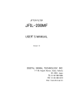
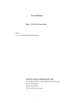
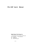
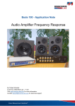
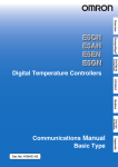
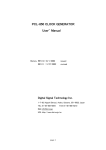
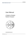
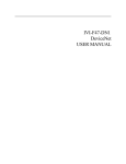
Programmable RF Signal Generator DPL-3.2GXF User’s Manual Digital Signal Technology, Inc. 1-7-30, Higashi Benzai, Asaka, Saitama 351-0022, Japan TEL : 81-48-468-6094 FAX : 81-48-468-6210 http://www.dst.co.jp. email : [email protected] DPL-3.2GXF User’s Manual Page1 DPL-3.2GXF is a wide band synthesizer utilizing 48 bit DDS(Direct Digital Synthesizer) and PLL(Phase Locked Loop) technique. It provides pure sine wave signal output from 5MHz-3.2GHz in 0.001Hz steps. The stable output level has been achieved in the range of -40dBm-+14dBm with ALC function. DPL-3.2GXF is having internal 10MHz clock reference and might be used as not only a stand-alone synthesizer but also the clock source for embedded system. In case the accurate 10MHz clock is available externally, the frequency stability can be improved. Parameter settings such as frequency, output level and so on can be controlled by serial data which is connected to PC communication port and can be memorized into EEPROM. An optional board , FIX-3.2GX is available to control any settings without using a PC. ■ Specification Power supply +4.75V~+7V 1.5A **Be careful with voltage drop of power supply line. If the supply voltage at power input terminal is lower than 5V, the maximum output level and spurious would be worse. Frequency range 5MHz~3200MHz Frequency resolution 0.001Hz Output level +14dBm~-40dBm RF OFF output level -60dBm or less Output level accuracy ±1dB or less(output level -30dBm or more) ±2dB or less(output level from under -30dBm ~-40dBm exclusive) Output level resolution 0.1dB Phase offset range -360.0°~+360.0° Phase offset resolution 0.1° Output impedance nominal 50Ω Spurious -60dBc or less DPL-3.2GXF User’s Manual Page2 Harmonic spurious -30dBc or less (When the output level is from +10dBm to -30dBm, and supply voltage is from 5V to 7V) Internal reference clock Frequency accuracy Long term frequency stability ±2.5ppm or less(0℃~+50℃) ±1ppm or less per year External reference input Frequency Input level Impedance 10MHz +6dBm(±3dB) 50Ω Interface Type Connector Asynchronous serial data RS-232C Use a straight cable for PC serial port D-Sub 9 pin Environmental condition Operating temperature range 0℃~+50℃ Dimension W100xH35xD100(mm) Weight 300g ■ Phase Noise(Typical) under the internal reference clock mode (Unit is in dBc) Freq.[Hz] 3G 1G 500M 250M 100M Offset from Carrier[Hz] 10 100 1K -63.7 -80.8 -93.0 -74.9 -93.1 -104.1 -78.5 -98.0 -110.6 -85.0 -103.2 -115.6 -92.5 -115.1 -125.9 DPL-3.2GXF User’s Manual 10K -90.5 -99.4 -105.5 -111.4 -123.6 100K -109.9 -115.0 -120.9 -126.0 -132.5 1M -136.1 -134.0 -134.1 -133.2 -132.8 10M -145.0 -135.2 -134.5 -133.3 -132.8 Page3 ■ Terminal DPL-3.2GXF User’s Manual Page4 1. 5V Power supply terminal Connect +5V ±5%the power supply having more than 1.5A current capacity . 2. Ground terminal Connect the ground of the power supply (Caution : Do not touch + side of the power supply to the ground. To use a heat shrinking tube is recommended for its protection) 3. External reference clock input terminal Apply 10MHz reference clock to this connector(SMA) which has 50Ω input impedance. The external clock mode must be selected. 4. RS-232C port This is a connector for serial communication for setting frequency and output level and so on. Interface is RS-232C. Use a D-sub9 pin(male)connector and a straight cable for PC serial port. 5. Output port This is a connector of output signal. Use SMA(male)connector. ■ Outline Dimension DPL-3.2GXF User’s Manual Page5 Mounting Holes M3-4PL Same mounting holes on the other side. Hole Depth 10mm ■ RS-232C port communication condition Type of communication Interface Level Communication speed Data length Stop bit Parity Flow control Asynchronous serial data RS-232C 9600BPS 8 bit 1 bit none none 9 pin D-Sub pin assignment Pin# 1 6 2 7 3 8 4 9 5 Signal name CD DSR RD RTS TD CTS DTR RI GND Signal direction DPL → terminal → → ← ← → ← → ←→ DPL-3.2GXF User’s Manual Remarks Not used Connected to DTR internally Connected to CTS internally Connected to RTS internally Connected to DSR internally PLL unlocked signal Page6 Pin#9 is an open drain output and used as a PLL unlocked signal. When PLL is locked : Low(Short to GND) When PLL is unlocked : High(Open) Please refer to the above table to set serial communication parameters of your terminal software. Any communication software such as Hyperterminal can be used. ■ How to control The following message is returned when DPL-3.2GXF is powered on. DPL-3.2GXF V1.0 MAIN MENU F_xx --------------A_xx --------------P_xx --------------ON ----------------OFF ---------------SAVE --------------SUB ---------------STS ---------------HELP --------------- Firm V1.0 Frequency SET Output Level SET Phase Offset SET Output ON Output OFF Frq&Level SAVE SUB MENU ENTRY STATUS MAIN MENU CONTENTS SYSTEM STATUS Frequency = 1 234 567 890.123 [Hz] Output Level = 0.0 [dBm] Phase Offset = +0.0 [Deg] Output = ON PLL LOCKED 10MHz Base Clock Source = Internal External Clock Synchronize = OFF * This is just a example. The status depends on how the unit is set After the prompt “*” (2Ahex) is returned, commands can be entered. There are two modes in command menu, main menu mode and sub menu mode. Frequency and output level setting can be done in main menu mode. System setting command such as setting 10MHz clock source can be done in sub menu mode. Enter space code (20hex) after each command to set a value, then enter return key (0Dhex) as a delimiter. When ECHO BACK is set ON, entered codes are returned with return code (0Dhex) and line feed code (0Ahex) When ECHOBACK is set OFF, only “*” (2Ahex) is returned. DPL-3.2GXF User’s Manual Page7 ■ Main menu mode MAIN MENU F_xx --------------A_xx --------------P_xx --------------ON ----------------OFF ---------------SAVE --------------SUB ---------------STS ---------------HELP --------------- 1. F command Frequency SET Output Level SET Phase Offset SET Output ON Output OFF Frq & Level SAVE SUB MENU ENTRY STATUS MAIN MENU CONTENTS Frequency setting The frequency setting has four formats, GHz unit input, MHz unit input, KHz unit input and Hz unit input. Add “G”, “M”, “K” after the setting value for distinguishing the unit. A GHz unit can be set maximum 12 digits following decimal point, and also, a MHz unit maximum 9 digits, a KHz unit maximum 6 digits, Hz unit maximum 3 digits. When DPL-3.2GF received the data correctly, it returns “*” (2Ahex) as a prompt which means the frequency setting is completed. When the data received incorrectly or some errors occurred during the transfer, “ERROR-“, the type of error and “*” (2Ahex) code is returned. After that “*”(2Ahex)code is returned, then you can enter new command . This is the case ECHO BACK is set ON. When ECHO BACK is set OFF, “?”(3Fhex) is returned instead of “*” code. The message “ERROR-“and the type of error are not returned. Each time the frequency data is set continuously, be sure “*” (2Ahex) is returned after each command. ** Please note that even if the frequency of beyond the 3.2GHz was set, it would be accepted but the quality of the signal would not be guaranteed. Here are some examples how to set frequencies. How to set on GHz unit ** Please note that under score”_” means SPACE (20hex) and (CR) means return code (0Dhex). 3.2GHz 1.234567890123GHz How to set on MHz unit . 100MHz 123.456789123MHz DPL-3.2GXF User’s Manual F_3.2G(CR) F_1.234567890123G(CR) F_100M(CR) F_123.456789123M(CR) Page8 How to set on KHz unit 20,000KHz 123,456.789KHz F_20000K(CR) F_123456.789K(CR) How to set on Hz unit 1,000,000,000.000Hz 1,234,567,890.123Hz F_1000000000(CR) F_1234567890.123(CR) How to confirm the setting value F(CR) or F_?(CR) 2. A command ------- Output level setting Enter a desired output level, following A and space. The setting value can be set in dBm unit with decimal point. 0.1dB digit can be allowed but if omitted, it is assumed as 0. “+” (2Bhex) expression can be omitted but “-“(2Dhex) must be entered. The revived data is correct the output level setting is completed, it returns “*” (2Ahex) code as a prompt. When the data received incorrectly or some errors occurred during the transfer, it is returned “ERROR-“, the type of error and “*” code (in case ECHO BACK is set ON). When ECHO BACK is set OFF, only “?” is returned. Each time the output data is set continuously, make sure whether “*” (2Ahex) code is returned, and then set the new data. ** Please note that even if the output level of beyond the +14dBm was set , it would be accepted but the output level accuracy would not be guaranteed. +10dBm -0.5dBm A_10(CR) A_-0.5(CR) How to confirm the setting value of output level data A(CR) or A_?(CR) 3. P command ------- Phase Offset setting Enter a desired phase offset value, following P and space. The setting value can be set in degree(°) unit with decimal point. 0.1degree digit can be allowed but if omitted, it is assumed as 0. “+” (2Bhex) expression can be omitted but “-“(2Dhex) must be entered. The revived data is correct the phase offset setting is completed, it returns “*” (2Ahex) code as a prompt. When the data received incorrectly or some errors occurred during the transfer, it is returned “ERROR-“, the type of error and “*” code (in case ECHO BACK is set ON). When ECHO BACK is set OFF, only “?” is returned. Each time the phase offset data is set continuously, make sure whether “*” (2Ahex) code is returned, and then set the new data. DPL-3.2GXF User’s Manual Page9 [Example] +90° P_90(CR) -0.5° P_-0.5(CR) How to confirm the setting value of phase offset data P(CR) or P_?(CR) [Example] +45° +45.0[Deg] 4. ON command -------- output ON Your setting frequency or output level will be output. 5. OFF command---------- output OFF Output is shut off. 6.SAVE command-----to memorize the setting value The current frequency and output level can be memorized. IF this command is completed, “Done” and “*” were returned. When the power is on next time, the stored data can be output. 7. SUB command ----- to select to the sub menu mode Enter “EXIT(CR)” to back to main menu mode. 8. STS command------To get the current status The current frequency, output level, phase offset, output status, power supply voltage, PLL status, 10MHz reference signal source will be returned. For example, SYSTEM STATUS Frequency = 1 234 567 890.123 [Hz] Output Level = 0.0 [dBm] Phase Offset = +0.0[Deg] Output = ON System Power Voltage = 4.96 [V] PLL LOCK 10MHz Standard Clock Source = Internal External Clock Synchronize = OFF 9. HELP command ------To get the menu help message. The menu for all commands is displayed. DPL-3.2GXF User’s Manual Page10 ■ Sub menu mode for system setting SUB MENU CSEL --------------CLK ---------------ONOFF -------------CS ----------------ECHO --------------EXIT --------------HELP --------------- 10MHzClock Source Select 10MHzClock Adjust Power on Output ON/OFF Set External Clock Synchronize ON/OFF set ECHO ON/OFF Set SUB MODE EXIT SUB MENU CONTENTS SUB* Note: In this mode, “SUB*” is returned instead of “*”. 1. CSEL command ----- Internal or external clock mode can be switched with this command. 10MHz_Standard_Clock_Source_Select In case, Internal Clock Source --- put 'I' Key In case, External Clock Source --- put 'E' Key In case, Exit -------------------- put 'X' Key Note: The data input here will be memorized automatically. 2. CLK command -------To adjust the internal reference clock. 1. First, confirm whether the current clock mode is internal mode with using STS command. If not, change to internal clock mode with CSEL command 2. Connect the unit to a high resolution frequency counter and set a frequency. 3. Enter “CLK” command, and the message is displayed as below. Internal_10MHz_Standard_Clock_Adjust 'U''u'/ 'D''d' key --- Clock Adjust 'S' Key --- Save 'X' Key --- Exit 1840 (This number is just an example with no meanings) Adjust the frequency by entering the following character till the frequency is given the right one on Frequency Counter. “u” : To step the frequency up finely “d” : To step the frequency down finely “U” : To step the frequency up coarsely “D” : To step the frequency down coarsely 4. Enter “S” for saving the setting value. 5. Enter “X” for exiting this CLK command. DPL-3.2GXF User’s Manual Page11 3. ONOFF command-----To set output ON or OFF in case of setting the power on. Power on Output State In case, Power on - Output ON ---- press '1' Key In case, Power on - Output OFF --- press '0' Key In case, Exit ------------- press 'X' Key Note: This setting is memorized automatically. 4. CS command-------To set an external clock phase synchronous External clock synchronize ON/OFF set In case, synchronize ON ----------press ‘1’ key In case synchronize OFF ----------press ‘0’ key In case Exit ---------------------press ‘X’ key Note: This setting is memorized automatically. 5. ECHO command -------To set ECHO BACK Echo Back ON/OFF set ECHO ON ---- press '1' Key ECHO OFF --- press '0' Key Exit -------------press 'X' Key Note: This setting is memorized automatically. 6. EXIT command ------To end sub menu mode and return to Main mode. 7. HELP command ----- To get the sub mode menu help message. DPL-3.2GXF User’s Manual Page12 ■ Option -----Flange Type Case Outline Dimension Dimension of mounting holes DPL-3.2GXF User’s Manual Page13 ■ Cautions 1. Use the low noise power supply. When the switching power supply is used, use a noise filter to reduce switching noise from the power supply. 2. In external clock mode, use the external 10MHz clock having the frequency accuracy of less than +/-3ppm. 3. Pay attention airflow and thermal resistance when embedded to prevent not to raise temperature of the unit. Descriptions of this manual are subject to change without notice. No portion of this manual can be reproduced without the permission of Digital Signal Technology. Digital Signal Technology assumed no liability for damages that may occur as a result of handling by users. The contents of this manual do not apply to the warranty in executing an industrial property or other rights, nor permission for the right of execution. Digital Signal Technology assumes no responsibility for the third party’s industrial property occurred from using the circuits described in this manual. DPL-3.2GXF User’s Manual Page14