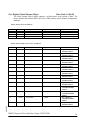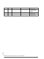
1
IVI-F47-DN1
DeviceNet
USER MANUAL
TABLE OF CONTENTS
General Information.............................................................................................3
Disable Support Method ......................................................................................4
Intelligent Support Method – With R/O ID System ...........................................5
DEVICENET COMMANDS ........................................................................................................................................... 7
Intelligent Support Method – With R/W ID System ........................................10
DEVICENET COMMANDS ......................................................................................................................................... 15
EDS Files -- Consumed and Produced Size.......................................................19
R/O ID SYSTEMS ..................................................................................................................................................... 19
R/W ID SYSTEMS .................................................................................................................................................... 19
DeviceNet Message Types and Class Services...................................................20
DEVICENET MESSAGE TYPES .................................................................................................................................. 20
DEVICENET CLASS SERVICES .................................................................................................................................. 20
DeviceNet Object Classes ...................................................................................20
06/2000
IDENTITY OBJECT
CLASS CODE: 01 (0X01) ................................................................................................... 21
CLASS CODE: 02 (0X02) ................................................................................................... 23
ROUTER OBJECT
CLASS CODE: 03 (0X03) ................................................................................................... 24
DEVICENET OBJECT
CLASS CODE: 04 (0X04) ................................................................................................... 26
ASSEMBLY OBJECT
CONNECTION OBJECT CLASS CODE: 05 (0X05).................................................................................................... 27
CLASS CODE: 64 (0X40) ............................................................ 30
USER DEFINED (SERIAL STREAM) OBJECT
USER DEFINED (IDENT-I SYSTEM V) OBJECT CLASS CODE: 65 (0X41) ............................................................ 41
PROPER CONFIGURATION OF THE SCANNER FOR READ/WRITE ................................................................................. 44
PROPER CONFIGURATION OF THE SCANNER FOR READ ONLY ................................................................................... 44
RS232 CONNECTIONS .............................................................................................................................................. 44
IDENT-I System V DeviceNet Bus Coupler, IVI-F47-DN1
2
General Information
The IVI-F47-DN1 (DN1) is a DeviceNet bus coupler for the Pepperl+Fuchs IDENT-I System V
inductive ID system and functions as a slave on the DeviceNet network. The unit supports
explicit messages and polled I/O messages of the predefined master/slave connection set, but
does not support the Explicit Unconnected Message Manager (UCMM). The DN1 performs all
protocol related steps (regarding the Pepperl+Fuchs IDENT-I System V identification system)
automatically allowing seamless operation.
The DN1 provides a DeviceNet interface with the IDENT-I System V inductive identification
system. It functions as a slave on the DeviceNet network and as a master to the ID system
controller. All RS232 connection parameters (baud rate, parity, etc.) can be programmed
through DeviceNet or adjusted using the potentiometers on the DN1.
The DN1 bus coupler offers full, intelligent support of serial IDENT-I System V ID system
controllers. The following control interfaces are supported:
q IRI-KHD2-4.RX
q IRI-KHA6-4.RX
q IVI-KHD2-4.RX
q IVI-KHD2-4.RX
This operating mode will be referred to as the Intelligent Support Method. It is the defaultoperating mode of the DN1, once power is applied1.
The DN1 supports all IDENT-I System V commands and performs many tasks automatically. The
DN1 automatically detects if an IRI (R/O) or IVI (R/W) style ID system controller is being used.
This allows seamless operation of the ID system and eliminates the need for the user to monitor
transmissions between the ID system controller and the DN1. Since the amount of data transmitted
and received across the DeviceNet (quantity Consumed and Produced) is different for R/O and R/W
systems, the appropriate EDS file must be used. The DN1 comes with a 3½” diskette that contains
2 EDS files, one EDS file (1.EDS) for R/W ID systems and one (2.EDS) for R/O ID systems. In the
Intelligent Support Method, two types of commands can be selected for each read/write head
connected to the ID system controller: Auto Repeat Commands and Manual Commands (see “User
Defined (IDENT-I System V) Object – Class Code 64”, see also “DeviceNet Commands on page 6
and page 12).
1
06/2000
The Disable Support Method is the alternate operating mode of the DN1. In this mode, the DN1 functions as a generic
DeviceNet-to-Serial bus coupler, enabling it to provide DeviceNet presents for any RS232 compatible peripheral device.
IDENT-I System V DeviceNet Bus Coupler, IVI-F47-DN1
3
The head is continuously read by the ID system in the Auto Mode. The read cycle continues even
after a valid read function has been completed. The data read function is stored in the DN1 buffer
until it is read through the DeviceNet.
The tag reader becomes passive in the Manual Mode, allowing the user to communicate with the ID
system controller through the serial class (class 64). This will be the standard mode of operation in
most cases because it allows the user precise control over the ID system.
Disable Support Method
06/2000
The DN1 provides a generic RS232 serial interface in the Disable Support Method, allowing serial
data to be transmitted and received from any RS232 compatible peripheral device. The RS232 serial
data is stored in an internal 64-byte receive FIFO buffer, allowing the unit to function
asynchronously to the DeviceNet network. Likewise, information transmitted to the serial device is
stored in a 64-byte serial FIFO buffer. The DN1 can be configured to operate at a number of
different baud rates and it supports flow control and parity.
IDENT-I System V DeviceNet Bus Coupler, IVI-F47-DN1
4
Intelligent Support Method – With R/O ID System
The Intelligent Support Method fully supports read only (R/O) and read/write (R/W) ID systems.
Use file 2.EDS for ID systems in the R/O mode. Employ the following command structure in
R/O mode ID systems:
Command Word
Apply the following format to send commands to the ID system:
[command,1][head#,1]
[command, 1]
is a one byte command that determines the type of read operation
to take place. The number “1” indicates the length in bytes needed
to specify the command.
[head, 1]
is a one byte parameter that determines which read head (1 to 4)
will be used for the operation.
DeviceNet Response
The poll response is formatted as follows:
[status,1][head #,1][ID command,1][ID status,2][response data,8]
[status, 1]
this 1 byte status indicator contains the following information:
bit #7:
0 indicates communication with a read only (R/O) ID
system
bit #6,5: fixed at 01
bit # 4: This bit has a value of 1 when the DeviceNet scanner
transmits new data from the ID system to the PLC. It has
a value of 0 when the DeviceNet scanner transmits data
previously received from the ID system.
bit#3,2,1,0:
0000 no heads in auto repeat mode
xxx1
head 1 is in auto repeat mode
xx1x head 2 is in auto repeat mode
x1xx head 3 is in auto repeat mode
06/2000
1xxx head 4 is in auto repeat mode
IDENT-I System V DeviceNet Bus Coupler, IVI-F47-DN1
5
[head #, 1]
This byte command indicates the head (1 to 4) used in the
operation therefore yielding [response data,8].
[ID command, 1] is the 1 byte command sent to the IDENT-I System V controller.
Note: This byte provides diagnostic help but does not contain any
user-data or operating-status information.
[ID status, 2]
is the 2 byte error response for the previous command. A list of the
error codes can be found in the IDENT-I System V Manual. In
addition, the DN1 generates a D1ASCII = (44hex 31hex) error
message if the RS 232 connection between the DN1 and the ID
system interface has been compromised.
If a code carrier is read successfully, the 2 byte [ID status,2]
command contains one byte representing the read head number
followed by <space> = 20hex.
If an error occurred, the 2 byte [ID status,2] command contains
two bytes representing the ID system error-code listed in the
IDENT-I System V manual.
06/2000
[response data, 8] is the data returned from the command. For example, this field
contains the data returned from the head if a read function was
requested. If no tag was read, no response data will be transmitted
and the appropriate error code will be issued via [ID status,2].
IDENT-I System V DeviceNet Bus Coupler, IVI-F47-DN1
6
DeviceNet Commands
The following lists commands for [command,1] which can be issued across the DeviceNet. The
DN1 performs all the necessary protocol related steps. The commands listed below operate on
one read head at a time. This means that the previous command is canceled when a new
command is issued to a different read head.
Manual Mode Commands:
[COMMAND,1]
OPERATION
Hex Values
00
01
02
03
04
End Running Command
Read Head
Read Head Auto – Command is executed until a code carrier is found
Read Code2
Read Code Auto3– Command is executed until a code carrier is found
0D
Dual-Sided Mode of ID Control Interface activated – This mode remains
active until the system is restarted (Hex Value = 11)
11
Restart ID Control Interface – Stops Dual-Sided Mode.
Auto-Repeat Mode Commands:
The Auto Repeat-Read Head Auto and Auto Repeat-Read Code Auto4 commands are executed
until canceled by using the End Auto Repeat command. This makes it possible to
simultaneously read code carriers using several read heads without having to reissue commands.
80
81
83
End Auto Repeat
Auto Repeat-Read Head Auto
Auto Repeat-Read Code Auto4
2
Command 03 is identical to command 01.
Command 04 is identical to command 02.
4
Command 83 is identical to command 81.
06/2000
3
IDENT-I System V DeviceNet Bus Coupler, IVI-F47-DN1
7
EXAMPLES
The following examples assume the use of an Allen-Bradley SLC and the mapping of a DN1
with a word offset of zero (0). The command string starts in Word 1 since DeviceNet uses Word
0. All words in the Output and Input Images are byte-swapped, allowing the customer to use the
examples exactly as they are listed below. The “mode28” tag code is 28162139ASCII. The
Output and Input Images are expressed in hexadecimal format. Word 1 of the Input Image
contains the new data bit, which can have changing values. This is indicated by x. The bit has a
value of 1 whenever the DN1 transmits data that has been read from the ID system. The DN1
transmits stored data resulting in a value of 0, during the next DeviceNet scan. Data read from
the tag is bold-faced in the tables below.
(1) READING AN (R/O) CODE CARRIER ONCE, USING HEAD 1 – TAG PRESENT
Output
(Command)
Word 1
01 01
Image
Word 2
Input Image (Response)
Word1
01 x0
Word2
31 52
Word3
32 20
Word4
31 38
Word5
31 36
Word6
33 31
Word7
00 39
Word5
Word6
Word7
(3) CONTINUOUSLY READING AN (R/O) CODE CARRIER USING HEAD 2 – TAG PRESENT
Output
Image
Input Image (Response)
(Command)
Word 1
Word 2
Word1 Word2 Word3 Word4 Word5
02 02
02 x0
31 52
32 20
31 38
31 36
Word6
33 31
Word7
00 39
Word6
Word7
Word6
33 31
Word7
00 39
(2) READING AN (R/O) CODE CARRIER ONCE, USING HEAD 3 – NO TAG PRESENT
Output
Image
Input Image (Response)
(Command)
Word 1
Word 2
Word1 Word2 Word3 Word4
03 01
03 x0
4D 52
0D 37
00 0A
(4) CONTINUOUSLY READING AN (R/O) CODE CARRIER USING HEAD 4 – NO TAG PRESENT
Output
Image
Input Image (Response)
(Command)
Word 1
Word 2
Word1 Word2 Word3 Word4 Word5
04 02
04 x0
4D 52
0D 37
00 0A
06/2000
(5) READING AN (R/O) CODE CARRIER WITH AUTO REPEAT USING HEAD 1 – TAG PRESENT
Output
Image
Input Image (Response)
(Command)
Word 1
Word 2
Word1 Word2 Word3 Word4 Word5
01 81
01 x1
31 52
32 20
31 38
31 36
IDENT-I System V DeviceNet Bus Coupler, IVI-F47-DN1
8
(6) READING AN (R/O) CODE CARRIER WITH AUTO REPEAT USING HEAD 3 –
Output
(Command)
Word 1
03 81
Image
Word 2
NO TAG PRESENT
Input Image (Response)
Word1
03 x4
Word2
4D 52
Word3
0D 37
Word4
00 0A
(7) SETTING THE DUAL-SIDED MODE
Output
Image
Input Image (Response)
(Command)
Word 1
Word 2
Word1 Word2 Word3 Word4
00 0D
00 00
Do not use
Word5
Word6
Word7
Word5
Word6
Word7
Since the ID system does not respond to this command, the DN1 assumes that the RS232
link was interrupted and attempts to reconnect. The value of Words 2-4 then changes and
should not be analyzed. Simply issue a read head command (e.g. 0101) and check the
response.
(8) RESETTING THE ID INTERFACE
Output
(Command)
Word 1
00 11
Image
Word 2
Input Image (Response)
Word1
00 00
Word2
Word3 Word4
Do not use
Word5
Word6
Word7
Since the ID system does not respond to this command, the DN1 assumes that the RS232
link was cut and attempts to reconnect. The value of Words 2-4 then changes and should
not be analyzed. Simply issue a read head command (e.g. 0101) and check the response.
(9) LOST RS232 COMMUNICATIONS
Output
Image
Input Image (Response)
(Command)
Word 1
Word 2
Word1 Word2 Word3
00 11
00 00
44 xx
00 31
Word4
Word5
Word6
Word7
06/2000
The DN1 response indicates that RS232 communications have been lost.
IDENT-I System V DeviceNet Bus Coupler, IVI-F47-DN1
9
Intelligent Support Method – With an R/W ID System
The Intelligent Support Method fully supports read only (R/O) and read/write (R/W) ID systems.
The 1.EDS file must be used with an ID system in the R/W mode. The poll command is in the
following format when using an R/W ID system. Please note that IMC series and IDC series data
carriers may have slightly different command formats in some cases.
COMMAND WORD
Use the following command structure for sending a command to an R/W ID system:
Reading the first 32 bytes on a data carrier or the code of a code carrier
[command,1][head#,1]
[command,1]is a one byte command specifying the type of operation to be
performed. A list of possible commands is given later.
[head#,1]
is the byte identifying which read/write head (1 to 4) will be used
for the operation
This command format applies to commands 01, 02,03,04, 81 and 83.
Reading a specific page of a data carrier
[command,1][head#,1][page #,w1]
[command,1] and [head#,1] as specified above
[page#,w1] is one word5 specifying which page is read from the data carrier.
One page contains 32 bytes of user data. The range of [page#,w1]
depends on the data carrier as listed below:
IDC
Not supported by 256-bits data carrier
IDC-…-1K
0000 to 0003 (4 pages)
IMC-…-64K
0000 to 00ff (256 pages)
IMC-…-256K
0000 to 03ff (1024 pages
This command format applies to commands 07, 08 and 87.
06/2000
5
Note that one byte commands and parameters are treated by DeviceNet as short integers, while one-word
commands are treated as an unsigned integer. This is important to note since DeviceNet reverts the order
of the bytes in short integers (“byte swap”), while bytes of unsigned integers are not reverted. This
difference is important for certain R/W commands.
IDENT-I System V DeviceNet Bus Coupler, IVI-F47-DN1
10
Writing to a specific page of a data carrier – Only IMC series data carriers support this
command
[command,1][head#,1][page #,w1][0000][user data,32]
[command,1] and [head#,1] as specified above
[page#,w1] is one word6 specifying which page is read or written to. One page
contains 32 bytes of user data. The range of [page#,w1] depends
on the data carriers listed below:
IDC
IDC-…-1K
IMC-…-64K
IMC-…-256K
Not supported by 256-bit data carrier
Not supported by 1K bit data carrier
0000 to 00ff (256 pages)
0000 to 03ff (1024 pages
[user data,32] determines 32 user bytes that are written to a specific page on the
data carrier.
This command format applies to commands 0B and 0C.
Read a particular address on the data carrier
[command,1][head#,1][start address,w1][#bytes,1]
[command,1] and [head#,1] as specified above
[start address,w1] is a one-word address specifying the data carrier address
where [#bytes,w1] bytes of user data are stored in or read from the
data carrier. The allowable range depends on the data carriers
listed below:
IDC
IDC-…-1K
IMC-…-64K
IMC-…-256K
[#bytes,1]
0000 to 001f
0000 to 007f
0000 to 1fff
0000 to 7fff
is a one byte data length specifying how many bytes of user data
are stored in or read from the data carrier, starting with address
06/2000
6
Note that one byte commands and parameters are treated by DeviceNet as short integers, while one-word
commands are treated as an unsigned integer. This is important to know since DeviceNet reverts the order
of the bytes in short integers (“byte swap”), while bytes of the unsigned integers are not reverted. This
difference is important for certain R/W commands.
IDENT-I System V DeviceNet Bus Coupler, IVI-F47-DN1
11
[start address,w1]. DeviceNet restricts this parameter to a
maximum of 20Hex bytes. If a larger number is used, only the first
20Hex bytes are written or read.
This command format applies to commands 05, 06 and 85.
Write bytes to a particular address on the data carrier
[command,1][head#,1][start address,w1][#bytes,1][user data,n]
[command,1] and [head#,1] as specified above
[start address,w1] is a one-word address specifying the data carrier address
where [#bytes,w1] bytes of user data are stored in or read from the
data carrier. The allowable range depends on the type of data
carrier used listed below:
IDC
IDC-…-1K
IMC-…-64K
IMC-…-256K
[#bytes,1]
0000 to 001f
0000 to 007f
0000 to 1fff
0000 to 7fff
is a one byte data length specifying the number of bytes to be
written to the data carrier starting with address [start address,w1].
DeviceNet restricts this parameter to a maximum of 20Hex bytes.
Only the first 20Hex bytes are written or read when using a larger
number.
[user data,n] specifies the user data that will be written to the data carrier
starting with address [start address,w1]. The [#bytes,1] command
specifies the number of user data bytes (n).
06/2000
This command format applies to commands 09and 0A.
IDENT-I System V DeviceNet Bus Coupler, IVI-F47-DN1
12
DeviceNet Response
The poll response uses the following command format:
[status,1][head #,1][ID command,1][ID status,2] [response data,m]
[status,1]
this byte contains the following information:
bit #7: 1 indicates communication with a read/write ID system
bit #6,5: fixed at 00
bit # 4: This bit has a value of 1 when the DeviceNet scanner
transmits new data from the ID system to the PLC. It has a
value of 0 when the DeviceNet scanner transmits data
previously received from the ID system.
bit#3,2,1,0:
0000 no heads in auto repeat mode
xxx1
head 1 is in auto repeat mode
xx1x head 2 is in auto repeat mode
x1xx head 3 is in auto repeat mode
1xxx head 4 is in auto repeat mode
[head#,1]
is the head (1 to 4) the operation was performed on.
[ID command,1]
is the command sent to the IDENT-I System V controller.
Note: This byte only provides diagnostic help. It does not contain
any user data or operations related status information.
06/2000
[ID status,2] is the 2-byte error response for the previous command. A list of the
error codes can be found in the IDENT-I System V Manual. In
addition, the DN1 generates the D1ASCII = (44hex 31hex) error
message when the RS 232 connection between the DN1 and the ID
system interface has been compromised. The 2-byte [ID status, 2]
response contains 30 hex (00ASCII) when a command is successfully
executed.
IDENT-I System V DeviceNet Bus Coupler, IVI-F47-DN1
13
06/2000
[response data,m] is the commands response data. This field contains the data
returned from the head when a read function is requested. For
example, when a read function is requested, this field contains the
head’s data response. If a tag is not read, the response data is not
transmitted and the appropriate error code is issued using [ID
status,2].
IDENT-I System V DeviceNet Bus Coupler, IVI-F47-DN1
14
DeviceNet Commands
The following commands can be issued through the DeviceNet. The DN1 performs all required
protocol related steps. The following commands operate on one read head at a time. For
example, the previous command is cancelled when a new command is issued to a different read
head.
Manual Mode Commands:
HEX VALUE
00
01
02
03
04
05
06
07
08
09
0A
0B
0C
0D
0F
11
OPERATION
End Running Command
Read Head (reads data carrier)
Read Head Auto – Command is executed until a data carrier has been read
Read Code (reads code carrier with IVI-Series ID control interface)
Read Code Auto – Command is executed until a code carrier has been read
Read Bytes
Read Bytes Auto – Command is executed until a data carrier has been read
Read Page
Read Page Auto – Command is executed until a data carrier has been read
Write Bytes
Write Bytes Auto– Command is executed until a data carrier has been
written
Write Page
Write Page Auto– Command is executed until a data carrier has been written
Double Sided Mode of ID Control Interface activated – this mode remains
active until a Restart (Hex Value = 11)
Set Data Carrier – Specifies the type of data carrier used (256bit = type 1,
1Kbit = type 4, or 64/256Kbit = type 3) – The data carrier type
remains active until changed by another Set Data Carrier command
or a Restart (Hex Value = 11)
Restart ID Control Interface – Stops Double-Sided Mode and reset to D4
data carriers.
Auto Repeat Mode Commands:
The Auto Repeat-Read Head Auto, Auto Repeat-Read Code Auto, Auto Repeat- Read Bytes
Auto and the Auto Repeat-Read Page Auto commands are executed until cancelled using the
End Auto Repeat command. This makes it possible to simultaneously read code carriers and
data carriers using multiple read heads without reissuing commands.
End Auto Repeat
Auto Repeat-Read Head Auto
Auto Repeat-Read Code Auto
Auto Repeat- Read Bytes Auto
Auto Repeat-Read Page Auto
06/2000
80
81
83
85
87
IDENT-I System V DeviceNet Bus Coupler, IVI-F47-DN1
15
EXAMPLES
The following examples assume the use of an Allen-Bradley PLC and the mapping of the DN1
with a word offset of zero. The command string starts with Word 1 since DeviceNet uses Word
0. All words in the Output and Input Images are byte-swapped (this is a feature of the A-B PLC)
allowing the user to simply type them in exactly as they are listed in the following examples.
Exceptions: [page#,w1] and [start address,w1] are unsigned integers. This should be noted
because DeviceNet does not restore the order of the bytes in unsigned integers (e.g. no “byte
swap”).
The code carrier’s code is B002139. Data written to or read from a data carrier is named D1, D2, D3
and so on. Output and input images are expressed as hexadecimal values. Word 1 of the input
image contains the new data bit and can therefore have changing values. This is indicated by x for
which the possible values are 9 (new data available) or 8 (no new data available). Data written to or
read from a tag is boldfaced in the examples below.
Note: ETX CHK is part of the ID system response and is only provided as a diagnostic tool. The
customer does not need to verify the checksum (CHK) which is done by the DN1.
(1) READING AN R/O CODE CARRIER ONCE USING HEAD 1 – TAG PRESENT
Output
Image
Input Image (Response)
(Command)
Word 1
Word 2
Word1 Word2 Word3 Word4
01 03
01 x0
30 69
42 30
30 30
Word5
31 32
Word6
39 33
Word7
Word5
Word6
Word7
(3) CONTINUOUSLY READING AN R/O CODE CARRIER USING HEAD 2 – TAG PRESENT
Output
Image
Input Image (Response)
(Command)
Word 1
Word 2
Word1 Word2 Word3 Word4 Word5
02 04
02 x0
30 69
42 30
30 30
31 32
Word6
39 33
Word7
Word6
Word7
(2) READING AN R/O CODE CARRIER ONCE USING HEAD 3 – NO TAG PRESENT
Output
Image
Input Image (Response)
(Command)
Word 1
Word 2
Word1 Word2 Word3 Word4
03 03
03 x0
30 69
CHK 33
00 ETX
ETX CHK
ETX CHK
(4) CONTINUOUSLY READING AN R/O CODE CARRIER USING HEAD 4 – HEAD NOT PRESENT
Image
Word 2
Input Image (Response)
Word1
02 x0
Word2
30 69
Word3
CHK 32
Word4
Word5
00 ETX
06/2000
Output
(Command)
Word 1
04 04
IDENT-I System V DeviceNet Bus Coupler, IVI-F47-DN1
16
(5) READING AN R/O CODE CARRIER WITH AUTO REPEAT USING HEAD 1 – TAG PRESENT
Output
Image
Input Image (Response)
(Command)
Word 1
Word 2
Word1 Word2 Word3 Word4 Word5
01 83
01 x1
30 69
42 30
30 30
31 32
Word6
39 33
(6) READING AN R/O CODE CARRIER WITH AUTO REPEAT USING HEAD 3 – NO TAG PRESENT
Output
Image
Input Image (Response)
(Command)
Word 1
Word 2
Word1 Word2 Word3 Word4 Word5 Word6
00 ETX
03 83
03 x4
30 69
CHK 33
Word7
ETX CHK
Word7
(7) READING THE FIRST 32DEC BYTES ON A DATA CARRIER USING HEAD 4 –HEAD NOT PRESENT
Output
(Command)
Word 1
04 01
Image
Word 2
Input Image (Response)
Word1
04 x0
Word2
30 61
Word3
CHK 32
Word4
Word5
Word6
Word7
(8) READING THE FIRST 32DEC BYTES ON A DATA CARRIER USING HEAD 3 – TAG PRESENT
Output
Image
Input Image (Response)
(Command)
Word 1
Word 2
Word1 Word2 Word3 Word4 Word5
03 01
03 x0
30 61
D3 D2
D5 D4
D1 30
Word6
D7 D6
Word7
Cont.
(9) AUTO REPEAT READING THE FIRST 32DEC BYTES ON DATA CARRIER USING HEAD 2 – TAG PRESENT
Output
Image
Input Image (Response)
(Command)
Word 1
Word 2
Word1 Word2 Word3 Word4 Word5 Word6
02 81
02 x2
30 61
D3 D2
D5 D4
D7 D6
D1 30
Word7
Cont.
00 ETX
(10) READ 5HEX BYTES AT DATA CARRIER ADDRESS 0BHEX USING HEAD 1 – TAG PRESENT
Output Image (Command)
Input Image (Response)
Word 1 Word 2 Word3 Word4
Word1 Word2 Word3 Word4
01 05
00 0B 00 05
01 x0
30 77
D3 D2
D1 30
Word5
D5 D4
Word6
ETX CHK
(11) AUTO REPEAT READ 0AHEX BYTES AT DATA CARRIER ADDRESS 13HEX USING HEAD 3 – TAG PRESENT
Output Image (Command)
Input Image (Response)
Word 1 Word 2 Word3 Word4
Word1 Word2 Word3 Word4 Word5 Word6
03 81
00 13
00 0A
03 x4
30 61
D3 D2
D5 D4
Cont.
D1 30
Word4
D3 D2
Word5
D5 D4
Word6
Cont.
06/2000
(12) READ 2ND DATA PAGE USING HEAD 3 – TAG PRESENT
Output Image (Command)
Input Image (Response)
Word 1 Word 2 Word3 Word4
Word1 Word2 Word3
03 07
00 02
03 x0
30 6C
D1 30
IDENT-I System V DeviceNet Bus Coupler, IVI-F47-DN1
17
(13) WRITING 2HEX BYTES AT DATA CARRIER ADDRESS 09HEX USING HEAD 2 – TAG PRESENT
Output Image (Command)
Input Image (Response)
Word 1 Word 2 Word3 Word4
Word1 Word2 Word3 Word4
02 09
00 09
02 x0
30 6B CHK 30 00 ETX
D1 02
xx D2
Word5
Word6
(14) SWITCH INTERFACE TO USE IMC-SERIES DATA CARRIER (TYPE 3) – THE FOLLOWING EXAMPLE ASSUMES
THE USE OF IMC SERIES DATA CARRIERS
Output Image (Command)
Input Image (Response)
Word 1 Word 2 Word3 Word4
Word1 Word2 Word3 Word4 Word5 Word6
ETX CHK
03 0F
00 x0
64 64
(15) READ 3CTH DATA PAGE USING HEAD 3 – TAG PRESENT (IMC-SERIES DATA CARRIER ONLY)
Output Image (Command)
Input Image (Response)
Word 1 Word 2 Word3 Word4
Word1 Word2 Word3 Word4 Word5
03 07
00 3C
03 x0
30 6C
D1 30
D3 D2
D5 D4
Word6
Cont.
(16) WRITING 2HEX BYTES AT DATA CARRIER ADDRESS 09HEX USING HEAD 3 – TAG PRESENT (IMC-SERIES DATA
CARRIER ONLY)
Output Image (Command)
Input Image (Response)
Word 1 Word 2 Word3 Word4
Word1 Word2 Word3 Word4 Word5 Word6
0309
0009
03 x0
30 6B CHK 30 00 ETX
D102
xxD2
(17) WRITING 3HEX BYTES AT DATA CARRIER ADDRESS 100HEX USING HEAD 3 – TAG PRESENT (IMC-SERIES DATA
CARRIER ONLY)
Output Image (Command)
Input Image (Response)
Word 1 Word 2 Word3 Word4
Word1 Word2 Word3 Word4 Word5 Word6
03 x0
30 6B CHK 30 00 ETX
0309
0100
D3D2
D103
(18) WRITING 3RD PAGE TO DATA CARRIER USING HEAD 4 – TAG PRESENT (IMC-SERIES DATA CARRIER ONLY)
Output Image (Command)
Input Image (Response)
Word 1 Word 2 Word3 Word4
Word1 Word2 Word3 Word4 Word5 Word6
32Bytes
03 0B
00 03
00 00
03 x0
30 6D CHK 30 00 ETX
Word4
Word5
Word6
Word7
06/2000
(19) SETTING THE DUAL-SIDED MODE
Output
Image
Input Image (Response)
(Command)
Word 1
Word 2
Word1 Word2 Word3
ETX CHK
00 0d
00 x0
62 63
IDENT-I System V DeviceNet Bus Coupler, IVI-F47-DN1
18
RESETTING THE ID INTERFACE
Output
(Command)
Word 1
0011
Image
Word 2
LOST RS232 COMMUNICATIONS
Output
Image
(Command)
Word 1
Word 2
0011
Input Image (Response)
Word1
00 x0
Word2
4F 4F
Word3
Word4
Word5
Word6
Word7
Word4
Word5
Word6
Word7
ETX CHK
Input Image (Response)
Word1
00 00
Word2
44 xx
Word3
00 31
The D1(ASCII) = 44hex 31hex response indicates that RS232 communication have been
lost.
EDS Files -- Consumed and Produced Size
R/O (Read Only) ID systems
Use the 2.EDS file found on the accompanying diskette, if connecting the DN1 to an
R/O ID system. This results in the following Produced and Consumed Size values:
Read Only
Produced Size (Rx)
13
Consumed Size (Tx)
2
R/W (Read/Write) ID systems
Use file 1.EDS found on the diskette if connecting the DN1 to an R/W ID system. This
results in the following Produced and Consumed Size values:
Produced Size (Rx)
37
Consumed Size (Tx)
38
06/2000
Read/Write
IDENT-I System V DeviceNet Bus Coupler, IVI-F47-DN1
19
DeviceNet Message Types and Class Services
DeviceNet Message Types
The IVI-F47-DN1 supports the following message formats as a Group 2 slave:
CAN IDENTIFIER
10xxxxxx111
10xxxxxx110
10xxxxxx101
10xxxxxx100
GROUP 2 Message Type
Duplicate MACID Check Message
Unconnected Explicit Request Message
Master I/O Poll Command Message
Master Explicit Request Message
xxxxxx = Node Address
DeviceNet Class Services
The IVI-F47-DN1 supports the following class services and instance services as a Group
2 slave:
SERVICE CODE
05 (0x05)
14 (0x0E)
16 (0x10)
75 (0x4B)
76 (0x4C)
SERVICE NAME
Reset
Get Attribute Single
Set Attribute Single
Allocate Group 2 Identifier Set
Release Group 2 Identifier Set
DeviceNet Object Classes
The IVI-F47-DN1 supports the following DeviceNet object classes:
OBJECT TYPE
Identity
Router
DeviceNet
Assembly
Connection
User defined serial interface
Parameter (IDENT-I System V support)
06/2000
CLASS CODE
01 (0x01)
02 (0x02)
03 (0x03)
04 (0x04)
05 (0x05)
64 (0x40)
65 (0x41)
IDENT-I System V DeviceNet Bus Coupler, IVI-F47-DN1
20
Identity Object
Class Code: 01 (0x01)
The Identity Object is necessary for all devices and provides device identification and
general information.
IDENTITY OBJECT CLASS ATTRIBUTES
Attribute
1
2
6
7
Access
Get
Get
Get
Get
Name
Revision
Max Object Instance
Max Class Identifier
Max Instance Attribute
Type
Value
UINT
UINT
UINT
UINT
1
1
7
7
Type
UINT
UINT
UINT
STRUCT OF
USINT
USINT
UINT
Value
57
0 = Generic
1
IDENTITY OBJECT, INSTANCE 1 ATTRIBUTES
Attribute
1
2
3
4
Access
Get
Get
Get
Get
5
Get
Name
Vendor
Product Type
Product Code
Revision
Major Revision
Minor Revision
Device Status
6
Get
Serial Number
UINT
7
Get
Product Name
Length
Name
STRUCT OF
USINT
STRING [6]
1
59hex = 89dec
(1) Refer to “Possible
Attribute Values”
(2) Refer to “Possible
Attribute Values”
6
IVI-F47-DN1
COMMON SERVICES
Class
No
Yes
Instance
Yes
Yes
Service Name
Reset
Get_Attribute_Single
06/2000
Service Code
05 (0x05)
14 (0x0E)
IDENT-I System V DeviceNet Bus Coupler, IVI-F47-DN1
21
POSSIBLE ATTRIBUTE VALUES
(1) Device Status
bit 0
bit 1
bit 2
bit 3
bit 4-7
bit 8
bit 9
bit 10
bit 11
bit 12-15
owned
0=not owned
1=owned (allocated)
reserved
0
configured
0
reserved
0
vendor specific
0
minor cfg fault
0=no fault
1=minor fault
minor dev.fault0=no fault
1=minor device fault
major cfg.fault
0=no fault
1=major cfg. fault
major dev.fault
0=no fault
1=major device fault
reserved
0
(2) Serial Number
06/2000
Unique Serial Number
IDENT-I System V DeviceNet Bus Coupler, IVI-F47-DN1
22
Router Object
Class Code: 02 (0x02)
The Message Router Object provides a messaging interface which a client can use to
address a service to any object class or instance within the actual device.
ROUTER OBJECT CLASS ATTRIBUTES
Attribute
1
6
7
Access
Get
Get
Get
Name
Revision
Max Class Identifier
Max Instance Attribute
Type
UINT
UINT
UINT
Value
1
7
2
Type
UINT
Value
2
ROUTER OBJECT, INSTANCE 1 ATTRIBUTES
Attribute
2
Access
Get
Name
Number of Connections
COMMON SERVICES
Class
Yes
Instance
Yes
Service Name
Get_Attribute_Single
06/2000
Service Code
14 (0x0E)
IDENT-I System V DeviceNet Bus Coupler, IVI-F47-DN1
23
DeviceNet Object
Class Code: 03 (0x03)
DEVICENET OBJECT CLASS ATTRIBUTES
Attribute
1
Access
Get
Name
Revision
Type
UINT
Value
2
Type
USINT
USINT
BOOL
USINT
STRUCT of
BYTE
USINT
Value
(1)
(2)
(3)
(4)
(5)
ROUTER OBJECT, INSTANCE 1 ATTRIBUTES
Attribute
1
2
3
4
5
Access
Get/Set
Get/Set
Get/Set
Get/Set
Get/Spc
Name
MACID
Baud Rate
Bus Off Interrupt
Bus Off Counter
Allocation Information
Choice Byte
Master Node Addr.
COMMON SERVICES
Service Code
14 (0x0E)
16 (0x10)
75 (0x4B)
76 (0x4C)
Class
Yes
No
No
No
Instance
Yes
Yes
Yes
Yes
Service Name
Get_Attribute_Single
Set_Attribute_Single
Allocate Master/Slave
Release Master/Slave
POSSIBLE ATTRIBUTE VALUES
1) MACID
Only adjustable when the MacID switches are set to a value greater than 63. The value
returned is the switch value if it is less than 64 or the last value entered.
(2) Baud Rate
06/2000
Only adjustable when the baud rate switch is set to a value greater than two. The value
returned will be the switch value if less than four or the last value entered.
Switch/Value
Speed
0
125 kbits
1
250 kbits
2
500 kbits
3
Software adjustable
IDENT-I System V DeviceNet Bus Coupler, IVI-F47-DN1
24
(3) Bus Off Interrupt
Bus Off Interrupt (BOI) determines the next action when a Bus Off state is encountered.
The following values are supported:
Bus Off Interrupt (BOI)
Action
0
Hold chip in OFF state (default)
1
Reset CAN chip if possible
(4) Bus Off Counter
Bus Off Counter will be forced to zero whenever set, regardless of the data.
(5) Allocation_byte
set to 1 to allocate
set to 1 to allocate
(not supported)
reserved (always 0)
06/2000
bit 0 explicit
bit 1 polled
bit 2 strobed
bit 3-7
IDENT-I System V DeviceNet Bus Coupler, IVI-F47-DN1
25
Assembly Object
Class Code: 04 (0x04)
The Assembly Object combines attributes of multiple objects allowing object data to be
transmitted or received through a single connection.
ASSEMBLY OBJECT CLASS ATTRIBUTES
Attribute
1
2
Access
Get
Get
Name
Revision
Max Class ID
Type
UINT
UINT
Value
1
2
Type
see notes
Value
(1) Refer to “Possible
Attribute Values”
Type
see notes
Value
(2) Refer to “Possible
Attribute Values”
ASSEMBLY OBJECT, INSTANCE 1 ATTRIBUTES
Attribute
3
Access
Get
Name
Data Stream (Input)
ASSEMBLY OBJECT, INSTANCE 2 ATTRIBUTES
Attribute
3
Access
Get/Set
Name
Data Stream (Output)
COMMON SERVICES
Service Code
14 (0x0E)
16 (0x10)
Class
Yes
Yes
Instance
Yes
Yes
Service Name
Get_Attribute_Single
Set_Attribute_Single
06/2000
Note: See the DeviceNet information above for an explanation of the poll command and
response specifications.
IDENT-I System V DeviceNet Bus Coupler, IVI-F47-DN1
26
Connection Object
Class Code: 05 (0x05)
The Connection Object manages the characteristics of each communication link. The
IVI-F47-DN1 supports one explicit message connection and a poll message connection
as a Group 2-only Slave Device.
CONNECTION OBJECT CLASS ATTRIBUTES
Attribute
1
Access
Get
Name
Revision
Type
UINT
Value
1
CONNECTION OBJECT, INSTANCE 1 ATTRIBUTES (EXPLICIT MESSAGE)
Access
Get
Name
State
Type
USINT
2
3
4
Get
Get
Get
Instance Type
Transport Class Trigger
Production Connection
USINT
USINT
UINT
5
Get
Consumed Connection
UINT
6
7
8
9
12
Get
Get
Get
Get/Set
Get/Set
Initial Comm. Char.
Production Size
Consumed Size
Expected Packet Rate
Timeout Action
USINT
UINT
UINT
UINT
USINT
13
14
Get
Get
Prod. Path Length
Production Path
USINT
15
16
Get
Get
Cons. Path Length
Consumed Path
USINT
17
Get
Production Inhibit
UINT
Value
(1) Refer to “Possible
Attribute Values”
0 = Explicit Message
0x83
(2) Refer to “Possible
Attribute Values”
(2) Refer to “Possible
Attribute Values”
0x21
67
71
Default 2500 msec
(3) Refer to “Possible
Attribute Values”
0
(4) (null) Refer to
“Possible Attribute
Values”
0
(4) (null) Refer to
“Possible Attribute
Values”
0
06/2000
Attribute
1
IDENT-I System V DeviceNet Bus Coupler, IVI-F47-DN1
27
CONNECTION OBJECT, INSTANCE 2 ATTRIBUTES (POLL CONNECTION)
Attribute
1
Access
Get
Name
State
Type
USINT
2
3
4
Get
Get
Get
Instance Type
Transport Class Trigger
Production Connection
USINT
USINT
UINT
5
Get
Consumed Connection
UINT
6
7
8
9
12
Get
Get
Get
Get/Set
Get/Set
Initial Comm. Char.
Production Size
Consumed Size
Expected Packet Rate
Timeout Action
USINT
UINT
UINT
UINT
USINT
13
14
Get
Get
Prod. Path Length
Production Path
Log. Seg., Class
Class Number
Log.Seg., Instance
Instance Number
Log.Seg., Attribute
Attribute Number
Cons. Path Length
Production Path
Log. Seg., Class
Class Number
Log.Seg., Instance
Instance Number
Log.Seg., Attribute
Attribute Number
Production Inhibit
USINT
STRUCT of
USINT
USINT
USINT
USINT
USINT
USINT
USINT
STRUCT of
USINT
USINT
USINT
USINT
USINT
USINT
USINT
15
16
Get
Get
17
Get
Value
(1) Refer to “Possible
Attribute Values”
1 = I/O Message
0x82
(2) Refer to “Possible
Attribute Values”
(2) Refer to “Possible
Attribute Values”
0x1
See Stream Object
See Stream Object
Default 2500 msec
(3) Refer to “Possible
Attribute Values”
6
0x20
0x04
0x24
0x01
0x30
0x03
6
0x20
0x04
0x24
0x02
0x30
0x03
0
COMMON SERVICES
Class
Yes
Yes
No
Instance
Yes
Yes
Yes
Service Name
Reset
Get_Attribute_Single
Set_Attribute_Single
06/2000
Service Code
05 (0x05)
14 (0x0E)
16 (0x10)
IDENT-I System V DeviceNet Bus Coupler, IVI-F47-DN1
28
POSSIBLE ATTRIBUTE VALUES
(1) States
Connection State
0=
nonexistent
1=
configuring
3=
established
4=
timed out
(2) Production Connection/Consumed Connection
Connection ID:
Connection 1 Produced Connection ID: 10xxxxxx011
Connection 1 Consumed Connection ID: 10xxxxxx100
Connection 2 Produced Connection ID: 01111xxxxxx
Connection 2 Consumed Connection ID: 10xxxxxx101
xxxxxx = Node Address.
(3) Timeout Action
Watch Dog TimeOut Activity:
0=
Timeout
(Explicit Messaging default)
1=
Auto Delete
2=
Auto Reset
(I/O Message default)
(4) Production Path/Consumed Path
06/2000
A 0 length (null) packet is received if data is not available during the poll response.
IDENT-I System V DeviceNet Bus Coupler, IVI-F47-DN1
29
User Defined (Serial Stream) Object
Class Code: 64 (0x40)
The Serial Stream Object model supports a bi-directional serial stream of data. The
object includes the transmit FIFO, the receive FIFO and the serial channel configuration
attributes.
SERIAL STREAM CLASS ATTRIBUTES
Attribute
1
2
6
7
Access
Get
Get
Get
Get
Name
Revision
Max Object Instance
Max Class Identifier
Max Instance Attribute
Type
UINT
UINT
UINT
UINT
Value
2
1
7
18
Value
(1) Refer to “Possible
Attribute Values”
(1) Refer to “Possible
Attribute Values”
(2) Refer to “Possible
Attribute Values”
(3) Refer to “Possible
Attribute Values”
(4) Refer to “Possible
Attribute Values”
(5) Refer to “Possible
Attribute Values”
(6) Refer to “Possible
Attribute Values”
(7) Refer to “Possible
Attribute Values”
(8) Refer to “Possible
Attribute Values”
(9) Refer to “Possible
Attribute Values”
(10) * Refer to
“Possible Attribute
Values”
(11) * Refer to
“Possible Attribute
Values”
(12) * Refer to
“Possible Attribute
Values”
(13) Refer to “Possible
Attribute Values”
SERIAL STREAM OBJECT, INSTANCE 1 ATTRIBUTES
Access
Get
Name
Receive Data
Type
See Notes
4
Set
Transmit Data
See Notes
5
Get/Set
Status
USINT
6
Get/Set
Baud Rate
USINT
7
Get/Set
Parity
USINT
8
Get
Data Size
USINT
9
Get
Stop Bits
USINT
10
Get/Set
Flow Control
USINT
11
Get/Set
Receive Count
USINT
12
Get/Set
Transmit Count
USINT
13
Get/Set
Maximum Receive Size
USINT
14
Get/Set
Data Format
USINT
15
Get/Set
Block Mode
USINT
16
Get/Set
Receive Delimiter
USINT
06/2000
Attribute
3
IDENT-I System V DeviceNet Bus Coupler, IVI-F47-DN1
30
Get/Set
Pad Char
CHAR
18
Get/Set
Maximum Transmit size
USINT
19
Get/Set
Idle String
SHORT_STRING
20
Get/Set
Fault String
SHORT_STRING
(14) Refer to “Possible
Attribute Values”
(15) * Refer to
“Possible Attribute
Values”
(16) Refer to “Possible
Attribute Values”
(17) Refer to “Possible
Attribute Values”
06/2000
17
IDENT-I System V DeviceNet Bus Coupler, IVI-F47-DN1
31
COMMON SERVICES
Service Code
5 (0x05)
14 (0x0E)
16 (0x10)
Class
No
Yes
No
Instance
Yes
Yes
Yes
Service Name
Reset
Get_Attribute_Single
Set_Attribute_Single
* Items marked with an asterisk may affect the produced or consumed size of the poll
connection.
POSSIBLE ATTRIBUTE VALUES
(1) Receive Data/Transmit Data
The Received Data (Attribute 3) and Transmitted Data (Attribute 4) are either an array of
bytes or a SHORT_STRING defined by DeviceNet consisting of a length byte followed by
the specific number of valid data bytes. The format is determined by the Data Format
parameter. Note that reading the Transmit Data will return a single byte, indicating the last
byte of the FIFO.
Data is not transmitted when a packet with zero data bytes is received. A response packet is
not generated if there is insufficient room for the packet in the transmit FIFO.
The response packet will either be an array of bytes or a SHORT_STRING when the data is
read. A NULL packet or an array with a zero length byte is received if data is not available.
(2) Status
The Status information (Attribute 5) indicates whether data transfer errors have occurred. It
is bit mapped as follows:
bit 0
bit 1
bit 2
bit 3
bit 4
bit 5
bit 6
bit 7
*
*
*
*
Transmit channel blocked
Transmit FIFO empty
Receive Parity error
Receive FIFO empty
Receive Overflow
Framing Error
Transmit FIFO Overflow
State of CTS signal (1 = Asserted)
06/2000
* Writing any value into the status field will clear the error bits.
IDENT-I System V DeviceNet Bus Coupler, IVI-F47-DN1
32
Possible Attribute Values, cont.
(3) Baud Rate
The baud rate (Attribute 6) can be adjusted using the RS232 baud rate switch or the
software. The switch must be in the ‘PRG’ position to allow software adjustments.
Baud Rate
0
1
2
3
4
5
6
Interpretation
9600 baud
4800 baud
2400 baud
1200 baud
600 baud
300 baud
19.2 Kbaud
(4) Parity
The parity (Attribute 7) can be adjusted using the software. Note: setting the parity to zero
changes the data length size to eight. Setting the parity to a value other than zero changes the
data length size to seven.
Parity
0
1
2
3
4
5
6
Interpretation
No parity
Even parity
Odd parity
N/A
N/A
Force to 1
Force to 0
(5) Data Size
The data size (Attribute 8) is read-only. The IVI-F47-DN1 serial channel always processes
eight information bits. Eight data bits are transmitted/received if parity is set to zero (no
parity). If the parity is set to a value other than zero, then only seven data bits are transmitted
and the 8th bit is used as the parity bit. The data size field is read-only.
(6) Stop Bits
06/2000
The Stop bits (Attribute 9) is read-only. The IVI-F47-DN1 serial channel always operates
with one stop bit. The Stop Bits field is read-only and fixed at one stop bit.
IDENT-I System V DeviceNet Bus Coupler, IVI-F47-DN1
33
Possible Attribute Values, cont.
(7) Flow Control
Flow control (Attribute 10) can be set by software.
Flow Control
0
1
2
3
4
Interpretation
No flow control
X-ON/X-OFF flow control
Hardware flow control
DO NOT USE
CTS Detect Mode
If the flow control is set to one, the ASCII standard X-OFF (CTRL S) character will force the
transmit function to block. Characters will be stored in the transmit-FIFO’s buffer until the
transmitter is reactivated using the X-ON (CTRL Q) character. Note that the CTRL-S and
CTRL-Q characters are stripped from the incoming data stream making this protocol
unsuitable for binary data transmission.
The IVI-F47-DN1 will transmit an X-OFF character when the receive-FIFO is full. An XON character is transmitted when the number of characters in the receive-FIFO drops below
50%.
The IVI-F47-DN1 uses the RTS and CTS hardware signals to control flow if the flow
control is set to 2. The unit will only transmit if the CTS signal (Pin 8) is asserted (+
voltage).
The RTS (pin 7) signal is asserted (+ voltage) if the receive-FIFO has room to receive
characters.
The CTS Detect mode allows the IVI-F47-DN1 to detect the presence of the CTS signal. The
IVI-F47-DN1 is free to communicate to the RS232 device when the signal is asserted. When
unasserted, the IVI-F47-DN1 will purge the receive-FIFO as if the RS232 device were
offline. The CTS Detect mode can be used to determine if the RS232 device is connected to
the IVI-F47-DN1.
(8) Receive Count
The Receive Count (Attribute 11) indicates the number of characters currently available in
the receive-FIFO. Writing any value will purge the receive-FIFO.
(9) Transmit Count
06/2000
The Transmit Count (Attribute 12) indicates the number of characters currently in the
transmit-FIFO. Writing any value will purge the transmit-FIFO.
IDENT-I System V DeviceNet Bus Coupler, IVI-F47-DN1
34
Possible Attribute Values, cont.
(10) Maximum Receive
The Maximum Receive Size (Attribute 13) indicates the maximum number of data bytes
returned when the receive-FIFO is read (attribute 3) by either using EXPLICIT messages or
through the POLL connection. Setting this attribute will automatically reset the Produced
Connection size to:
Connection size = Max Rcv Size (Maximum size is 64)
+
1 (if String Format enabled)
+
1 (if Receive Seq. Num. enabled)
The maximum connection size is 66 bytes.
(11) Data Format
The Data Format (Attribute 14) control byte determines the type of
data strings transmitted through the DeviceNet channel, which can
either be an array of bytes or a SHORT_STRING defined by
DeviceNet, consisting of a length byte followed by the specific
number of valid data bytes. Note that the data length byte does not
appear on the serial channel. The Data Format control byte also
determines whether the parity information is retained in the receiveFIFO. If the bit is cleared then the parity information is retained.
When it is set, the parity information is overwritten with zero
ensuring that only valid ASCII characters (0-7FH) appear in the
FIFO.
Bit 7
X
Bit 6
X
Bit 5
X
Bit 4
X
Bit 3
PADR
Bit 2
PL/R
Bit 1
Strip
Parity
Bit 0
String
Format
String Format
Interpretation
0
Process FIFO packets as SHORT_STRING variables
1
Process FIFO packets as an array of bytes. The array length defines
the number of valid bytes.
Strip Parity
0
1
Interpretation
Left-justify received character string if PADR set
Right-justify received character string if PADR set
06/2000
PL/R
0
1
Interpretation
Retain Parity information in receive FIFO
Set MSB of receive FIFO data to 0
IDENT-I System V DeviceNet Bus Coupler, IVI-F47-DN1
35
PADR
Interpretation
Possible Attribute Values, cont.
0
1
Do not attempt to PAD received characters
Pad received characters strings with PADCHAR
If the PADR bit is set in block mode with the Strip Delimiter bit, clear the pad characters
will be inserted between the last valid data bit and the end of the packet.
(12) Block Mode
The Block Mode (Attribute 15) control byte determines whether or not the unit prepares the
RS232 serial stream, whether block sequence numbers are pre-pended to the DeviceNet
packets and whether received data is retransmitted on subsequent POLL requests. The
control byte has the following format:
Bit 7
X
Bit 6
Sync
Bit 5
ReSend
Bit 4
Enable Xmit
Seq. Number
Bit 3
Enable Rcv.
Seq.Number
Bit 2
Delimiter
Enable
Bit 1
Strip
Delimiter
Bit 0
Pre/Post
Delimiter
Pre/Post Delimiter
0
1
Interpretation
Delimiter (if enabled) occurs at the end of the packet.
Delimiter (if enabled) occurs at the start of the packet. The
packet length is limited to the <Max Receive Size> length.
Excess characters are discarded.
Strip Delimiter
0
1
Interpretation
The delimiter character appears in the response packet.
The delimiter character is removed from the response packet.
Delimiter Enable
0
1
Interpretation
Disable the delimit character function
Enable the delimit character function
Enable Rcv.Seq.Num
Interpretation
0
Disable the receive sequence number
1
Each response packet will have a sequential number prepended to allow the scanner to detect new response data.
06/2000
Enable Xmt.Seq.Num
Interpretation
0
Disable the transmit sequence number
IDENT-I System V DeviceNet Bus Coupler, IVI-F47-DN1
36
Possible Attribute Values, cont.
1
The first byte of the poll request must contain a number that
is different from the one in the last request to allow for an
update of the scanner data field without generating erroneous
data on the RS232 channel.
Resend
0
1
Interpretation
Valid data is only transmitted once.
Valid data is present during subsequent poll requests until a
new string of valid data is received over the RS232 serial
channel.
Sync
0
1
Interpretation
Do not apply synchronous “hand-shake” protocol
Apply synchronous “hand-shake” protocol
The first byte contains a sequence number and the second byte
contains the string length information when using <string>
formatting and sequence numbers in the configuration of a IVI-F47DN1.
The receive-packet size may affect data responses if the delimiter
function is enabled. If the post delimiter field is zero, the IVI-F47DN1 will not transmit response data until the delimiter character is
detected or until <receive data size> bytes are available. If the
receive-data size setting is less than the number of available
characters, then the initial poll-response will contain the first
<receive data size> bytes and the second poll response will receive
the remaining characters up to the delimiter.
The IVI-F47-DN1 will not transmit response-data when the post
delimiter field setting is one, until a delimiter is detected and:
06/2000
1) more than <receive data size> bytes have been received, or
2) another delimiter is detected
IDENT-I System V DeviceNet Bus Coupler, IVI-F47-DN1
37
Possible Attribute Values, cont.
Characters, which exceed the receive data size are discarded.
When the Resend bit is set, the device will retransmit data on subsequent poll requests until
another valid data packet has been received.
The Sync bit enables the synchronous handshake protocol, which provides further control
over the sequence numbers during poll request/response transactions, to allow the master to
determine whether or not…
a) …the previous poll request packet has been accepted.
b) …the current poll response represents a new data string.
The Xmt.Seq.Num and Rcv.Seq.Num bits will change to one when the Sync bit is set to
one.
The Xmt.Seq.Num is received in the poll request and interpreted as two, four-bit numbers:
Bit Numbers 4-7
ReceiveAcknowledgeNumber
Bit Numbers 0-3
TransmitRequestNumber
The TransmitRequestNumber functions in the same way as the Xmt.Seq.Num described
above. The IVI-F47-DN1 ignores data in the poll request until the TransmitRequestNumber
changes from the previously received TransmitRequestNumber. The current data (if any)
will be ignored when a value of 0 is received. Zero acts as a ‘reset’ function for the
TransmitRequestNumber.
The ReceiveAcknowledgeNumber is compared to the ReceiveRequestNumber (see below).
If it equals the ReceiveRequestNumber, it releases the current receive data buffer allowing
the IVI-F47-DN1 to send new information. A value of zero will reset the
ReceiveRequestNumber.
The Rcv.Seq.Num is transmitted in the poll response and interpreted as two, four-bit
numbers:
Bit Numbers 4-7
ReceiveRequestNumber
Bit Numbers 0-3
TransmitAcknowledgeNumber
06/2000
The TransmitAcknowledgeNumber will be the same value as the most recently processed
TransmitRequestNumber. The TransmitRequestNumber is compared to the last
TransmitAcknowledgeNumber when a poll request packet is received. The data contained in
the poll request is transmitted if the TransmitRequestNumber differs from the
TransmitAcknowledgeNumberent (see above).
IDENT-I System V DeviceNet Bus Coupler, IVI-F47-DN1
38
Possible Attribute Values, cont.
The TransmitRequestNumber is then transferred to the TransmitAcknowledgeNumber to
notify the master that the transaction has been processed.
The IVI-F47-DN1 notifies the master that the poll response contains new data with the
ReceiveRequestNumber. The IVI-F47-DN1 will increment the most previous
ReceiveAcknowledgeNumber (see above) and return it using the poll response if new data is
available. Note that the IVI-F47-DN1 will generate numbers from 1-15 using zero as the
reset value.
The Sync mode is typically used with a ‘scanner’ that generates continuous poll requests.
The Xmt.Seq.Num should be set to a value of 00 during the first poll request (possibly no
valid data), thereby resetting the receive-handshaking logic on the IVI-F47-DN1. The poll
response will have the Rcv.Seq.Num set to ?0 when there is no available receive data. If data
is available, the IVI-F47-DN1 will generate a poll response with the Rcv.Seq.Num set to ?1
with the associated data contained in the response packet. Further data will be stored in the
buffers until the scanner generates a poll request with a Xmt.Seq.Num having a value of ?1.
This acknowledges the receipt and processing of the previous poll. The scanner should
increment the ReceiveAcknowledgeNumber after processing each poll response, wrapping
from 15-1.
During transmission, the scanner application code may build the request message in
memory and then increment the TransmitRequestNumber (1-15). This allows the
background scanner function to send ‘partially complete’ poll requests without generating
extraneous RS232 transmissions. When the scanner application code detects that the
TransmitAcknowledgeNumber is received as part of the poll response and matches the
previous TransmitRequestNumber, it will indicate that the scanner has successfully
transmitted the previous poll data and the application can proceed to generate new RS232
transmit data.
(13) Receive Delimiter
The delimiter character (Attribute 16) determines the start or end of packet character for the
RS232 channel. It is only effective if the delimiter enable bit in the block control byte is set.
(14) Pad Char
06/2000
The Pad Char (Attribute 17) is used to pad string formatted receive data. It is typically set to
ASCII <space> (020H) or an ASCII <null> (0).
IDENT-I System V DeviceNet Bus Coupler, IVI-F47-DN1
39
Possible Attribute Values, cont.
(15) Maximum Transmit Size
The Maximum Transmit Size (Attribute 18) indicates the maximum number of data bytes to
be transmitted across the RS232 channel. Setting this attribute will automatically reset the
Poll Consumed Connection size as:
Connection size = Max Xmt Size (Maximum value 64)
+
1 (if String Format enabled)
+
1 (if Transmit Seq. Num. enabled)
The maximum connection size is 66 bytes.
(16) Idle String
The idle tring will be transmitted across the RS232 serial channel if the device receives a
‘receive_idle’ (null poll). If the string length by is set to 0, no data will be transmitted.
(17) Fault String
06/2000
The fault string will be transmitted on the RS232 serial channel if the device experiences a
connection timeout. If the string length by is set to zero, no data will be transmitted.
IDENT-I System V DeviceNet Bus Coupler, IVI-F47-DN1
40
User Defined (IDENT-I System V) Object
Class Code: 65 (0x41)
The object model provides a command/data interface to the inductive identification
system.
TAG READER CLASS ATTRIBUTES
Attribute
1
2
6
7
Access
Get
Get
Get
Get
Name
Revision
Max Object Instance
Max Class Identifier
Max Instance Attribute
Type
Value
UINT
UINT
UINT
UINT
1
1
7
10
Value
(1) Refer to Possible
Attribute Values
(2) Refer to Possible
Attribute Values
(3) Refer to Possible
Attribute Values
(4) Refer to Possible
Attribute Values
(5) Refer to Possible
Attribute Values
(6) Refer to Possible
Attribute Values
(7) Refer to Possible
Attribute Values
(8) Refer to Possible
Attribute Values
IDENT-I SYSTEM V OBJECT, INSTANCE 1 ATTRIBUTES
Attribute
3
Access
Set
Name
Command
Type
ARRAY OF BYTES
4
Get
Response
ARRAY OF BYTES
5
Get/Set
Data Carrier
USINT
6
Get
Read/Write Mode
USINT
7
Get/Set
Head
USINT
8
Get/Set
Head Mode
USINT
9
Get/Set
ID System Enable
USINT
10
Get
Data Size
USINT
COMMON SERVICES
Class
No
Yes
No
Instance
Yes
Yes
Yes
Service Name
Reset
Get_Attribute_Single
Set_Attribute_Single
06/2000
Service Code
5 (0x05)
14 (0x0E)
16 (0x10)
IDENT-I System V DeviceNet Bus Coupler, IVI-F47-DN1
41
POSSIBLE ATTRIBUTE VALUES
(1) Command
The Command attribute corresponds to the poll command. (Refer to General Information on
page 1)
(2) Response
The Response attribute corresponds to the poll response. (Refer to General Information on
page 1)
(3) Data Carrier
The data carrier (Attribute 5) is defined as follows:
1
IDC-...-256
3
IMC-...-64K
4
IDC-…-1K
(4) Read/Write Mode
The Read/Write Mode is “Get” (i.e. read) only. It is set internally by determining if a R/O or
R/W ID system control interface has been connected to the DN1.
(5) Head
Head is the number of the read/write head that current operations are performed on. The
range is from 1-4.
(6) Head Mode
The Head Mode is the current mode of the head (specified in Attribute 7). The values are
defined as follows:
0
Manual Mode- the above format (Attributes 3 and 4) is used to command the
head (specified in Attribute 7)
Possible Attribute Values, cont.
Auto Read Mode- the Head is continuously read by the unit, even after
receiving a valid read. This value is buffered until read by DeviceNet
06/2000
1
IDENT-I System V DeviceNet Bus Coupler, IVI-F47-DN1
42
7) Tag ID System Enable
The ID System Enable attribute controls whether the device uses the ID System class (Class
65) or the Serial Stream class (Class 64) to communicate with the inductive tag reader
system.
(8) Data Size
The Data Size attribute controls the amount of data written to or read from the heads. It will
be as follows:
Data Format
Fixed
Read/Write
Produced Size (Rx)
13
37
Consume Size (Tx)
2
38
06/2000
Operating Mode
Read Only
Read/Write
Data Size
8
32
IDENT-I System V DeviceNet Bus Coupler, IVI-F47-DN1
43
Proper configuration of the scanner for Read/Write
The IVI-F47-DN1 produces 37 bytes; therefore, DeviceNet must be configured to receive
37 bytes.
The IVI-F47-DN1 receives 38 bytes from DeviceNet; therefore, DeviceNet must be
configured to transmit 38 bytes.
Proper configuration of the scanner for Read Only
The IVI-F47-DN1 produces 13 bytes; therefore, DeviceNet must be configured to receive
13 bytes.
The IVI-F47-DN1 receives two bytes from DeviceNet; therefore, DeviceNet must be
configured to transmit two bytes.
RS232 connections
1
2
3
4
5
6
7
8
9
No connection
Receive Data
Transmit Data
No connection
Ground
No connection
Request to Send
Clear to Send
No connection
The cable connection to the 9-pin DSUB for the IDENT-I system:
0
2
1
3
5
5
06/2000
Connection to DeviceNet via V15 Cable:
IDENT-I System V DeviceNet Bus Coupler, IVI-F47-DN1
44
Function
Cable Color
1
2
3
4
5
Shield
Bus +
Bus Can_H
Can_L
Brown
White
Blue
Black
Gray
DNet
Color
N/A
Red
Black
White
Blue
06/2000
Pin
IDENT-I System V DeviceNet Bus Coupler, IVI-F47-DN1
45