1
Technical University of Crete, Greece
Department of Electronic and Computer Engineering
A CASE (Computer-Aided Software
Engineering) Tool
for Robot-Team Behavior-Control Development
Angeliki Topalidou-Kyniazopoulou
Thesis Committee
Assistant Professor Michail G. Lagoudakis (ECE)
Assistant Professor Aikaterini Mania (ECE)
Dr Nikolaos Spanoudakis (Department of Science)
Chania, March 2012
Πολυτεχνειο Κρητης
Τμημα Ηλεκτρονικων Μηχανικων και Μηχανικων Υπολογιστων
΄Ενα εργαλείο CASE (Computer-Aided
Software Engineering)
για την Ανάπτυξη Ρομποτικής Συμπεριφοράς
Ελέγχου
Αγγελική Τοπαλίδου-Κυνιαζοπούλου
Εξεταστική Επιτροπή
Επίκουρος Καθηγητής Μιχαήλ Γ. Λαγουδάκης (ΗΜΜΥ)
Επίκουρη Καθηγήτρια Αικατερίνη Μανιά (ΗΜΜΥ)
Δρ Νικόλαος Σπανουδάκης (Γενικό Τμήμα)
Χανιά, Μάρτιος 2012
Acknowledgements
Firstly, I would like to thank my parents for loving me and supporting
me from day one. I would also like to thank my two lovely grandmothers and my two younger brothers for helping me in every possible way.
I would like to thank my supervisor Michail G. Lagoudakis for trusting me, welcoming me to the RoboCup team Kouretes, giving me a
diploma thesis, and helping me to get one step farther. I would also
like to thank my co-supervisor Nikolaos Spanoudakis for his guidance
and his willingness to answer any question I had. Both of them were
encouraging me in every step of the way.
From the Kouretes ”family”, I would like to thank every single past,
present and future member that love and support the Kouretes team.
I would like to thank my teammates, with whom I spend eighteen
months of coding, competing and demonstrating our work. For the
memories and the knowledge that I gathered from every one of them I
would like to say ”Georgios, Alex, Andreas, Vangelis, Lefteris, Manos,
Iris, Dimitra, Maria, Nikos Kofinas, and Nikos Pavlakis thank you all
for giving me a lot of stories to tell”.
From the TUC ”family”, I would like to thank the friends that I made
the past years in Crete for every happy and sad moment that we spent
together. Thank you all for being part of my life!
At last I would like to express my gratitude to Kouretes members
Dimitra and Alex. Alex is the person that helped me the most through
the development of my thesis, since he had prior experience and a part
of his thesis has been used in my thesis, and this is something that I
will not forget. Dimitra is the first person that I met here in Crete
and was there for me from the very beginning to the very end, she is
the sister I never had.
Abstract
The development of high-level behavior for autonomous robots is a timeconsuming task even for experts. Computer-Aided Software Engineering (CASE)
tools improve productivity and quality in software development, however they
are not widely used for robot behavior development, even in domains, such as the
RoboCup (robotic soccer) competition, where robot behavior needs to be quite
frequently modified. This thesis presents a CASE tool, named Kouretes Statechart Editor (KSE), which enables the developer to easily specify a desired robot
behavior as a statechart model utilizing a variety of base robot functionalities
(vision, localization, locomotion, motion skills, communication). A statechart is
a compact platform-independent formal model used widely in software engineering for designing software systems. KSE adopts the model-driven Agent Systems
Engineering Methodology (ASEME) and guides the developer through a series of
design steps within a graphical environment that leads to automatic source code
generation. More specifically, KSE supports (a) the automatic generation of the
initial abstract statechart model using compact liveness formulas, (b) the graphical editing of the statechart model and the addition of the required transition
expressions, and (c) the automatic source code generation for compilation and execution on the robot. KSE has been developed using the Eclipse Modeling Project
technologies and has been integrated with the Monas software architecture and
the Narukom communication framework, which provide the base functionalities.
KSE is used for developing the behavior of the Aldebaran Nao humanoid robots
of our team Kouretes competing in the RoboCup Standard Platform League. As
a result, the process of behavior development and modification has become much
quicker and less error-prone. The flexible design of KSE allows its use in other
behavior specification domains and its configuration for source code generation
compatible with other software architectures.
Angeliki Topalidou-Kyniazopoulou
5
March 2012
Περίληψη
Η ανάπτυξη συμπεριφοράς υψηλού επιπέδου για αυτόνομα ρομπότ είναι μια χρονοβόρα διαδικασία, ακόμη και για έμπειρους μηχανικούς. Τα εργαλεία CASE (
Computer-Aided Software Engineering ) βελτιώνουν την παραγωγικότητα και την
ποιότητα στην ανάπτυξη λογισμικού, ωστόσο δεν χρησιμοποιούνται ευρέως για την
ανάπτυξη ρομποτικής συμπεριφοράς, ακόμα και σε τομείς όπως ο διαγωνισμός ρομποτικού ποδοσφαίρου RoboCup, όπου η συμπεριφορά των ρομπότ εξάνάγκης τροποποιείται αρκετά συχνά. Στην παρούσα εργασία παρουσιάζεται ένα εργαλείο CASE,
με την επωνυμία Kouretes Statechart Editor (KSE), το οποίο επιτρέπει στον προγραμματιστή να καθορίσει εύκολα μια επιθυμητή ρομποτική συμπεριφορά με τη μορφή
ενός μοντέλου διαγράμματος καταστάσεων (statechart) χρησιμοποιώντας μια ποικιλία βασικών ρομποτικών λειτουργιών (όραση, εντοπισμός, μετακίνηση, κινητικές
δεξιότητες, επικοινωνία). Το διάγραμμα καταστάσεων είναι ένα συμπαγές τυπικό
μοντέλο ανεξάρτητο από την πλατφόρμα που χρησιμοποιείται ευρέως στην τεχνολογία λογισμικού για το σχεδιασμό συστημάτων λογισμικού. Το εργαλείο KSE
υιοθετεί τη μεθοδολογία Agent Systems Engineering Methodology (ASEME) που
βασίζεται στη χρήση μοντέλων και καθοδηγεί τον προγραμματιστή σε μια σειρά
βημάτων σχεδιασμού μέσα σε γραφικό περιβάλλον που καταλήγει στην αυτόματη παραγωγή κώδικα. Πιο συγκεκριμένα, το εργαλείο KSE υποστηρίζει (α) την αυτόματη
δημιουργία του αρχικού αφηρημένου διαγράμματος καταστάσεων χρησιμοποιώντας
συμπαγείς liveness φόρμουλες, (β) τη γραφική επεξεργασία του διαγράμματος καταστάσεων και την προσθήκη των απαιτούμενων εκφράσεων μετάβασης, και (γ) την
αυτόματη δημιουργία πηγαίου κώδικα για μεταγλώττιση και εκτέλεση στο ρομπότ.
Το εργαλείο KSE έχει αναπτυχθεί με χρήση των τεχνολογιών του Eclipse Modeling
Project και έχει ενοποιηθεί με την αρχιτεκτονική λογισμικού Monas και το πλαίσιο
επικοινωνίας Narukom, τα οποία παρέχουν τις βασικές λειτουργίες. Το εργαλείο
KSE χρησιμοποιείται για την ανάπτυξη της συμπεριφοράς των ανθρωποειδών ρομπότ
Aldebaran Nao της ομάδας Κουρήτες που αγωνίζεται στο πρωτάθλημα Standard
Platform League του RoboCup. Ως αποτέλεσμα, η διαδικασία της ανάπτυξης και
τροποποίησης συμπεριφοράς έχει γίνει πολύ πιο γρήγορη και λιγότερο επιρρεπής σε
σφάλματα. Ο ευέλικτος σχεδιασμός του εργαλείου KSE επιτρέπει τη χρήση του σε
άλλους τομείς καθορισμού συμπεριφοράς και τη διαμόρφωσή του για την παραγωγή
πηγαίου κώδικα συμβατού με άλλες αρχιτεκτονικές λογισμικού.
Angeliki Topalidou-Kyniazopoulou
7
March 2012
Contents
1 Introduction
1.1 Thesis Outline . . . . . . . . . . . . . . . . . . . . . . . . . . . . .
14
14
2 Background
2.1 RoboCup . . . . . . . . . . . . .
2.2 RoboCup Competitions . . . . . .
2.3 RoboCupRescue . . . . . . . . . .
2.4 RoboCup@Home . . . . . . . . .
2.5 RoboCupJunior . . . . . . . . . .
2.6 RoboCupSoccer League . . . . . .
2.6.1 Simulation League . . . .
2.6.2 Small Size League . . . . .
2.6.3 Middle Size League . . . .
2.6.4 Humanoid League . . . . .
2.6.5 Standard Platform League
2.7 Kouretes Team . . . . . . . . . .
2.8 NAO Robot . . . . . . . . . . . .
2.9 Monas architecture . . . . . . . .
2.10 Narukom . . . . . . . . . . . . . .
2.11 ASEME Methodology . . . . . .
2.12 Eclipse Modeling Project . . . . .
2.13 Xpand and IAC-2-Monas . . . . .
.
.
.
.
.
.
.
.
.
.
.
.
.
.
.
.
.
.
16
16
17
17
18
19
19
20
21
21
22
23
24
26
29
33
34
42
42
3 Problem Statement
3.1 Soccer Team Formation . . . . . . . . . . . . . . . . . . . . . . .
3.2 Robot Behavior . . . . . . . . . . . . . . . . . . . . . . . . . . . .
45
45
45
Angeliki Topalidou-Kyniazopoulou
8
.
.
.
.
.
.
.
.
.
.
.
.
.
.
.
.
.
.
.
.
.
.
.
.
.
.
.
.
.
.
.
.
.
.
.
.
.
.
.
.
.
.
.
.
.
.
.
.
.
.
.
.
.
.
.
.
.
.
.
.
.
.
.
.
.
.
.
.
.
.
.
.
.
.
.
.
.
.
.
.
.
.
.
.
.
.
.
.
.
.
.
.
.
.
.
.
.
.
.
.
.
.
.
.
.
.
.
.
.
.
.
.
.
.
.
.
.
.
.
.
.
.
.
.
.
.
.
.
.
.
.
.
.
.
.
.
.
.
.
.
.
.
.
.
.
.
.
.
.
.
.
.
.
.
.
.
.
.
.
.
.
.
.
.
.
.
.
.
.
.
.
.
.
.
.
.
.
.
.
.
.
.
.
.
.
.
.
.
.
.
.
.
.
.
.
.
.
.
.
.
.
.
.
.
.
.
.
.
.
.
.
.
.
.
.
.
.
.
.
.
.
.
.
.
.
.
.
.
.
.
.
.
.
.
.
.
.
.
.
.
.
.
.
.
.
.
.
.
.
.
.
.
.
.
.
.
.
.
.
.
.
.
.
.
.
.
.
.
.
.
.
.
.
.
.
.
.
.
.
.
.
.
.
.
.
.
.
.
.
.
.
.
.
.
.
.
.
.
.
.
.
.
.
.
.
.
March 2012
CONTENTS
3.3
3.4
4 Our
4.1
4.2
4.3
4.4
4.5
4.6
Design Behavior . . . . . . . . . . . . . . . . . . . . . . . . . . .
Related work . . . . . . . . . . . . . . . . . . . . . . . . . . . . .
3.4.1 Yakindu . . . . . . . . . . . . . . . . . . . . . . . . . . . .
3.4.2 Xabsl Editor . . . . . . . . . . . . . . . . . . . . . . . . . .
3.4.3 An Interactive Editor For The Statechart’s Graphical Language . . . . . . . . . . . . . . . . . . . . . . . . . . . . .
46
46
46
49
Approach
The Design of a Behavior . . . . . . . . . . . . .
Graphs . . . . . . . . . . . . . . . . . . . . . . .
The Representation of a Behavior . . . . . . . .
Methodology of designing robot behaviors . . .
From Statechart Description to Robot Behavior
CASE tool Functionlities . . . . . . . . . . . . .
53
53
53
54
54
56
57
.
.
.
.
.
.
.
.
.
.
.
.
.
.
.
.
.
.
.
.
.
.
.
.
.
.
.
.
.
.
.
.
.
.
.
.
.
.
.
.
.
.
.
.
.
.
.
.
.
.
.
.
.
.
.
.
.
.
.
.
51
5 Implementation
5.1 The choice of platform and its benefits . . . . . . . . . . . . . . .
5.2 The GMF models . . . . . . . . . . . . . . . . . . . . . . . . . . .
5.3 Validation Rules . . . . . . . . . . . . . . . . . . . . . . . . . . .
5.4 From graphical editor to CASE tool . . . . . . . . . . . . . . . . .
5.4.1 Liveness Formula Editor . . . . . . . . . . . . . . . . . . .
5.4.2 Liveness Formula to Statechart Transformation . . . . . .
5.4.3 Copy-Cut-Paste Functionality . . . . . . . . . . . . . . . .
5.4.4 StateChart to Text Transformation . . . . . . . . . . . . .
5.4.5 Statechart’s Connection to Local Code Repository . . . . .
5.4.6 Editing of BASIC States’ activities . . . . . . . . . . . . .
5.4.7 The automated labeling of model’s elements for proper code
generation . . . . . . . . . . . . . . . . . . . . . . . . . . .
5.4.8 Configuring KSE . . . . . . . . . . . . . . . . . . . . . . .
5.4.9 Help section . . . . . . . . . . . . . . . . . . . . . . . . . .
5.5 Exporting KSE from eclipse . . . . . . . . . . . . . . . . . . . . .
58
58
59
64
67
67
68
69
71
76
76
6 Results
6.1 Evaluation of the CASE tool - KSE . . . . . . . . . . . . . . . . .
6.2 The evaluation’s questionnaire . . . . . . . . . . . . . . . . . . . .
80
80
81
Angeliki Topalidou-Kyniazopoulou
9
76
77
78
78
March 2012
CONTENTS
7 Conclusions
7.1 Discussion . . . . . . . . . . . . . . . . . . . . . . . . . . . . . . .
7.2 Future Work . . . . . . . . . . . . . . . . . . . . . . . . . . . . . .
87
87
88
References
91
A User Manual
A.1 Overview . . . . . . . . . . . . . . . . . . . . . . . . . . . . . . . .
A.2 Requirements and Installation . . . . . . . . . . . . . . . . . . . .
A.3 KSE architecture . . . . . . . . . . . . . . . . . . . . . . . . . . .
A.4 Configuration of KSE . . . . . . . . . . . . . . . . . . . . . . . . .
A.5 Design a statechart following the ASEME Methodology for Monas
architecture Step By Step . . . . . . . . . . . . . . . . . . . . . .
A.6 Design a statechart from scratch - Graphically . . . . . . . . . . .
A.7 How to ... . . . . . . . . . . . . . . . . . . . . . . . . . . . . . . .
A.8 Transition’s Grammar . . . . . . . . . . . . . . . . . . . . . . . .
A.9 Statechart’s Rules . . . . . . . . . . . . . . . . . . . . . . . . . . .
A.10 Examples . . . . . . . . . . . . . . . . . . . . . . . . . . . . . . .
A.10.1 Transition Expression Example . . . . . . . . . . . . . . .
A.10.2 Liveness Formula Examples . . . . . . . . . . . . . . . . .
92
92
92
93
93
Angeliki Topalidou-Kyniazopoulou
10
94
97
98
100
102
102
102
104
March 2012
List of Figures
2.1
2.2
2.3
2.4
2.5
2.6
2.7
Robocup 2011 logo. . . . . . . . . . . . . . . . . . . . . . . . . . .
RoboCupRescue environments simulate hostile environments that
exist in the real world. . . . . . . . . . . . . . . . . . . . . . . . .
Robocup@Home represents a social aspect of robotics interacting
with people. . . . . . . . . . . . . . . . . . . . . . . . . . . . . . .
Crowd watching simulation soccer games. . . . . . . . . . . . . . .
Middle size league game in Robocup 2010. . . . . . . . . . . . . .
Standard Platform League game in Robocup 2008( Opponents
should be in different colors, but there was a lack of Nao robots in
that event due to malfunctions ) . . . . . . . . . . . . . . . . . . .
17
18
19
20
22
23
Kouretes team 2011 in Istanbul. From left to right sitting down are
Astero-Dimitra Tzanetatou, Iris Kyranou, Angeliki Topalidou- Kyniazopoulou. From left to right standing up Emmanouel Orfanoudakis,
Eleutherios Chatzilaris, Nikolaos Spanoudakis, Michael Lagoudakis and
Evangelos Vazaios . . . . . . . . . . . . . . . . . . . . . . . . . . . .
2.8 Nao’s overview. . . . . . . . . . . . . . . . . . . . . . . . . . . . .
2.9 Nao’s field of View . . . . . . . . . . . . . . . . . . . . . . . . . .
2.10 Embedded and Desktop software. . . . . . . . . . . . . . . . . . .
25
26
27
28
3.1
3.2
3.3
3.4
3.5
3.6
47
47
48
49
50
52
Design of an Heating Control embedded system. . . . . . . .
Yakindu Environment . . . . . . . . . . . . . . . . . . . . . .
Damos Block Diagram . . . . . . . . . . . . . . . . . . . . .
Simulation . . . . . . . . . . . . . . . . . . . . . . . . . . . .
XABSLEditor . . . . . . . . . . . . . . . . . . . . . . . . .
Interactive Editor For The Statechart’s Graphical Language
Angeliki Topalidou-Kyniazopoulou
11
.
.
.
.
.
.
.
.
.
.
.
.
.
.
.
.
.
.
March 2012
LIST OF FIGURES
4.1
4.2
Left image: FSM. Right image: statechart. . . . . . . . . . . . . .
IAC model according to EMF . . . . . . . . . . . . . . . . . . . .
54
55
5.1
5.2
5.3
5.4
5.5
5.6
The implementation procedure for GMF. . . . . . . . . . . . . . .
STCT model according to EMF . . . . . . . . . . . . . . . . . . .
Goalie example in IAC representation . . . . . . . . . . . . . . . .
Goalie example in STCT representation . . . . . . . . . . . . . . .
The Liveness Formula Editor . . . . . . . . . . . . . . . . . . . . .
The abstract statechart as generated by liveness to statechart transformation . . . . . . . . . . . . . . . . . . . . . . . . . . . . . . .
The IAC-2-Monas code generator class diagram. . . . . . . . . . .
The generated Activity template class, header and .cpp, without
any variables, the same with version two. . . . . . . . . . . . . . .
The generated model class for Goalie example. . . . . . . . . . . .
The generated Activity template class, header and .cpp, with two
variables. . . . . . . . . . . . . . . . . . . . . . . . . . . . . . . .
The IAC-2-Monas code generator final edition class diagram. . . .
The generated Condition and Action classes . . . . . . . . . . . .
This action opens a C++ editor for the selected BASIC state’s
(SpecialAction) activity. . . . . . . . . . . . . . . . . . . . . . . .
The KSE configuration dialog for Linux(up) and Windows(down).
60
61
62
63
68
The statechart of the provided SPL Goalie behavior. . . . . . . .
The statechart of the provided SPL Goalie behavior with the new
representation. . . . . . . . . . . . . . . . . . . . . . . . . . . . .
82
5.7
5.8
5.9
5.10
5.11
5.12
5.13
5.14
6.1
6.2
A.1
A.2
A.3
A.4
Software Architecture . . . . . . . . . . . . .
The generated classes. . . . . . . . . . . . .
The generated classes. . . . . . . . . . . . .
The generated model for a liveness formula.
Angeliki Topalidou-Kyniazopoulou
12
.
.
.
.
.
.
.
.
.
.
.
.
.
.
.
.
.
.
.
.
.
.
.
.
.
.
.
.
.
.
.
.
.
.
.
.
.
.
.
.
.
.
.
.
70
72
72
73
74
75
75
77
78
82
. 94
. 103
. 104
. 105
March 2012
List of Tables
2.1
2.2
Operators for Liveness Formula(Table 1 from ”THE AGENT SYSTEMS ENGINEERING METHODOLOGY (ASEME)”) . . . . .
The liveness formula grammar in EBNF format . . . . . . . . . .
38
40
7.1
Feature comparison of XabslEditor, Yakindu, and KSE. . . . . . .
88
A.1 Operators for Liveness Formula(Table 1 from ”THE AGENT SYSTEMS ENGINEERING METHODOLOGY (ASEME)”) . . . . .
95
Angeliki Topalidou-Kyniazopoulou
13
March 2012
Chapter 1
Introduction
1.1
Thesis Outline
The main contribution of this thesis is the presentation of a CASE tool, its implementation process, and the benefits of the Agent-Oriented System Engineering
(AOSE) methodology for Robot-Team Behavior-Control Development.
In chapter 2 we discuss the technologies and methodologies that we used for
this thesis. We make an acquaintance with the roboCup Soccer Team Kouretes.
We introduce the robot platform that the Kouretes team uses, i.e. the NAO robot.
Furthermore, we discuss the Kouretes team software architecture, Monas and the
communication interface, Narukom. Agent Systems Engineering Methodology
(ASEME) and Agent Modeling Language (AMOLA) models are introduced for
agent behavior specification. At the last section of this chapter we present the
Eclipse Modeling Project which has been used for this thesis implementation.
In chapter 3 we discuss the values and the needs of a soccer team, what a robot
behavior is and how can anyone design a robot behavior. Which technologies are
available for behavior development what are their advantages and disadvantages.
We present the existing behavior desing tools and their characteristics.
In chapter 4 we present our proposal for a CASE tool for robot-team behaviorcontrol development. In addition, we present the available means and the requirements for achieving the implementation of our proposal. We discuss about the
functionalities that a CASE tool should provide and which design methodology
we use for developing an agent behavior.
Angeliki Topalidou-Kyniazopoulou
14
March 2012
1.1 Thesis Outline
In chapter 5 we introduce the implementation of our approach, the used technologies and the problems that we faced during this procedure. We present the
eclipse platform, which was used for the implementation and its modeling components, which are very useful for designing a costumized graphical editor for UML
models or any kind of models designed with Eclipse Modeling Framework (EMF).
We present the actions, commands, functions that we added to the eclipse graphical editor in order to implement a CASE tool how can anyone export an eclipse
product for multiple platforms by using one package and one configuration file.
In chapter 6 we present the evaluation that we did for our CASE tool KSE
(Kouretes Statechart Editor). The first informal evaluation was made by Kouretes
team members during the beta-testing period. In order to have official and objective evaluation results, ECE undergraduate students taking the Autonomous
Agent course at the Technical University of Crete were asked to use KSE and evaluate it in one of their laboratory sessions. We present graphs with the responders
answers, discuss their suggestions and present the ones that were implemented
after this evaluation.
In chapter 7 we compare our CASE tool with other available CASE tools that
are used for behavior control in RoboCup competition and at the market.
At the appendix A we present the KSE user manual.
Angeliki Topalidou-Kyniazopoulou
15
March 2012
Chapter 2
Background
2.1
RoboCup
There are few events that match the complexity of RoboCup. It is a venue for
artificial intelligence, intelligent robotics research and a display of the achieved
advancements. The RoboCup Competition, in its short history, has grown to
a well-established annual event bringing together the best robotics researchers
from all over the world, in Robocup 2011 which was held in Istanbul, Turkey,
the participant teams were from 40 different countries. The initial conception
by Hiroaki Kitano [1] in 1993 led to the formation of the RoboCup Federation
with a bold vision: ”By the year 2050, to develop a team of fully autonomous
humanoid robots that can win against the human world soccer champions”. The
uniqueness of RoboCup stems from the real-world challenge it poses, whereby
the core problems of robotics (perception, cognition, action, coordination) must
be addressed simultaneously under real-time constraints. The proposed solutions
are tested on a common benchmark environment through soccer games, rescue
quests and human-machine interaction at home in various leagues, with the goal
of promoting the best approaches, and ultimately advancing the state-of-the-art
in the area. The robocup Competition has leagues for soccer, rescue, @home,
and logistics. There are also competitions for junior students. Seeing the advancements in the leagues each year as 2050 becomes a closer date, our hope in
meeting the challenge increases more.
Angeliki Topalidou-Kyniazopoulou
16
March 2012
2.2 RoboCup Competitions
Figure 2.1: Robocup 2011 logo.
2.2
RoboCup Competitions
RoboCup consists of four major competitions RoboCupSoccer, RoboCupRescue, RoboCup@Home and RoboCupJunior. Every competition of the above,
except RoboCup@Home, has more than one leages that present contests that
take place in a real field or a simulated one. A lot of progress has been made so
far in many disciplines of robotics and RoboCup has been established in one of
the most important events around the world.
2.3
RoboCupRescue
RoboCupRescue is a competition in which real or simulated robots perform a
quest for objects in a hostile environment(Figure 2.2). RoboCupRescue initiated
from the need of people to create robots capable of operating in those environments instead of humans. This area is very motivating in terms of helping the
humanity while promoting robotics. RoboCupRescue is to promote research and
development in this socially significant domain at various levels involving multiagent team work coordination, physical robotic agents for search and rescue,
information infrastructures, personal digital assistants, a standard simulator and
decision support systems, evaluation benchmarks for rescue strategies and robotic
systems that are all integrated into a comprehensive systems in future.
Angeliki Topalidou-Kyniazopoulou
17
March 2012
2.4 RoboCup@Home
Figure 2.2: RoboCupRescue environments simulate hostile environments that
exist in the real world.
2.4
RoboCup@Home
The RoboCup@Home competition focuses on real-world applications and humanmachine interaction with autonomous robots. The aim is to develop service and
assistive robot technology with high relevance for future personal domestic applications. It is the largest international annual competition for autonomous service
robots and is part of the RoboCup initiative. A set of benchmark tests is used
to evaluate the robots’ abilities and performance in a realistic non-standardized
home environment setting (Figure 2.3).
The research domains of this competition include Human-Robot-Interaction
and Cooperation, Navigation and Mapping in dynamic environments, Computer
Vision and Object Recognition under natural light conditions, Object Manipulation, Adaptive Behaviors, Behavior Integration, Ambient Intelligence, Standardization and System Integration.
Angeliki Topalidou-Kyniazopoulou
18
March 2012
2.5 RoboCupJunior
Figure 2.3: Robocup@Home represents a social aspect of robotics interacting
with people.
2.5
RoboCupJunior
RoboCupJunior is a project-oriented educational initiative for students up to
the age of 19. It is a new and exciting way to understand science and technology through hands-on experiences with electronics, hardware and software.
RoboCupJunior also offers opportunities to learn about teamwork while sharing
ideas with friends. This competition has leagues such as Dance League, Rescue
League, Soccer League and CoSpace League, so the young students can choose
among a variety of contests to participate in. The development of study materials
and innovative teaching methods are among RoboCupJunior’s aims. It is very
important to understand that this competition has nothing to be jealous of the
other leagues, but in fact share the same vision and the required dedication to
excel.
2.6
RoboCupSoccer League
The RoboCupSoccer League, is the domain with the most fans and consists
of simulated and real-field matches. In this league researchers combine their
technical knowledge in order to prepare the best robotic soccer team among other
Angeliki Topalidou-Kyniazopoulou
19
March 2012
2.6 RoboCupSoccer League
universities and research institutions. We will focus more in this league, as this
thesis is related to a robot soccer team software.
2.6.1
Simulation League
Simulation league consists of 2 different leagues, 2D simulation league and 3D
simulation league. In these leagues teams don’t need to maintain hardware, because their players are autonomous software programs(agents). Every match runs
on a server and the crowd can watch the matches on a big screen(Figure 2.4).
The 3D simulation competition increases the realism of the simulated environment used in other simulation leagues by adding an extra dimension and more
complex physics. This shifted the aim of the 3D simulation competition from the
design of strategic behaviors of in playing soccer towards the low level control of
humanoid robots and the creation of basic behaviors like walking, kicking, turning
and standing up, among others. The interest in the 3D simulation competition
is growing fast and research is slowly getting back to the design and implementation of multi agent higher level behaviors based on solid low level behavior
architectures for realistic humanoid robot teams.
Figure 2.4: Crowd watching simulation soccer games.
Angeliki Topalidou-Kyniazopoulou
20
March 2012
2.6 RoboCupSoccer League
2.6.2
Small Size League
A Small Size robot soccer game takes place between two teams of five robots
each. Each robot must conform to the special specifications relating to the size
according to their vision type, on board or global. Global vision robots, by far the
most common variety, use an overhead camera and off-field PC to identify and
track the robots as they move around the field. The overhead camera is attached
to a camera bar located 4m above the playing surface. Local vision robots have
their sensing on the robot itself. The vision information is either processed onboard the robot or is transmitted back to the off-field PC for processing. An offfield PC is used to communicate referee commands and, in the case of overhead
vision, position information to the robots. Typically the off-field PC also performs
most, if not all, of the processing required for coordination and control of the
robots. Communication is wireless and typically uses dedicated commercial FM
transmitter/receiver units.
2.6.3
Middle Size League
In the Middle size league according to 2011 rules, two teams of up to 6 robots
play soccer on an 18m × 12m indoor field. Each robot is equipped with sensors
and an on-board computer to analyse the current game situation and successfully
play soccer. Communication among robots (if any) is supported on wireless
communications. These robots are the best players far among other leagues.
The robots’ bodies are heavy enough having powerful motors, heavy batteries,
omni-directional camera, and a full laptop computer running in every robot;
characteristics that make this league a great domain for research. In recent years
research made good progress. Until 2010, the robots were only able to distinguish
their own goal from the opponent goal by the goal color (the goals were colored
yellow and blue respectively). From 2011’s tournament all teams were able to
play with net goals only. The ball is the only item that is still color-marked. The
official FIFA winter ball is used - it is red. Middle Size is more competitive and
demanding, having the largest field dimensions among other leagues (Figure 2.5).
Angeliki Topalidou-Kyniazopoulou
21
March 2012
2.6 RoboCupSoccer League
Figure 2.5: Middle size league game in Robocup 2010.
2.6.4
Humanoid League
In the Humanoid League, autonomous robots with a human-like body plan
and human-like senses play soccer against each other. Unlike humanoid robots
outside the Humanoid League the task of perception and world modelling is not
simplified by using non-human like range sensors. In addition to soccer competitions technical challenges take place. Dynamic walking, running, and kicking
the ball while maintaining balance, visual perception of the ball, other players,
and the field, self-localization, and team play are among the many research issues
investigated in the Humanoid League. Several of the best autonomous humanoid
robots in the world compete in this league. The robots are divided into three
size classes: KidSize (30 − 60cm height), TeenSize (100 − 120cm) and AdultSize
(130cm and taller). In the KidSize soccer competition teams of three, highly
dynamic autonomous robots compete with each other. For the first time, the
TeenSize soccer competition will have teams of two autonomous robots competing with each other. In AdultSize soccer, a striker robot plays against a goal
keeper robot first and then they play with exchanged roles against each other.
The Humanoid League is one of the most dynamically progressing leagues and
the one closest to the 2050’s goal.
Angeliki Topalidou-Kyniazopoulou
22
March 2012
2.6 RoboCupSoccer League
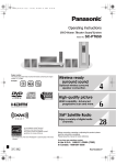
2.6.5
Standard Platform League
In Standard Platform League all teams use identical robots and is the most
popular. Therefore, the teams concentrate on software development only, while
still using state-of-the-art robots. The robots operate fully autonomously, i.e.
there is no external control, neither by humans nor by computers. In 2008 the
league goes through a transition from the four-legged Sony AIBO to the humanoid
Aldebaran Nao (Figure 2.6). Every team has four players and the games take
place in a 4m × 6m field marked with thick white lines on a green carpet. The
two colored goals (sky-blue and yellow until 2011) also serve as landmarks for
localizing the robots in the field. Each game consists of two 10-minute halves
and teams switch colors and sides at half-time. There are several rules enforced
by human referees during the game. For example, a player is punished with a
30-seconds removal from the field if he performs an illegal action, such as pushing
an opponent for more than three seconds, grabbing the ball between his legs for
more than three seconds, or entering his own goal area as a defender. The main
Figure 2.6: Standard Platform League game in Robocup 2008( Opponents should
be in different colors, but there was a lack of Nao robots in that event due to
malfunctions )
characteristic of the Standard Platform League is that no hardware changes are
Angeliki Topalidou-Kyniazopoulou
23
March 2012
2.7 Kouretes Team
allowed; all teams use the exact same robotic platform, which is developed by an
external robotics company and differ only in terms of their software. Given that
the underlying robotic hardware is common for all competing teams, research
effort has been focused on maximizing the efficiency of the hardware, the development of more efficient algorithms and techniques for visual perception, active
localization, omni-directional motion, skill learning, and coordination strategies.
During the course of the years, one could easily notice a clear progress in all
research directions.
2.7
Kouretes Team
Kouretes Team,is a robotic team that participates in SP L(Standard Platform
League) based at the Intelligent Systems Laboratory at the Department of Electronic and Computer Engineering. Until this date is the first Greek team participating in Robocup Soccer competition and especially in the Standard Platform
League and the MSRS Simulation League.Kouretes Team was founded in 2006
by Michail G. Lagoudakis, assistant professor at Department of Electronic and
Computer Engineering. The team’s name, Kouretes, comes from the Ancient
Greek Mythology and refers to Kouretes brothers Epimedes, Paionaios, Iasios,
Idas and Hercules.
Since 2008 and the transition in RoboCup SPL from the AIBO robot to the
NAO robot Kouretes Team develop their own open source code and their own
customized to their needs system tools. The team aims to develop independent
platform code for robots, but is still in early stages. The software architecture that
the teams uses separates the platform characteristics from the modules that process the information taken from the environment and configures those modules for
the specific platform. The main modules that Kouretes’ code is highly and occasionally absolutely bound to the robot’s middle-ware is the localization(Kouretes
use the robot model given from Aldebaran-robotics) and the motion(Aldebaran
walk) of the robot. Kouretes Team doesn’t use source code from other teams,
but uses the gained knowledge from their research in order to develop efficient
Angeliki Topalidou-Kyniazopoulou
24
March 2012
2.7 Kouretes Team
algorithms and techniques for information processing.
Kouretes have participated in many competitions, exhibitions, and affairs,
but the highlights of the steep orbit the team followed were the second place in
Robocup 2007, Atlanta, USA in the MSRS Simulation League, the first and third
place in Robocup 2008, Suzhou, China in the MSRS Simulation League, and the
Standard Platform League accordingly and the second place in Standard Platform
League’s Open Challenge Competition in Robocup 2011, Istanbul, Turkey.
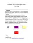
Figure 2.7: Kouretes team 2011 in Istanbul. From left to right sitting down are
Astero-Dimitra Tzanetatou, Iris Kyranou, Angeliki Topalidou- Kyniazopoulou. From
left to right standing up Emmanouel Orfanoudakis, Eleutherios Chatzilaris, Nikolaos
Spanoudakis, Michael Lagoudakis and Evangelos Vazaios .
More information and news of the team but also its members can be found at
http://www.kouretes.gr.
Angeliki Topalidou-Kyniazopoulou
25
March 2012
2.8 NAO Robot
Figure 2.8: Nao’s overview.
2.8
NAO Robot
NAO (Figure 2.8), in its final version, is 58 cm tall humanoid robot and weights
5.2 Kg. In 2012 Nao will be commercially released. According to Aldebaranrobotics over one thousand NAO robots have been sold since 2008 and until 2011
to universities and research institutions. The initial limited edition of the robot
(RoboCup edition v2) made its debut at RoboCup 2008. The Nao robot v4
that will be out to the market in 2012 carries a full computer on board with an
ATOM Z530 processor at 1.6 GHz, 1 GB RAM, and 2 GB flash memory running
an Embedded Linux distribution. It is powered by a Lithium-Ion battery which
provides about 60 minutes on active use or 90 minutes on normal use. NAO
robot communicates with remote computers via an IEEE 802.11g wireless or a
wired ethernet link. The NAO robot features a variety of sensors and actuators,
in order to understand the environment and act in it.
NAO has two cameras(Figure 2.9) on its head of type SOC Image sensor which
produce 30 images of 960p per sec. These two cameras can not function simultaneously, the robot can use only one camera at the time, so the choice of which
camera is on, is due to whether the object to observe is near or far away from the
robot. The perception of the environment concludes with the output of the two
Angeliki Topalidou-Kyniazopoulou
26
March 2012
2.8 NAO Robot
Figure 2.9: Nao’s field of View
ultrasonic sensors(also referred as sonars) that represent the obstacles that stand
25cm to 255cm away from the robot.In case an object is in front of the robot in
distance less than 15cm there is no information about the position of the object,
but only for its existence.
A rich inertial unit (two 1-axis gyrometer and a 3-axis accelerometer) in the
robot’s torso provides real-time information about its instantaneous body movements. An array of force sensitive resistors on each foot delivers feedback on the
forces aplied to the feet, while encoders on all servos record the actual joint position at each time and two bumpers on the feet provide information on collisions of
the feet with obstacles. Finally, a pair of microphones allows for stereo audio perception. The Nao robot has a total of 21 degrees of freedom; 4 in each arm, 5 in
each leg, 2 in the head, and 1 in the pelvis (there are 2 pelvis joints which are coupled together on one servo and cannot move independently). Stereo loudspeakers
and a series of LEDs complement its motion capabilities with auditory and visual
actions. Connecting to a robot is a major concept, thus Aldebaran provide us
two means of connection. The NAO robot, can be connected directly or sharing
the same network, through a wired ethernet link. Additionally, an IEEE 802.11g
wireless card is available, which is the frequent way of connection, due to the lack
of forces applied to the robot through the network cable. Through the wireless
Angeliki Topalidou-Kyniazopoulou
27
March 2012
2.8 NAO Robot
Figure 2.10: Embedded and Desktop software.
connection robots exchange data and during the soccer matches robots receive the
referee’s decisions. The NAO programming environment (Figure 2.10) is based
on the proprietary NaoQi framework which serves as a middle-ware between the
robot and high-level languages, such as C, C++, and Python. NaoQi offers a distributed programming and debugging environment which can run embedded on
the robot or remotely on a computer offering an abstraction for event-based, parallel and sequential execution. Its architecture is based on modules and brokers
which can be executed on board on the robot or remotely on pc’s and allows the
seamless integration of various heterogeneous components, including proprietary
and custom-made functionality.
In overall, Aldebaran Robotics designed and assembled a low-cost robot, which
can be a great platform used not only for scientific purposes, but entertainment as
well, easily programmable, focusing on the wide audience of robotics’ researchers
and fans. The development of humanoid robots is a tough procedure that only
few universities and companies have undergone, and even fewer were located in
Europe.
To be fair, we have to admit that the first version of Nao was not functional to
the level that Robocup teams would be satisfied. Nevertheless, most teams were
Angeliki Topalidou-Kyniazopoulou
28
March 2012
2.9 Monas architecture
able to present some basic soccer behaviors, confirming that even under these
limitations and the minimum available time for development, people involved in
Robocup gave their best shot.
2.9
Monas architecture
Monas architecture [2] is the software architecture developed by team Kouretes
for the NAO robot and for the robocup competition. While designing this architecture the engineer considers the robot as a collection of agents. Software
modules are running concurrently, having their own goals. They can use any
information available not only on the robot itself, but also information available
on the robot’s broader environment, for example other connected robots and
computers. Thus, the Monas framework aims to manage the robot’s software
modules, allocate the resources appropriately, and provide a principled process
for developing new modules. Additionally, Monas provides the necessary abstraction and platform independence, in both robots and computers, to allow
for source code reusability among software tools that ease the development of
agent’s components. The above, offers a justification for the architecture’s name:
Monas. According to the ancient Greek philosophers, the Pythagoreans, Monas
represents the first being, the indivisible, but also the totality of all beings. Its
symbol, a circle with a point at its center, has also been used in astronomy to
symbolize the sun, as well as by alchemists to represent gold. Hence, Monas, or
Μονάς in Greek, being a software architecture for robotic agents represents the
totality of the robot.
A major challenge for any software architecture is to provide a sufficient level
of abstraction for organizing the source code. To this end Monas decomposes
each module into activities. An activity refers to a simple discrete task that the
agent has the ability to perform. The activity is supposed to be as simple as
possible, but this is not enforced. Monas provided the developer with the necessary structure for organizing the code without compromising his/her freedom.
To deal with larger activities, Monas provides further decomposition of activities into functionalities. Functionalities are implementations of what an activity
Angeliki Topalidou-Kyniazopoulou
29
March 2012
2.9 Monas architecture
does and each activity must be associated with at least one functionality. Functionalities are source elements that implement very specific features found in the
bottom of the hierarchy. Although the latter decomposition step is not optional
in the design, it can be omitted in practice when there is no gain in decomposing the corresponding activity, for example when the implementation of the
activity-functionality pair counts only a few lines of code. Agent decomposition
also improves the code reusability as functionalities and activities can be freely
used without modification in as many activities and agents respectively as the
user likes. The developer can also trace the execution of the activities and thus
the modification and data creation throughout the agent cycle yielding better
debugging performance. Another advantage of the activity model is that agents
can be modified at runtime by adding and/or removing modules without having
to stop the execution of the architecture or even of the agent.
Monas architecture is designed to be a mobile architecture framework that
supports a variety of robotic platforms. The only platform requirements posed
by the architecture are the availability of a cpp (cross-) compiler for the on-board
computer and the appropriate configuration to accomplish the building. In order
to separate the user’s source code from the underlaying platform, Monas introduces an abstraction layer that consists form a set of interfaces. The set is divided
into two major sections: one that manages the robots sensors and actuators, and
one for managing platform specific and operating system issues. That approach is
appropriate because it separates the robot from its operating system and enables
the architecture to run on a personal computer while is configured for a specific
robotic platform.
To control the agent creation a primitive agent management system was implemented. Agents are defined in an XML file and instantiate at runtime. Each
agent runs at its own thread with its activities executed sequentially. The proposed approach has the advantage that is very easy to understand and use efficiently. Managing agents from an XML file that is required at the start of the
architecture, gives the developer the freedom to change the components of the
agent and create new agents without the necessity to recompile the source code.
Angeliki Topalidou-Kyniazopoulou
30
March 2012
2.9 Monas architecture
Monas also supports to start and terminate agents on the fly, by sending the
appropriate network message. Agent modification is also supported over the network but the interface is not implemented yet.
Another feature of Monas architecture is the use of statecharts. Following the
Agent System Engineering MEthodology, as described in section 2.11, it is very
easy to design and develop an agent or a multi-agent system. At this point statecharts are used by team Kouretes as an agent that controls the robot’s behavior.
Statecharts’ major difference from finite state machines and its derivatives is that
they natively support concurrency. The advantage of statecharts is that it allows
more than one state to be active simultaneously, in contrast to finite machines
that allow only one state to be active at the time. To support that in the engine
itself, without introducing loss of the system responsiveness, we split the execution of the engine into two parts. The first part is responsible for stepping the
engine and is executed in its own thread, whereas the second one is responsible for executing all the activities that are active at the time, implemented as a
thread pool. The implementation enables the developer to specify the maximum
number of activities that can be active simultaneously, managing the CPU load
and taking advantage of multi-cores CPU’s.
Monas’ statechart engine, can be used with the Narukom communication system for inter-activity and inter- statechart communication, giving the ability to
every activity, action and transition to directly access a Narukom instance, which
is unique within the underlaying statechart, and to a blackboard instance. Thus,
activities can communicate, actions can interact with the environment and transitions evaluate their conditions using the publish-subscribe system. The blackboard instance is not one for every statechart instantiation but its is scoped. The
scope include all the states between the lowest level OR-state that is a common
ancestor of both the source and target states. As a result, activities that live
in a different region of an AND-state will not have the same data at a specific
time, this does also apply to the evaluation of transitions expressions in which the
same condition may evaluate to true in a region whereas in an other one to false.
The communication model solves the synchronization issues that arise, such as
Angeliki Topalidou-Kyniazopoulou
31
March 2012
2.9 Monas architecture
the consumer-producer problem which occurs when an activity is executed more
times than another activity which uses data provided by the first, as well as the
starvation problem when multiple threads try to lock the same mutex simultaneously, that would have been occurred if have used a shared-memory model for
the communication.
Monas statechart engine implementation has slightly different semantics from
the Harrel’s Rhapsody tool [3]. Beyond the OR-state, AND-state and BASICstate, it defines the START-state and END-state, as in UML. Theses states are
introduced to formalize the default transition inside an OR-state and to indicate
that the inner state has reach its end of execution respectively. These states
are useful because they ease not only the development of the engine but also the
visual representation of the statechart. Also transition expressions can, of course,
be included in their outgoing and incoming transitions making further control of
the entrance and exit of an OR-stage formalized. Every state can have an entry
and an exit action. Actions differ from activities as they do not consider to
consume any, significant, computational time. Both actions are optional and will
be executed in the activation and deactivation of the state. An activity must be
assigned to a BASIC-state. On the activation of the state, the activity is enqueued
to the thread pool and is then executed, according to the thread pool internal
algorithm, on a separate thread. The activity is not executed endlessly as long
as the state is active but it only runs once. As long as the activity is running,
a shared mutex is locked so the states which share the same blackboard can
not step to ensure the correct execution of the statechart. Transition segments
support transition expressions which are represented visually as e[c]/a with ’e’
denotes the event, ’c’ the condition and ’a’ the action. The transition expressions
controls the execution of the transition: if the event match and the condition
evaluate to true only then the action is executed. In the transition algorithm
the event is disambiguated by the cpp typeid which indicates the class type of
an object at runtime. Transition segments can orientate and/or reach the states
that are described above or special states called connectors, forming compound
transitions. A compound transition can be either executed as a whole, which
means that every transition segment that participate must be executed, or not
Angeliki Topalidou-Kyniazopoulou
32
March 2012
2.10 Narukom
executed at all. From the connectors introduced in Rhapsody only the condition
connector is implemented. Other connectors can be implemented with ease as
the engine is written to be expandable. Transition segments are template classes
with arguments the source and the destination type. The type, which can be
either a normal state or the condition connector, is used by the compiler to select
the appropriate transition algorithm at compile time.
2.10
Narukom
Narukom [4] is the communication framework that the Kouretes team has developed and has been using for inter- and intra- robot communication as well
as robot-to-computer communication. Narukom is a message-based architecture
and provides a simple, efficient and flexible way of exchanging messages between
robots, without imposing restrictions on the type of the data transferred over
the network. The framework is based on the publish/subscribe paradigm and
provides maximal decoupling not only between nodes, but also between threads
on the same node.
The Narukom framework uses Google Protocol Buffers for the creation of its
messages. Protocol Buffers are a way of encoding structured data in an efficient,
flexible and extensible format and is being used by Google for almost all of its
internal Remote Procedure Call protocols and file formats. Data serialization and
de-serialization which is needed for network transmissions, especially between different platforms, is carried out by Protocol Buffers. Each message differs, except
from data type and data, in topic and message type. In order to read a message
the receiver should know where the desired message is published, ie its topic and
subscribe to that specific topic. The receiver should also know what the type of
the message is, Signal, State or Data. The publisher of the message determines
the topic and the type of the message and different publishers can publish in the
same or in a different way the same message. The meta-data contains the sender
node name, the publisher name as well as integrated temporal information in order to address synchronization needs. Moreover, Narukom provides a blackboard
to the publish/subscribe architecture. The blackboard is a software architecture
Angeliki Topalidou-Kyniazopoulou
33
March 2012
2.11 ASEME Methodology
model, in which multiple individuals share a common knowledge base. Individuals can read or update the contents of the blackboard and therefore cooperate to
solve a problem. It is common for blackboards to organize the containing knowledge as efficiently as possible to enable quick retrieval of data. The blackboard
in Narukom is available only between individuals that run on the same thread of
execution and provides full access, read/write, on local information and read-only
access to information that arrives from third-parties.
2.11
ASEME Methodology
The Agent Systems Engineering MEthodology (ASEME) [5] is an Agent Oriented Software Engineering (AOSE) methodology for developing multi-agent systems. It uses the Agent MOdeling LAnguage (AMOLA), which provides the
syntax and semantics for creating models of multi-agent systems covering the
analysis and design phases of a software development process. It supports a modular agent design approach and introduces the concepts of intra- and inter-agent
control. The former defines the agent’s behavior by co-ordinating the different
modules that implement his capabilities, while the latter defines the protocols
that govern the coordination of the society of the agents. ASEME applies a
model driven engineering approach to multi-agent systems development, so that
the models of a previous development phase can be transformed to models of the
next phase. Thus, different models are created for each development phase and
the transition from one phase to another is assisted by automatic model transformation, including model to model (M2M), text to model (T2M), and model
to text (M2T) transformations leading from requirements to computer programs.
The ASEME Platform Independent Model (PIM), which is the output of the
design phase, is a statechart that can be instantiated in a number of platforms
using existing Computer Aided System Engineering (CASE) tools, like the one
that this thesis presents.
The Agent Modelling Language (AMOLA) [6] describes both an agent and
a multi-agent system. The concept of functionality is defined to represent the
thinking, thought and senses characteristics of an agent. Then, the concept of
Angeliki Topalidou-Kyniazopoulou
34
March 2012
2.11 ASEME Methodology
capability is defined as the ability to achieve specific goals (e.g. the goal to decide
in which restaurant to have a diner this evening) that requires the use of one or
more functionalities. Therefore, the agent is an entity with certain capabilities,
including inter and intra-agent communication. Each of the capabilities requires
certain functionalities and can be defined separately from the other capabilities.
The capabilities are the modules that are integrated using the intra-agent control
concept to define an agent. Each agent is considered a part of a community of
agents, i.e. a multi-agent system. Thus, the multi-agent system’s modules are
the agents and they are integrated into it using the inter-agent control concept.
The intra-agent control concept allows the assembly of an agent by coordinating
a set of modules, which are themselves implementations of capabilities that are
based on functionalities. Here, the concepts of capability and functionality are
distinct and complementary.
The agent developer can use the same modules, but different assembling
strategies, proposing a different ordering of the modules execution producing
in that way different profiles of an agent. This approach provides an agent with a
decision making capability that is based on an argumentation based decision making functionality. Another implementation of the same capability could be based
on a different functionality, e.g. multi-criteria decision making based functionality. Then, in order to represent system designs, AMOLA is based on statecharts,
a well-known and general language and does not make any assumptions on the
ontology, communication model, reasoning process or the mental attitudes (e.g.
belief-desire-intentions) of the agents giving this freedom to the designer. The
AMOLA models are related to the requirements analysis, analysis and design
phases of the software development process. AMOLA aims to model the agent
community by defining the protocols that govern agent interactions and each part
of the community, the agent, focusing in defining the agent capabilities and the
functionalities for achieving them. The details that instantiate the agent’s functionalities are beyond the scope of AMOLA that has the assumption that they
can be achieved using classical software engineering techniques.
Angeliki Topalidou-Kyniazopoulou
35
March 2012
2.11 ASEME Methodology
The Agent System Engineering Methodology consists of three phases, the requirement analysis phase, the analysis phase and the design phase. In each phase
one or more models are created in order to produce the final output, the statechart that describes each part (agent) of the desired multi-agent system. In
the requirements analysis phase, AMOLA defines the System Actors and Goals
(SAG) and the Requirements Per Goal (RPG) models. In the analysis phase
AMOLA defines the System Use Cases model (SUC), the Agent Interaction Protocol (AIP) model, the System Roles Model (SRM) and the Functionality Table
(FT). In the design phase AMOLA defines the Inter-Agent Control (EAC) model
and the Intra-Agent Control (IAC) model. Although this thesis isn’t directly
connected to all of the ASEME phases, but to some of them it is useful to explain
shortly each developing phase.
The model for the requirements analysis phase according to AMOLA and
ASEME is the SAG model that is composed by the Actor diagram, containing
the actors and their goals. The SAG model is a graph involving actors who each
have individual goals. A goal of one actor may be dependent for its realization
to another actor; such a goal is also called dependum. The depender actor depends on the dependee in order to achieve the dependum. Graphically, actors are
represented as circles and goals as rounded rectangles. Dependencies are navigable from the depender to the dependum and from the dependum to the dependee.
Note that for simplicity of presentation, if a goal has no dependees is just drawn
next to the depender. The goals are then related to functional and non-functional
requirements in plain text form. An entity can qualify as an actor if it represents
a real world entity (e.g. a ”broker”, the ”director of the department”, etc).
After creating the SAG model the developer can pass the next step of requirements analysis phase in which is necessary to describe the requirements of the
desired goal. The Requirements Per Goal (RPG) is a simple model aiming to associate SAG goals to requirements presented in plain text form. In order to form
the RPG model the engineer would have to answer to the following questions for
each SAG’s goal:
Angeliki Topalidou-Kyniazopoulou
36
March 2012
2.11 ASEME Methodology
• Why does the actor have this goal and why does he depend to another for
it (this is the most important question and its answer is usually the goal’s
name)
• What is the outcome of achieving the goal (identify related resources)
• How is he expected to achieve this goal (identify the task to be performed
for reaching this goal)
• When is this goal valid (identify timing requirements)
After completing successfully the first ASEME phase(Requirements analysis
phase) the engineering can now easily develop the models of the next phase, the
Analysis Phase. The main models associated with this phase are the System Use
Cases model (SUC), the Agent Interaction Protocol model (AIP), the System
Roles Model (SRM) and the Functionality Table (FT). The SUC is an extended
UML use case diagram and the SRM is mainly inspired by the Gaia methodology [7]. Thus, a Gaia roles model method fragment can be used with minimal
transformation effort.
The use case diagram (SUC) helps to visualize the system including its interaction with external entities, be they humans or other systems. No new elements
are needed other than those proposed by UML. However, the semantics change.
In a use case diagram, the actor ”enters” the system and assumes a role and
agents are modelled as roles, either within the system box (for the agents that
are to be developed) or outside the system box (for existing agents in the environment). Human actors are represented as roles outside the system box (like in
traditional UML use case diagrams). The human roles are distinguished by their
name that is written in italics. This approach aims to show the concept that we
are modelling artificial agents interacting with other artificial agents or human
agents. The different use cases must be directly related to at least one artificial
agent role. The general use cases, also referred as capabilities, can be decomposed
to simpler ones using the include use case relationship. A use case that connects
two or more (agent) roles implies the definition of a special capability type: the
participation of the agent in an interaction protocol. A use case that connects
Angeliki Topalidou-Kyniazopoulou
37
March 2012
2.11 ASEME Methodology
Operator
Interpretation
x. y
x followed by y
x|y
x or y occurs
x?
x occurs 0 or more times
x+
x occurs 1 or more times
x˜
x occurs infinitely
[x]
x is optional
x || y
x and y interleaved
Table 2.1: Operators for Liveness Formula(Table 1 from ”THE AGENT SYSTEMS ENGINEERING METHODOLOGY (ASEME)”)
a human and an artificial agent implies the need for defining a human-machine
interface (HMI), another agent capability. A use case can include a second one
showing that its successful completion requires that the second also takes place.
An AIP (the reader should take care not to confuse it with the AIP model
of AUML [8], for the remainder of this document AIP will refer to the AMOLA
model) defines one or more participating agent roles, the rules for engaging (why
would the roles participate in this protocol), the outcomes that they should expect in successful completion and the process that they would follow in the form
of a liveness formula. The liveness formula is a process model that describes
the dynamic behavior of the role inside the protocol. It connects all the role’s
activities using the Gaia operators (Table 2.1). The liveness formula defines the
dynamic aspect of the role, that is which activities execute sequentially, which
concurrently and which are repeating.
The System Roles Model (SRM) is mainly inspired by the Gaia roles model [7,
Angeliki Topalidou-Kyniazopoulou
38
March 2012
2.11 ASEME Methodology
9]. A role model is defined for each agent role. The role model contains the
following elements: a) the interaction protocols that this agent will be able to
participate in, b) the liveness model that describes the role’s behavior. The
liveness model has a formula at the first line (root formula) where activities or
capabilities can be added. A capability must be decomposed to activities in a
following formula. The liveness formula grammar has not been defined formally
in the literature, thus it is defined here using the Extended Backus-Naur Form
(EBNF) [10], which is a metasyntax or metametamodel notation used to express
context-free grammars. It is a formal way to describe computer programming languages and other formal languages. It is an extension of the basic Backus-Naur
Form (BNF) metasyntax notation. EBNF was originally developed by Niklaus
Wirth (1996). The EBNF syntax for the liveness formula (Table 2.2), using the
BNF style followed by Russell and Norvig [11], i.e. terminal symbols are written
in bold.
The Functionality Table (FT) the last step of the analysis phase is where the
analyst associates each activity participating in the liveness formulas of the SRM
to the technology or tool (functionality) that it will use.
After completing the functionality Table the engineer can pass to the design phase in which EAC and IAC models are created. The Inter-Agent Control
(EAC) is defined as a statechart. It should be initialized by transforming the
agent interaction protocols of the analysis phase to statecharts. Harel and Kugler
(2004) [3] present the statechart language adequately, but not formally. David’s
UML semantics [12] for statecharts has been used as basis for the definition of
the AMOLA statecharts as it is the first intended for object-oriented language
implementation. These models not only formally describe the elements of the
statechart, they also focus on the execution semantics. It is assumed that, as
long as the language of statecharts is not altered, a statechart can be executed
with any semantics available depending on the available CASE tool. The formal
model that is adopted here-in is a subset of the ones presented in the literature as
there are several features of the statecharts not used herein, such as the history
Angeliki Topalidou-Kyniazopoulou
39
March 2012
2.11 ASEME Methodology
→formula
→leftHandSide ” = ” expression
→string
→term
→| parallelExpression
→| orExpression
→| sequantialExpression
parallelExpression →term ”||” term ”||” ... ”||” term
orExpression
→term ”|” term ”|” ... ”|” term
sequentialExpression→term ”.” term ”.” ... ”.” term
term
→basicTerm |”(” expression ”)”
→|”[” expression ”]”
→| term ” ? ”
→| term+
→| term ”˜”
→|”|” term ”˜|” number
basicTerm
→string
number
→digit | digit number
digit
→”1”|”2”|”3”| ...
string
→letter | letter string
letter
→”a”|”b”|”c”| ...
liveness
formula
leftHandSide
expression
Table 2.2: The liveness formula grammar in EBNF format
Angeliki Topalidou-Kyniazopoulou
40
March 2012
2.11 ASEME Methodology
states (which are also defined differently in these works).
Before formally defining the statechart for the EAC model, the elements that
compose the transition expressions are examined. Then, the transition expressions are defined in EBNF. Transitions are usually triggered by events. Such
events can be:
1. a sent or received (or perceived, in general) inter-agent message
2. a change in one of the executing state’s variables (also referred to as an
intra-agent message)
3. a time-out
4. the ending of the executing state activity
The latter case is also true for a transition with no expression. Note that each
state automatically starts its activity on entrance. A message event is expressed
by P(x,y,c) where P is the performative, x is the sender role, y the receiver role
and c the message body. The items that the designer can use for defining the
state transition expressions are the message performatives, the ontology used for
defining the messages content and the timers. An agent can define timers as normal variables initializing them to a value representing the number of milliseconds
until they time-out (at which time their value is equal to zero). The transition
expressions can use the time-out unary predicate, which is evaluated to true if
the timer value is equal to zero, and false otherwise. Timers are initialized in the
action part of a transition expression, while the time-out predicate can be used
in both the event and condition parts of the transition expression depending on
the needs of the designer.
Besides inter-agent messages and timers there is another kind of events, the
intra-agent messages. The change of a value of a variable can have consequences
in the execution of a protocol. The variables taking part in a transition expression imply the fact that they are defined in the closest common ancestor OR
Angeliki Topalidou-Kyniazopoulou
41
March 2012
2.12 Eclipse Modeling Project
state of the source and target states of the transition or higher in the statechart nodes hierarchy. The intention regarding the performative definition is not
to enumerate all possible performatives, the modeler can define such as he sees fit.
In the agent level, the Intra-Agent Control (IAC) is defined using statecharts
in the same way with the Inter-Agent Control model (EAC). The difference is
that the top level state (root) corresponds to the modeled agent (which is named
after the agent type). One IAC is defined for each agent type.
2.12
Eclipse Modeling Project
The Eclipse Modeling Project ( EMP ) [13] provides several frameworks for
defining a Domain Specific Language (DSL) and develop software for this language. EMP allows the developer to createtools supporting for Model-Driven
Software Development ( MDSD ), which is useful for the development of agents.
EMP consists of EMF ( Eclipse Modeling Framework ) [14], QVT ( Query: Validation: Transaction ), M2M ( Model-to-Model transformation ), M2T ( Modelto-Text transformation ), TMF ( Textual Modeling Framework ) and GMF (
Graphical Modeling Framework ). EMF allows the developer to define a DSL
language in an abstract syntax. EMF has as an output a model that describes a
new language. QVT provides query, validation and transaction features for the
EMF models. M2M provides Operational Mapping Language that allows modelto-model transformation for EMF models. M2T allows model-to-text by using
JET ( Java Emitter Template ) or Xpand as a template engine. TMF is still under
development and does not offer a lot of capabilities, but its purpose is to provide
a textual editors with syntax highlighting, code completion and build for EMF
models. In the other hand, GMF provides graphical editors for EMF models.
2.13
Xpand and IAC-2-Monas
Xpand language was proposed by Open Architecture Ware (oAW) and is used
for Model-to-Text (M2T) transformations. The language is offered as part of the
Eclipse Modeling Project (EMP). The language allows the developer to define a
Angeliki Topalidou-Kyniazopoulou
42
March 2012
2.13 Xpand and IAC-2-Monas
set of templates that transform objects that exist in an instance of a model into
text. Major advantages of Xpand are the fact that it is source model independent,
which is usually source code but it can be whatever text the user desires, and its
vocabulary is limited, allowing for a quick learning curve. The language requires
as input a model instance, the model and the transformation templates. Xpand
first validates the instance through the provided model and then, as the name
suggests, expands the objects found in the instance with the input templates.
It allows the user to define, except form the expansion templates, functions implemented in Java language using the Xtext functionality. Xpand is a markup
language and uses the ”<<” and ”>>” to mark the start and the end of the
markup context. Enables code expansion using the model structure (i.e. expanding all child elements of a specific type inside a node) and supports if-then-else
structure. Functions call be called inside markup. The advantages of Xpand are
the fact that it is source model independent, its vocabulary is limited allowing
for a quick learning curve while the integration with Xtend allows for handling
complex requirements. Then, EMP allows for defining workflows that can help a
modeler to achieve multiple parsings of the model with different goals.
IAC-2-Monas is a code generator, which extracts a statechart model in C++
language compatible with Monas architecture (see section 2.9) from a IAC model
(see section 2.11). IAC-2-Monas was developed by Alexandros Paraschos [2] for
Kouretes. IAC-2-Monas is developed in Xpand and java language and uses these
java packages:
• org.eclipse.emf.mwe.utils.Reader
• org.eclipse.xpand2
• java.util.HashSet
• java.util.List
• java.util.Set
• java.util.StringTokenizer
Angeliki Topalidou-Kyniazopoulou
43
March 2012
2.13 Xpand and IAC-2-Monas
• java.util.regex.Matcher
• java.util.regex.Pattern
• java.util.Comparator
• IAC
Angeliki Topalidou-Kyniazopoulou
44
March 2012
Chapter 3
Problem Statement
3.1
Soccer Team Formation
The main properties of a soccer team are the coach, the players and the formations the team uses during the matches. Every player has a specific role in a
match and especially in every formation. It is very important for a soccer team to
have various formations available for each match, and its players role to be flexible
enough for every situation. All of the above are part of coach’s job. The coach is
responsible for the harmonic cooperation of all teammates and the district soccer
player roles.
3.2
Robot Behavior
Every robot is an autonomous agent. In order to design an agent (robot)
that reacts with the environment in a desired way, one would have to define the
robot’s behavior. The behavior of the robot is the module, or the part of the
robot’s software that collects the calculated information from the environment
and makes decisions. So, the decision making module of the robot is called
behavior. It is important for the developer to be able to define or change the
robot’s behavior in a simple and quick way and that’s what thesis presents to
you.
Angeliki Topalidou-Kyniazopoulou
45
March 2012
3.3 Design Behavior
3.3
Design Behavior
It is very important for software engineers, who compete in RoboCup Soccer
competitions to be able to adjust easily and fast the existing robot behaviors
to any occasion. It is also important to have the ability to design quickly a
robot behavior in an abstract way from scratch and develop modules that would
be reusable for other behaviors too. Kouretes team having previous experience,
since the team competes in Standard Platform League since 2006, has concluded
in the need of developing a handful tool for easy editing of an agent in the
form of statechart and given a semi-automated code generation. The team has
designed its software architecture, Monas, in a way that it would fit to the ASEME
methodology output. ASEME gives the programmer a structured methodology
of designing an agent or even a multi-agent system. That is the value of ASEME
that Kouretes team wanted to exploit in every mean. In order to do so it is
critical to design an application or a software tool that connects the ASEME
output to the Monas code. As described in section 2.11 ASEME’s output is a
statechart for the inter and intra-agent that lays in an abstract form. Hence,
Kouretes would have to find an easy way to implement the ”abstract” ASEME’s
output to compatible code for Monas.
3.4
Related work
Although there are a lot of CASE tools available, we will present three of them
that are quite similar to our approach and used technologies.
3.4.1
Yakindu
Yakindu (Figure 3.2) is an free toolkit for the model driven development of
embedded systems. Through the systematic use of models, it aims at an integrated development process as well as an increase in quality and maintainability.
The Yakindu toolkit supports the development of both reactive, event-driven and
data flow-oriented systems with the help of statecharts and block diagrams. The
continuous support begins with graphical modelling tools, includes integrated
Angeliki Topalidou-Kyniazopoulou
46
March 2012
3.4 Related work
validation and simulation, that allows for the early assessment of the models
and offers efficient code-generators for the generation of source code for a target
platform. Technologically, it is based on Eclipse-platform and integrates itself
seamlessly into Eclipse-based workbenches and extends this in the direction of
model-driven development. The Yakindu toolkit allows to design embedded systems by using both statecharts and block-diagrams (Figure 3.1).
Figure 3.1: Design of an Heating Control embedded system.
Figure 3.2: Yakindu Environment
Angeliki Topalidou-Kyniazopoulou
47
March 2012
3.4 Related work
The Yakindu Statechart Tools (SCT) allow graphical modeling based on
Harel-statecharts [15]. They support all essential concepts like extended state
variables, hierarchical states, orthogonal states (also known as And-States or
parallel regions) or History-States. This corresponds to the concepts that are
used in modelling languages such as UML. The convenient model-editor integrates features such as model validation and simulation as well as the generation
of source code.
Furthermore, the ”Yakindu Toolkit” includes the data flow-oriented modelling
environment Damos (Figure 3.3), which enables the generation of block diagrams,
the simulation of models and the code generation for a target platform. Due to
the modular and open structure, aspects of the modelling environment can be
adapted to individual needs. This includes the development of one’s own blocks,
whereby here the tailored data flow-oriented systems scripting language Mscript
can be used to specify the behavior of the blocks.
Figure 3.3: Damos Block Diagram
Both SCT and Damos already during the modelling execute consistency checks
on the models. Examples are the tests for unavailable conditions in statecharts
and the verification for correct calculations with SI-units in Damos. During the
processing of the models, the developer receives with it a feedback or an acknowledgment early on if such consistency conditions are violated.
Angeliki Topalidou-Kyniazopoulou
48
March 2012
3.4 Related work
Through the simulation(Figure 3.4, the actual run-time behavior of finite-state
machines and block diagrams are tested and validated early on in the development process as to whether the models implement the requirements of the system
correctly. As a result, a class of errors found by the consistency checks described
above can remain undetected and can just be poorly traced through visual inspection. The simulation engines of SCT and Damos integrate themselves into
the Eclipse-Workbench and allow the direct execution of the models.
Figure 3.4: Simulation
The Damos and SCT-Code-Generators allow the automatic mapping of the
models to source code that can be integrated into the respective embedded
software. Both Damos as well as SCT support Out-Of-The-Box C as a target
language-SCT additionally also Java. These code generators can be directly applied and generate efficient implementations.
3.4.2
Xabsl Editor
The Extended Agent Behavior Specification Language (XABSL) [16] is a simple
language to describe behaviors for autonomous agents based on hierarchical finite
state machines. XABSL was developed by the RoboCup Soccer team GermanTeam to design the behavior of soccer robots. The usage of the language is not
restricted to robotic soccer. XABSL is a good choice to describe behaviors for all
Angeliki Topalidou-Kyniazopoulou
49
March 2012
3.4 Related work
kinds of autonomous robots or virtual agents like characters in computer games.
Figure 3.5: XABSLEditor
For XABSL there is a corresponding editor, the XABSLEditor (Figure 3.5).
The XABSLEditor was developed by the Nao Team Humbolt in 2008 and allows
the user to describe agents and behaviors by using the XABSL language. This
editor is basically a text editor for XABSL, but also represents graphically the
hierarchical finite state machines that describe the agents behavior. It also provides a compiler for XABSL.
XABSLEditor:
• runs on all platforms (since it is written in Java)
• open source (all used components are open source to)
• has syntax highlighting
• provides live view of the state graph
Angeliki Topalidou-Kyniazopoulou
50
March 2012
3.4 Related work
• has auto completiona ability:
– completion of symbols with parameters and enums
– live documentation (generated from comments)
• has live syntax check (errors are red underlined, without of recompiling of
the whole project)
• has multiple tabs, thus multiple open editors
• can jump to an option definition (a click on an used option opens the file
were the option is defined)
• has a build in compiler (ruby has not to be necessary installed)
• has a search feature (in files and in the whole project)
• allows unlimited undo/redo
3.4.3
An Interactive Editor For The Statechart’s Graphical Language
The Statechart Editor, which was developed by Stephen Edwards for Statechart’s graphical language, which uses a hierarchy of interacting finite-state machines. The editor is written using the incr Tcl add-on to the Tcl/Tk language.
The editor keeps transitions attached, and allows for multiple, consistent views
of the database. The objective of this project was to produce a graphical, interactive editor for the Statechart’s graphical language, which uses hierarchicallyarranged finite state machines.
A Statechart (Figure 3.6) contains two sorts of entities: states, which are boxes
with names, and transitions, which are curved arrows connecting two states.
The editor can:
• add and delete states and transitions
Angeliki Topalidou-Kyniazopoulou
51
March 2012
3.4 Related work
Figure 3.6: Interactive Editor For The Statechart’s Graphical Language
• move states and transitions, either preserving hierarchy or modifying it
• When states move, transitions remain attached. Transitions’ shapes either
come from a single index of curvature, or can be specified arbitrarily by the
user.
• edit multiple views of the database, each starting from a different state in
the hierarchy, going down a different depth, and with different magnification
• edit attributes (fonts, colors, shape) of states and transitions in dialogs read
and write the database to disk
• print a view of the database to a PostScript file
This editor is written using McLennan’s incr Tcl package, which brings an
object-oriented data model to Tcl.
Angeliki Topalidou-Kyniazopoulou
52
March 2012
Chapter 4
Our Approach
4.1
The Design of a Behavior
Kouretes team needs a tool for soccer player behavior development. This tool
should allow the user to design quickly a new behavior or change easily an existing
behavior. A nice and user friendly way of describing a behavior is by describing
it graphically. The behavior of an (robot) agent usually consists of if/else if
loops, because it has to describe an action for every possible event. A good way
of describing such a behavior is an Finite State Machine, or any kind of state
machines. It is very common to design state graphs in order to describe system
behavior, data flow, class hierarchy or even an algorithm.
4.2
Graphs
For an algorithm represantation, one could use a flow chart. For a class hierachy representation he could use a UML diagram. If someone would like to
describe the ”flow” of data through an information system, he could use a data
flow diagram. In case of system behavior, someone could use Finite State Machines(FSM) (Figure 4.1) hierarchical or not and statecharts. For our appoach
we chose statecharts(Figure 4.1). Statecharts offer the great values of FSMs and
multi-thread execution, since when AND nodes exist in a statechart the children
nodes OR are executed in parallel. In an FSM only one state can be active, that’
Angeliki Topalidou-Kyniazopoulou
53
March 2012
4.3 The Representation of a Behavior
Figure 4.1: Left image: FSM. Right image: statechart.
s not the case with statecharts because of the parallel execution.
4.3
The Representation of a Behavior
It is crucial to a behavior developer to have a graphical representation of the
designed behavior or even to be able to design and edit it graphically. Kouretes
team for years had been developing agent behavior as one class that makes the
decision for robot’s actions. That approach leads to a huge class full of if/else
if loops and overpopulated functions in one block, which is also difficult to
understand and debug. Kouretes team decided that a graphical representation of
an agent as a statechart would be more clear to a developer and also easier to
design and edit. So, Kouretes now design robot behaviors as statecharts, which
facilitate the graphical representation of complex behaviors.
4.4
Methodology of designing robot behaviors
On the one hand statecharts provide a useful representation of a complex behavior, on the other hand it is time consuming to describe graphically a complex
behavior state by state and transition by transition. In conclusion it is easy to
understand an existing statechart with a graphical representation, but it is ”difficult” to create one from scratch. In order to overcome the time consuming initial
representation Kouretes team decided to exploit the ASEME models. ASEME
Angeliki Topalidou-Kyniazopoulou
54
March 2012
4.4 Methodology of designing robot behaviors
provides an analysis phase and a design phase. The analysis phase helps the developer make clear the desired goals of the agent and the way of achieving them.
In addition, the liveness formula that lies at the analysis phase allows the user to
describe in quick and comprehensive way a complex behavior. The design phase
allows the developer to describe the model of behavior that came out from the
analysis phase. The developer can and should describe the model’s functionalities
int he analysis phase and the transitions’ expressions int the design phase. So,
we would need a tool, which provides the means for editing the models from the
analysis and design phase as well. The model from the analysis phase would be
described by liveness formulas has text form and the model, which would come
out as a result, is the IAC model (Figure 4.2) that has the form of a statechart.
As you can conclude ASEME can provide us the representation of the desired
behavior in a statechart at the end of the two phases.
Figure 4.2: IAC model according to EMF
IAC model consists of:
• Model has a name and contains nodes, transitions and variables and represents the statechart
• Node contains one or more variables and nodes and represents statechart’s
states and has:
Angeliki Topalidou-Kyniazopoulou
55
March 2012
4.5 From Statechart Description to Robot Behavior
– name
– label, which is unique and indicates the state’s execution sequence
– type, which indicates state’s type(values: OR, AND, START, END,
CONDITION and BASIC)
– activity, this attribute is null for every type of states except BASIC
states and contains the state’s source code or a reference to a source
file
• Transition has name and TE (Transition Expression), TE consists of transition’s event, condition and action. Transition has as source and target a
model’s node
• Variable has a name and a type and belongs to one or more nodes.
4.5
From Statechart Description to Robot Behavior
Statecharts in a model form or an image form is something that a machine
(robot) can not ”understand”. So, we would have to find a way to translate the
statecharts into source code. Monas architecture has a statechart engine that
executes statecharts on the robot. Statecharts as source code for Monas consist
of these classes:
• Statechart that represents the execution sequence of states and transitions
• States (or, and, start, end, condition, and basic)
• Activitiies of each basic state
• Transition and its parts:
– Event
– Condition
– Action
Angeliki Topalidou-Kyniazopoulou
56
March 2012
4.6 CASE tool Functionlities
For this purpose a code generator is necessary to use. The code generator
should translate the statechart’s model from IAC model to the Monas’ statechart
architecture. So, a IAC’s TE will we be generated as event, condition and/or
action classes, basic state’s activity we be generated as activity, model will be
generated as statechart and it will contain model’s states and transitions.
4.6
CASE tool Functionlities
Considering the above, Kouretes team needs a CASE tool that allows the developer to edit the liveness formulas, in text form, and the statechart, in a graphical
way. So, a text editor for liveness formulas and a graphical editor is necessary.
Besides the editors, a CASE tool should provide more functions in order to facilitate the developer’s work. An important charectistic of the ASEME’s IAC model
is that its node has a label that is unique and indicates the execution sequence.
If someone designs a statechart graphically without writing the liveness formulas
from the analysis phase, he would have to add each state’s label very carefully
in order to obtain label’s uniqueness and sequence indication. That’s is a functionality that a tool should do automatically whenever the developer thinks it is
necessary.
Furthermore, a code generator should be part of a CASE tool, since the purpose of a CASE tool is system development. In order to describe the functionalities of each statechart class we would have either to write code on the diagram
for each element or edit each element’s code in a seperate editor. For complex
behaviors it would be chaotic to represent each elements code on the diagram,
so it would be better to write only the descritpion of transitions and edit state’s
code in a seperate editor.
When desinging a statechart it is very important to know if the model obeys
to the defined syntax and/or semantics. Since the IAC model describes a statechart that follows the Harel’s statemate’s semantics and rules, there should be a
validation functionality that alerts the developer for any mistakes and misuses of
the rules.
Angeliki Topalidou-Kyniazopoulou
57
March 2012
Chapter 5
Implementation
Kouretes team needed a graphical user interface(GUI) for creating soccer player
behaviors following the ASEME methodology. Although a soccer player behavior
is an agent and ASEME is a methodology for developing agents, Kouretes do not
perform all the steps and do not design all the models of ASEME. In summary,
the procedure needed for the design of a soccer player behavior for Kouretes is:
• Creation of liveness formula (according to AMOLA)
• Liveness to statechart transformation (according to ASEME’s IAC model)
• Graphical representation and editing of the created statechart
• Statechart model to C++ code for Monas transformation
5.1
The choice of platform and its benefits
In order to design the CASE tool for the Kouretes team, it is necessary to
choose the platform of implementation. As the IAC model was implemented
as an EMF (Eclipse Modeling Framework) model and the liveness to statechart
transformation was implemented in java, it was dictated to develop the CASE
tool in java by using the GMF (Graphical Modeling Framework) provided by IBM
and eclipse. For every new class that we add to the generated GMF application we
have to declare it to the MANIFEST.MF file to the extension points and add the
required dependencies to the homonym MANIFEST’s section. For implementing
Angeliki Topalidou-Kyniazopoulou
58
March 2012
5.2 The GMF models
this thesis we had to install the Eclipse Modeling Tools release of eclipse and
some additional packages and components:
• Eclipse Modeling Framework
• Graphical Modeling Framework
• OCL tools
• Xpand SDK
• Xtext SDK
• delta pack
5.2
The GMF models
The GMF provides some models in order to initialize the graphical definition
of an EMF model. The models are simple and provide a large variety of shapes
and colors. In order to use correctly the GMF we used the GMF DashBoard
(Figure 5.1), which shows all the necessary models for implementation and their
dependencies. Since the developer has described the desired EMF model, he
can define its graphical definition via the Graphical Definition Model. Another
model that the developer should describe, is the Tooling Definition Model, which
is responsible for the EMF model’s creation tools definition. As long as the developer has defined the models mentioned above, he can link the desired graphical
representation to the respectively creation tool via the definition of the Mapping
Model. The developer can also define the rules that the model should obey via the
same model. After the completion of the steps mentioned above, the developer
can create and edit the Diagram Editor Generate Model in order to complete the
definition of the EMF model’s graphical editor and finally generate it.
During the process of development it became clear that the IAC model (Figure 4.2) needed to be changed in order to represent graphically the models as
desired, thankfully only one small change made the difference. IAC, as implemented, did not give us the ability to design the children nodes inside the parent
Angeliki Topalidou-Kyniazopoulou
59
March 2012
5.2 The GMF models
Figure 5.1: The implementation procedure for GMF.
node, but it only allowed us to represent them in a tree form. The solution was
very easy to implement and didn’t affect the characteristics of the model, a new
relationship was entered which defined that a node can contain nodes as children.
The new EMF model has been named StateChart with file extension stct (Figure 5.2) and its graphical representation looks alike the STATEMATE semantics
of statecharts [17].
In order to make clear that the IAC model was not serving our purpose, we
created a simple GMF graphical editor and initialized Kouretes Goalie behavior(Figure 5.3) and did the same for STCT representation (Figure 5.4) that has
been developed for this thesis.
As you can see the representation of IAC model makes it difficult to navigate
through the designed model in comparison to the representation of the STCT
model. Since we had a handy EMF model we had to describe the graphical
representation of each model element as the Graphical Definition Model of GMF.
Nodes of different type should have different representation :
• START node should be a small black circle
• CONDITION node should be a circled C
• OR node should be a yellow labeled rectangle that contains START, CONDITION, OR, BASIC, AND and END nodes
Angeliki Topalidou-Kyniazopoulou
60
March 2012
5.2 The GMF models
Figure 5.2: STCT model according to EMF
• AND node should be a light blue rectangle that contains two or more OR
nodes
• BASIC node should be a green rectangle
• END node should be a white circle with a small black circle in its center.
Although the model has a lot of relationships between its elements it was a
necessity to not represent all of them in order to keep the diagram simple and
clean. The relationships that are represented are :
• transitions between nodes as an arrowed connection starting from the source
node and pointing to the target node
• children nodes of an OR or an AND node inside of the parent node
In addition, variables are represented as a bright green rectangle outside the
nodes. For setting a variable as a node’s variable we should select the desired
Angeliki Topalidou-Kyniazopoulou
61
March 2012
5.2 The GMF models
Figure 5.3: Goalie example in IAC representation
node and select the variables relationship from the properties view.
According to GMF after creating the Graphical Definition Model it is necessary to define the creation tools of its element in the Tooling Definition Model.
It is important to mention that we didn’t add creation tools for every element
and relationship of the EMF model. We could not have a creation tool for the
relationship ”variables”, because we didn’t defined its representation. We also
could not define a creation tool for the relationship ”children”, this relationship
is created as the user adds the new node in an another node.
Since the Graphical Definition Model and the Tooling Definition Model are defined we then need to connect them through the definition of the Mapping Model.
At this phase the programmer can define the validation rules of the model, if
any, and its error or warning messages. Since we have different representations
Angeliki Topalidou-Kyniazopoulou
62
March 2012
5.2 The GMF models
Figure 5.4: Goalie example in STCT representation
and creation tools for the element node, according to the value of its ”type”, we
have to use the OCL and define the constrains and restrictions for each different
representation and creation tool. For the validation rules we chose java as the
language of implementation and we will analyze this phase of implementation at
the next section.
When all the above definitions are complete the programmer can define some
extra features for the graphical editor, such as print action, live or not validation,
the file’s extension etc in the Diagram Editor Gen Model, which is the model
that organize the code generation for the defined graphical editor. For our im-
Angeliki Topalidou-Kyniazopoulou
63
March 2012
5.3 Validation Rules
plementation we chose the extra features: live validation, validation decorators,
print action and the generation of the editor as an eclipse application. Now the
programmer can use the GMF generator for generating the basic functions of the
Statechart editor. The generated application is based on eclipse environment and
it is basically a customized eclipse. If the target group of users use the eclipse
modeling components it is more convenient for them to use the eclipse plug-in,
but if they do not use the eclipse modeling version or not even the eclipse platform, the generated application is the best choice.
The generated application uses the GMF runtime package and provides implemented actions, commands, view edit parts, view policies, view provider, validation provider, properties sheet etc. If someone wants to develop easily a graphical
editor for a model GMF provides various functionalities and makes a great case,
but it has some problems also. The GMF’s disadvantage is that the implemented
provider for cut-copy-paste actions is not functional and the programmer should
write its implementation by hand. Another disadvantage of GMF is that once
the programmer describes the graphical representation of an element that can’t
change. For example, if someone wants to select when an element’s attribute will
be visible and when not, that is not possible.
5.3
Validation Rules
In order to be able to create a statechart that obeys to the ASEME rules and
the transition’s grammar we had to define some validation rules. Firstly, we had
to be sure that the designed statechart follows the statechart rules, which are:
• StateChart Model can have only one root node of type OR.
• Every OR node should have exactly one START node as a child.
• Every OR node can’t have more than one END nodes as children.
• A START node can only be a source node for an transition.
• An END node can only be a target node for a transition.
Angeliki Topalidou-Kyniazopoulou
64
March 2012
5.3 Validation Rules
• An AND node can only have OR nodes as children.
In order to have code generation for the transitions, we had to define EBNF
grammar that enables the easy description of a more complicated class definition.
Since the EBNF grammar has been declared, we had to add a validation system.
The grammar that should be checked is:
TransitionExpression = [event][”[” condition”]”][/actions]
event = string
condition = expr
| expr (compOp | logicOp) condition
| ”(”condition”)”
| notOp condition
actions = TimeoutAction
| Actions
Actions = Actions connectiveOp action
action = ”process messages”
| ”publish all”
| ”publish” ”.” topic”.”commType”.”msgType”.”membersetfunction”(”val”)”
TimeoutAction = TimeoutAction”.”topic”.”time
expr = varVal | func ”(” args ”)”
func = < any valid cpp decleared f unction name >
| TimeoutCheck ”(” topic ”)”
args = varVal
| varVal ”,” args
varVal = message | variable | value
value = constant | stringLiteral | number+
compOp = ” < ”|” <= ”|” > ”|” >= ”|” == ”|”! = ”
logicOp = ”&&” | ”||”
notOp = ”!”
connectiveOp = ”;”
message = topic ”.” commType ”.” msgType
Angeliki Topalidou-Kyniazopoulou
65
March 2012
5.3 Validation Rules
variable = message ”.” member
commType = ”Signal”|”State”|”Data”
host = string
topic = string
msgType = string
member = string ”(” number? ”)” ( ”.”string ”(” number? ”)” )
membersetfunction = string ( ”(” number? ”)” ”.” string)?
time = number +
stringLiteral = ” string ”
string = letter (letter | number | ” ” )?
letter = ”a” | ”A” | ”b” | ” B” | ”c” | ”C” | ”d” | ”D” | ...
number = ”0” | ”1” | ”2” | ”3” ...
We also added validation for the variables, a variable’s name should start
with letter or ” ” and its type should be described as Narukom message, ie as the
messages described at the transition’s grammar.
For the above rule definitions we had to edit the generated code, since we
chose java as the language of implementation. The generated functions that we
had to edit were the ”validate” empty functions for every rule that were part of
the ValidationProvider class. For the correct description of a transition and a
variable we used regular expressions. For every part of the generated code that
we edited we had to put the flag:
/*
* generated NOT
*/
in order to keep that code unchanged from a possible next code generation, for
example if we wanted to change the representation of a model’s element or add
a new rule.
Angeliki Topalidou-Kyniazopoulou
66
March 2012
5.4 From graphical editor to CASE tool
5.4
From graphical editor to CASE tool
The GMF Framework enabled us to describe graphically our model and create
easily an application that allows us to edit it, but this is not enough for making
an application that helps a code developer to design a behavior for a robot soccer
player. Our purpose is to design and implement a useful CASE tool for modeldriven software development. This CASE tool has been named KSE (Kouretes
Statechart Editor). For our KSE implementation the statechart editor from GMF
can not be considered as a CASE tool. There are missing a lot of functions, such
as:
• liveness formula editor
• liveness formula to statechart transformation ( Text-to-Model (T2M) transformation)
• copy-cut-paste functionality for graphical views, this is not supported by
GMF
• statechart to Monas statechart transformation ( Model-to-Text (M2T) ),
also known as code generation
• statechart connection to Monas architecture and local repository
• editing of activities, BASIC states that are already implemented in C++
code in users’ local repository
• the automated labeling of model’s elements for proper code generation
5.4.1
Liveness Formula Editor
A special editor has been implemented for liveness formula (Figure 5.5). The
user can enter the model’s/formula’s name and the liveness formula itself. This
editor is implemented as a JFrame class from javax.swing package and has
a plain JTextArea from the same package for editing the formula’s name and
another one for editing formulas as well. The same editor appears when the user
chooses the action ”Open Formula” from the file menu.
Angeliki Topalidou-Kyniazopoulou
67
March 2012
5.4 From graphical editor to CASE tool
Figure 5.5: The Liveness Formula Editor
5.4.2
Liveness Formula to Statechart Transformation
The transformation of liveness formula to IAC has been implemented by Nikolaos Spanoudakis as part of the ASEME project. The transformation creates an
”abstract” IAC model with ”empty” transition and ”empty” BASIC states. An
”empty” transition has TE = null and an ”empty” BASIC state has activity
= null. That means that every transition’s condition is true and every BASIC
state has no functionality, ie no decision is taken. Since we haven’t used the IAC
model for the graphical representation of the statechart, but we have used the
STCT instead, we had to define a transformation of the liveness formulas to an
STCT model. To do that we changed the existing liveness2IAC transformation
and defined the liveness2Statechart transformation. We changed the addition of
new nodes to the model, since for STCT you have to add the children nodes
Angeliki Topalidou-Kyniazopoulou
68
March 2012
5.4 From graphical editor to CASE tool
to the parent node and not to the model as IAC model requires. So, firstly we
add the root node to the model and then only add children nodes to the parent
nodes. One node can have one or no parent node, but more than one children.
The parsing of the liveness formula has not changed, but the search function for
already created nodes has changed, since the the model has only one node and
that node contains the rest of the nodes as its children or its children children and
so. The ”abstract” STCT model that is generated from this transformation has
the same characteristics as the IAC described above (Figure 5.6). The liveness
formulas for Goalie statechart(Figure 5.6) is shown below:
goalie = Init.(playing | nonPlaying)+
nonPlaying = NoPlay .[GoToPosition+]
playing = Scan+ | ApproachBall+ | Kick | followBall
followBall = Stare+.[SpecialAction]
5.4.3
Copy-Cut-Paste Functionality
Although GMF provides an easy implementation of graphical editors with a
variety of functionalities for EMF models, the functionality of copy-cut-paste is
not implemented successfully. So, we had to implement the above functionality
hard-coded and specified for our model editing. In our situation, the action copypaste is not as plain as copy-paste for simple text editors. It is very significant
for our model, each node to have a unique label that describes the node’s priority
for execution, because of that the copy-paste action is not exactly copy-paste as
the nodes’ labels get updated according to the new position in the statechart. As
consequence of the new nodes’ labels transitions’ names get updated accordingly.
For that purpose we had to import our implementation of the cut-copypaste action handler and provider and ignore the GMF implementations which
have ”bugs”. For our handler and provider implementations we used abstract
classes from org.eclipse.gmf.runtime package, specifically for our handler,
StateChartClipboardSupportGlobalActionHandler, we used the DiagramGlobalActionHandler class, and for our action provider, StateChartActionProvider, we
Angeliki Topalidou-Kyniazopoulou
69
March 2012
5.4 From graphical editor to CASE tool
Figure 5.6: The abstract statechart as generated by liveness to statechart transformation
used the AbstractProvider class and the IGlobalActionHandlerProvider interface.
Since the action handler and provider is ready for use, we had to implement the
commands for cut, copy, and paste. For the cut and copy commands the implementation is similar. The most important part of this implementation is that
when the user chooses an OR or AND node to copy or cut, their children nodes,
transitions, and variables should get copied to our clipboard too. For the paste
command implementation, firstly we had to check whether the elements to paste
have a valid paste target in the diagram. As long as the paste target is valid
and the elements to paste are valid too, we can add them to the diagram, but we
Angeliki Topalidou-Kyniazopoulou
70
March 2012
5.4 From graphical editor to CASE tool
have to obtain the STCT model’s characteristic for the labels, we have to obtain
the uniqueness of its label and its value should indicate the execution sequence.
As the reader can understand the copy-paste function for KSE is not actually
copy-paste as we know it, the label attribute of its node has to change accordingly. After adding the new elements to the target, we have to refresh the edit
policies for every item. For each item we have to refresh its SemanticEditPolicy,
ConnectionEditPolicy, and CanonicalEditPolicy and we start from the root item,
the model and then refresh the rest of them.
5.4.4
StateChart to Text Transformation
The purpose of creating a STCT model is to describe a behavior for a robot
soccer player, which for Kouretes team needs should be implemented in C++ language and accordingly to Monas architecture. The described application allows
the user to create a STCT model, but that is not enough for code development.
The STCT model should be transformed to C++ code for Monas architecture’s
statechart engine YASE [2]. A plain code generator had been implemented by
Alexandros Paraschos, the IAC-2-Monas. The first version of IAC-2-Monas (Figure 5.7) could just create template classes for activities (Figure 5.8) and transitions and an implemented class for the model’s description (Figure 5.9). IAC2-Monas generates the statechart’s model class which describes the execution
priority of the nodes and the transitions. For doing that correctly and be sure
that the Statechart Engine will execute it in the right sequence the node’s attribute label, which is unique and represents the depth of the node in execution
and the sequence in execution for the nodes with the same depth. For example,
the root node has label ”0” and its first child ”0.1”.
The second version of IAC-2-Monas, which had also been implemented by
Alexandros Paraschos could additionally transform the transition’s expression to
C++ classes, such as event, condition and action. The first and second versions
of IAC-2-Monas ran through the eclipse application by using a workflow file, so
it couldn’t be used in KSE.
Angeliki Topalidou-Kyniazopoulou
71
March 2012
5.4 From graphical editor to CASE tool
Figure 5.7: The IAC-2-Monas code generator class diagram.
#i f n d e f
#d e f i n e
test h
test h
1
#include ” a r c h i t e c t u r e / I A c t i v i t y . h”
c l a s s t e s t : public I A c t i v i t y {
public :
int Execute ( ) ;
void U s e r I n i t ( ) ;
s t d : : s t r i n g GetName ( ) ;
};
#e n d i f //
test h
#include ” t e s t . h”
namespace{ A c t i v i t y R e g i s t r a r <t e s t > : : Type temp ( ” t e s t ” ) ; }
int t e s t : : Execute ( ) {
return 0 ;
}
void t e s t : : U s e r I n i t ( ) {
}
s t d : : s t r i n g t e s t : : GetName ( ) {
return ” t e s t ” ;
}
Figure 5.8: The generated Activity template class, header and .cpp, without any
variables, the same with version two.
For the KSE a third version and currently the last of IAC-2-Monas (Figure 5.11) has been implemented. In this version the code generator adds node’s
variables as input messages to the generated activity class template (Figure 5.10).
In order to generate code for the transition classes we used the EBNF grammar
that was used in validation. The developer can choose, whether logger calls will be
added to transition’s condition or not. For transition’s action, the TimeoutAction as an action implementation has been added and the expression ”TimeoutCheck(topic)” for the TimeoutAction’s expiration for the transition’s condition has been added to the transition’s grammar. If the developer wants to add a
Angeliki Topalidou-Kyniazopoulou
72
March 2012
5.4 From graphical editor to CASE tool
#include ” G o a l i e . h”
#include ” t r a n s i t i o n H e a d e r s . h”
using namespace s t a t e c h a r t e n g i n e ;
namespace {
S t a t e c h a r t R e g i s t r a r <G o a l i e > : : Type temp ( ” G o a l i e ” ) ;
}
G o a l i e : : G o a l i e ( Narukom∗ com ) {
s t a t e c h a r t = new S t a t e c h a r t ( ” N o d e G o a l i e ” , com ) ;
S t a t e c h a r t ∗ Node 0 = s t a t e c h a r t ;
s t a t e s . p u s h b a c k ( Node 0 ) ;
S t a r t S t a t e ∗ N o d e 0 1 = new S t a r t S t a t e
s t a t e s . push back ( Node 0 1 ) ;
( ” N o d e 0 1 ” , Node 0 ) ;
//Name : 0 . 1
I A c t i v i t y ∗ N o d e A c t i v I n s t 0 2 = A c t i v i t y F a c t o r y : : I n s t a n c e ( )−>C r e a t e O b j e c t ( ” I n i t ” ) ;
a c t i v i t i e s . push back ( NodeActivInst 0 2 ) ;
B a s i c S t a t e ∗ N o d e 0 2 = new B a s i c S t a t e ( ” N o d e I n i t ” , Node 0 , N o d e A c t i v I n s t 0 2 ) ; //Name :
Init
s t a t e s . push back ( Node 0 2 ) ;
O r S t a t e ∗ N o d e 0 3 = new O r S t a t e ( ”
Node open group playing or nonPlaying close group
Name : g r p l a y i n g o r n o n P l a y i n g o n e o r m o r e t i m e s
s t a t e s . push back ( Node 0 3 ) ;
S t a r t S t a t e ∗ N o d e 0 3 1 = new S t a r t S t a t e
s t a t e s . push back ( Node 0 3 1 ) ;
o n e o r m o r e t i m e s ” , Node 0 ) ;
( ” Node 0 3 1 ” , Node 0 3 ) ;
//
//Name : 0 . 3 . 1
O r S t a t e ∗ N o d e 0 3 2 = new O r S t a t e ( ” N o d e o p e n g r o u p p l a y i n g o r n o n P l a y i n g c l o s e g r o u p ” ,
Node 0 3 ) ;
//Name : g r p l a y i n g o r n o n P l a y i n g
s t a t e s . push back ( Node 0 3 2 ) ;
S t a r t S t a t e ∗ N o d e 0 3 2 1 = new S t a r t S t a t e
s t a t e s . push back ( Node 0 3 2 1 ) ;
( ” Node 0 3 2 1 ” , Node 0 3 2 ) ;
//Name : 0 . 3 . 2 . 1
ConditionConnector ∗ Node 0 3 2 2
= new C o n d i t i o n C o n n e c t o r ( ” N o d e 0 3 2 2 ” , N o d e 0 3 2 ) ;
//Name : 0 . 3 . 2 . 2
s t a t e s . push back ( Node 0 3 2 2 ) ;
O r S t a t e ∗ N o d e 0 3 2 3 = new O r S t a t e ( ” N o d e p l a y i n g ” , N o d e 0 3 2 ) ;
s t a t e s . push back ( Node 0 3 2 3 ) ;
S t a r t S t a t e ∗ N o d e 0 3 2 3 1 = new S t a r t S t a t e
:0.3.2.3.1
s t a t e s . push back ( N o d e 0 3 2 3 1 ) ;
( ” Node 0 3 2 3 1 ” ,
//Name : p l a y i n g
Node 0 3 2 3
);
//Name
ConditionConnector ∗ Node 0 3 2 3 2
= new C o n d i t i o n C o n n e c t o r ( ” N o d e 0 3 2 3 2 ” ,
N o d e 0 3 2 3 ) ; //Name : 0 . 3 . 2 . 3 . 2
s t a t e s . push back ( N o d e 0 3 2 3 2 ) ;
O r S t a t e ∗ N o d e 0 3 2 3 3 = new O r S t a t e ( ” N o d e S c a n o n e o r m o r e t i m e s ” ,
Name : S c a n o n e o r m o r e t i m e s
s t a t e s . push back ( N o d e 0 3 2 3 3 ) ;
S t a r t S t a t e ∗ N o d e 0 3 2 3 3 1 = new S t a r t S t a t e
Name : 0 . 3 . 2 . 3 . 3 . 1
s t a t e s . push back ( N o d e 0 3 2 3 3 1 ) ;
...
( ” Node 0 3 2 3 3 1 ” ,
Node 0 3 2 3
Node 0 3 2 3 3
);
);
//
//
Figure 5.9: The generated model class for Goalie example.
TimeoutAction to a transition he would have to write the expiration check to the
Angeliki Topalidou-Kyniazopoulou
73
March 2012
5.4 From graphical editor to CASE tool
#i f n d e f
#d e f i n e
test h
test h
1
#include ” a r c h i t e c t u r e / I A c t i v i t y . h”
#include ” m e s s a g e s / A l l M e s s a g e s H e a d e r . h”
c l a s s t e s t : public I A c t i v i t y {
public :
int Execute ( ) ;
void U s e r I n i t ( ) ;
s t d : : s t r i n g GetName ( ) ;
private :
void r e a d m e s s a g e s ( ) ;
b o o s t : : s h a r e d p t r <const HeadToBMessage> hbm ;
b o o s t : : s h a r e d p t r <const W o r l d I n f o> w o r l d I n f o ;
};
#e n d i f //
test h
#include ” t e s t . h”
namespace {
A c t i v i t y R e g i s t r a r <t e s t > : : Type temp ( ” t e s t ” ) ;
}
int t e s t : : Execute ( ) {
read messages () ;
return 0 ;
}
void t e s t : : U s e r I n i t ( ) {
b l k −>u p d a t e S u b s c r i p t i o n ( ” b e h a v i o r ” , m s g e n t r y : : SUBSCRIBE ON TOPIC ) ;
}
s t d : : s t r i n g t e s t : : GetName ( ) { return ” t e s t ” ; }
void t e s t : : r e a d m e s s a g e s ( ) {
hbm = b l k −>r e a d S t a t e <HeadToBMessage> ( ” b e h a v i o r ” ) ;
w o r l d I n f o = b l k −>readData<W o r l d I n f o> ( ” b e h a v i o r ” ) ;
}
Figure 5.10: The generated Activity template class, header and .cpp, with two
variables.
transition’s condition. So, for example, if he wants to activate a TimeoutAction
in topic behavior for 250 msec he would have to write the transition’s expression
as:
[TimeoutCheck(behavior)]/TimeoutAction.behavior.250
The source code generated for this transition is in (Figure 5.12).
These were not the only changes made, the IAC-2-Monas was developed for
IAC model and not for STCT, which KSE uses for the graphical representation.
For this reason the java class ”ModelConvertor”, which transforms a STCT model
to IAC model and vice versa, was implemented. ”MainWindowApplication”, a
java class with main function was added, in order to export the generator’s project
from eclipse as a java runnable jar. ”MainWindowApplication” gets as inputs,
through the main function, the file of the STCT model to be generated and the
Angeliki Topalidou-Kyniazopoulou
74
March 2012
5.4 From graphical editor to CASE tool
Figure 5.11: The IAC-2-Monas code generator final edition class diagram.
#include ” a r c h i t e c t u r e / s t a t e c h a r t E n g i n e / I C o n d i t i o n . h”
#include ” m e s s a g e s / A l l M e s s a g e s H e a d e r . h”
#include ” t o o l s / B e h a v i o r C o n s t . h”
c l a s s T r C o n d G o a l i e 0 3 2 0 3 2 : public s t a t e c h a r t e n g i n e : : I C o n d i t i o n {
public :
void U s e r I n i t ( ) { b l k −>u p d a t e S u b s c r i p t i o n ( ” b e h a v i o r ” , m s g e n t r y : : SUBSCRIBE ON TOPIC ) ; }
bool E v a l ( ) {
/∗ T i m e o u t C h e c k ( b e h a v i o r ) ∗/
b o o s t : : s h a r e d p t r <const TimeoutMsg > msg = b l k −>r e a d S t a t e < TimeoutMsg > ( ” b e h a v i o r ” ) ;
return ( ( msg . g e t ( ) !=0 && msg−>wakeup ( ) != ” ” &&
b o o s t : : p o s i x t i m e : : f r o m i s o s t r i n g ( msg−>wakeup ( ) )<b o o s t : : p o s i x t i m e : : m i c r o s e c c l o c k : :
local time () ) ) ;
}
};
#include ” a r c h i t e c t u r e / s t a t e c h a r t E n g i n e / I A c t i o n . h”
#include ” a r c h i t e c t u r e / s t a t e c h a r t E n g i n e / TimoutAciton . h”
c l a s s T r A c t i o n G o a l i e 0 3 2 0 3 2 : public s t a t e c h a r t e n g i n e : : T i m e o u t A c t i o n {
/∗ T i m e o u t A c t i o n . b e h a v i o r . 2 5 0 ∗/
public : T r A c t i o n G o a l i e 0 3 2 0 3 2 ( ) : s t a t e c h a r t e n g i n e : : T i m e o u t A c t i o n ( ” b e h a v i o r ” , 250 ) { ; }
};
Figure 5.12: The generated Condition and Action classes
targeted folder for generation. ”MainWindowApplication” uses the ”ModelConvertor” for transforming the STCT model to IAC model. It also uses the ”WorkflowRunner” from the package org.eclipse.emf.mwe.core.WorkflowRunner in
order to run the project’s .mwe files as workflows. This last version has three
instead of one workflow file, as the previous two versions had. The ”activityGen.mwe” file generates only the chosen BASIC state’s activity class template.
The ”logger.mwe” generates code for the STCT model with logger calls in it’s
Angeliki Topalidou-Kyniazopoulou
75
March 2012
5.4 From graphical editor to CASE tool
transition’s conditions. The ”workflow.mwe” generates code for the STCT model
without logger calls in it’s transition’s conditions.
5.4.5
Statechart’s Connection to Local Code Repository
During the beta-testing of KSE the need of connecting the created STCT model
to the user’s local Monas repository was obvious. At first the generated code
from the statechart model was saved in the application’s workspace, which was
not convenient, because once the user wanted to test it on the robot he/she would
have to copy the folder with the generated code and paste it to the local Monas
repository in folder Monas/src/statecharts, copy the generated and implemented
statechart’s activities in folder Monas/src/activities, then compile, and upload
the binary files to the robot. This was not convenient at all, so every model
that transforms to code through this applications has to be linked to a local
folder. In case the user uses the KSE code generator and creates a link to an
empty folder or a non Monas repository the code still gets generated according
to Monas architecture.
5.4.6
Editing of BASIC States’ activities
Since the STCT models are linked to a code repository, the implementation
of transitions’ classes is automatic, and the creation of a template activity class
are done through this application it became necessary to be able to edit the
activities’ classes through this application (Figure 5.13). Although no C++ editor
is implemented for this CASE tool, the user can open and edit the BASIC states’
activities with a C++ editor of his/hers system through the application.
5.4.7
The automated labeling of model’s elements for proper
code generation
In case of someone uses this application to design a statechart without using the
liveness formula, but just designs the statechart graphically, the need of automatic
labeling for the statecharts elements is obvious. The STCT that we use for
describing an agent, in order to be transformed in code correctly has to have
Angeliki Topalidou-Kyniazopoulou
76
March 2012
5.4 From graphical editor to CASE tool
Figure 5.13: This action opens a C++ editor for the selected BASIC state’s
(SpecialAction) activity.
only labeled elements. When we are referring to labeled elements, we mean that
every model’s node has to have the attribute label completed, every label has to
be unique, every label has to describe the priority of execution in the statechart
and the transitions between nodes named.
5.4.8
Configuring KSE
Although KSE has been developed for Kouretes team and Monas architecture,
it can be configured according to the users preferences. The user can define
through a configuration dialog (Figure 5.14) the desired text editor for the activities’ source code and the desired model’s code generator.
Angeliki Topalidou-Kyniazopoulou
77
March 2012
5.5 Exporting KSE from eclipse
Figure 5.14: The KSE configuration dialog for Linux(up) and Windows(down).
5.4.9
Help section
A user manual and instructions have been added to the application in the help
section. For this functionality, we added to the application’s extension point the
org.eclipse.ui.helpsupport extension point and we implemented the class AbstractHelpUI from the package org.eclipse.ui.help. For the help display system’s
browsers are used. the instructions are written in html files and if anyone wants
to edit them or replace them, he can do it with any html editor. If anyone wants
simply to change the sections of the html files, he can do it, but in order to be
able to open them from the help menu he has to keep the toc.html file because
it is the file that the application opens for the help action.
5.5
Exporting KSE from eclipse
The eclipse platform gives us the ability to export our application as an eclipse
product. for doing so, we have to have the plug-in development component installed to our eclipse application. The plug-in development component provide
us a configuration file of product configuration type. In this file the programmer can configure an eclipse product and export it as an individual application.
In order to export it for multiple platforms you have to install first the delta
pack to your eclipse and then configure the product configuration file. Although
the rest required packages we installed them through the aclipse application,
Angeliki Topalidou-Kyniazopoulou
78
March 2012
5.5 Exporting KSE from eclipse
for delta pack we had to do it manually. First we had to find the delta pack
build which had the same build ID with our eclipse application, download it
from http://download.eclipse.org/eclipse/downloads/ and follow the installation
instructions from http://www.vogella.de/articles/EclipsePDEBuild/ar01s02.html.
With the delta pack installed, we could export our application for any platform.
We configured the exported applications through the product configuration file,
we set the application’s name, folder, runtime, package dependencies, launching
icons, copyright and lincense. we used the Eclipse Product export wizard and
chose the target platforms. A few minutes later, KSE is ready for use!
Angeliki Topalidou-Kyniazopoulou
79
March 2012
Chapter 6
Results
6.1
Evaluation of the CASE tool - KSE
The first evaluation for KSE came with a live user tutorial and the evaluators
were the members of Kouretes team, lets notice that this was the beta-testing
as well. Although the target group of users are the members of Kouretes team,
the evaluation of my teammates was not as objective as it should be in order
to present it in this thesis. It is important to notice that their comments and
requests were considered seriously and the majority of them were implemented
and added to KSE.
To obtain an objective evaluation of our CASE tool, 28 ECE undergraduate students taking the Autonomous Agent class at the Technical University of
Crete were asked to use KSE and evaluate it in one of their laboratory sessions.
The plan of this 2-hour lab session was to go through a short tutorial on using
KSE, study a complete SPL Goalie behavior as an example (shown in Figure 5.4
without the transition expressions), and finally develop their own SPL Attacker
behavior using KSE and the same functionalities of the Goalie behavior. The
provided functionalities were supported by a Monas source code repository. The
students worked in small teams of two or three people per team. None of them
had any prior experience with CASE tools, KSE, Monas, SPL, or RoboCup in
general. This lab session was run three times to accommodate all students in the
four available work stations. At the end of each lab session, a quick SPL game
Angeliki Topalidou-Kyniazopoulou
80
March 2012
6.2 The evaluation’s questionnaire
took place with the four attackers split in two teams of two players each.
The results were in general positive for KSE as a CASE tool, but also for the
concept of ASEME-based behavior development. Both seemed to be pretty understandable, even though most students were not familiar with Agent-Oriented
Software Engineering. All student teams were able to go through the provided
material and deliver the requested SPL Attacker behavior. The great bet, won
by KSE in this evaluation, was that all student participants succeeded to create
a simple SPL robot behavior and even enjoyed watching their players in a game
without having to go through the typical lengthy training procedures required for
student members of an SPL team.
6.2
The evaluation’s questionnaire
All student participants were asked to fill in an anonymous user satisfaction
questionnaire after the lab session. The total amount of responders was 19.
Although they were split in groups for the lab session, the questionnaire was
answered individually. The overall assessment of KSE was positive. The main
negative comment was that the long transition expressions on the model were
cluttering the view of the statechart graph. Before handing out this thesis we
tried to change the representation of long transition expressions (TE), the solution was to define them as a multiline string to the EMF model and the GMF
representation includes only the first line of the transition expression. So, now
you can see only the first line of the expression on the graph (Figure 6.2). The
new representation is not that ”crowded” as the one that the evaluators had to
work with (Figure 6.1).
As you can see, there is a great improvement between the two versions of
KSE, the users suggestions were taken seriously. For more information about the
evaluation you can study the question graphs and judge the results.
Angeliki Topalidou-Kyniazopoulou
81
March 2012
6.2 The evaluation’s questionnaire
Figure 6.1: The statechart of the provided SPL Goalie behavior.
Figure 6.2: The statechart of the provided SPL Goalie behavior with the new
representation.
Angeliki Topalidou-Kyniazopoulou
82
March 2012
6.2 The evaluation’s questionnaire
How many bugs did you encounter?
10
9
8
7
6
5
4
3
2
1
0
How much time did you need for
debugging? (in minutes)
8
7
6
5
4
3
2
1
0
less than 5
0
1
2
3
4
more than 4
from 5 min to 15 from 15 min to 25 more than 25 min
min
min
How easy was it to edit the
statechart?
How easy was it to edit the liveness
formulas?
14
12
12
10
10
8
8
6
6
4
4
2
2
0
0
Very easy
Easy
Normal
Difficult
Very difficult
How easy was it to navigate the
menus of KSE and achieve your
task?
Very easy
Easy
Normal
Difficult
Very difficult
How easy did you find the use of
KSE in general?
12
10
10
8
8
6
6
4
4
2
2
0
0
Very easy
Easy
Normal
Difficult
Very difficult
Angeliki Topalidou-Kyniazopoulou
83
Very easy
Easy
Normal
Difficult
Very difficult
March 2012
6.2 The evaluation’s questionnaire
The KSE documentation:
9
8
7
6
5
4
3
2
1
0
is incomprehensible needs improvement is understandable
is very well
explained
is totally clear
The liveness formula concept:
9
8
7
6
5
4
3
2
1
0
is incomprehensible needs improvement is understandable
is very well
explained
is totally clear
The statecharts model:
8
7
6
5
4
3
2
1
0
is incomprehensible needs improvement is understandable
Angeliki Topalidou-Kyniazopoulou
84
is very well
explained
is totally clear
March 2012
6.2 The evaluation’s questionnaire
The KSE tool functionality in general:
12
10
8
6
4
2
0
is
incomprehensible
needs
improvement
is understandable
is very well
explained
is totally clear
The user interface of KSE tool is
12
10
8
6
4
2
0
friendly
modern
easy to learn
not so friendly, but not so modern, but not friendly at all
an experienced
tolerable
user can cope with
it
very old fashion
How satisfied are you from the
experience of using the KSE tool in
general?
The performance of KSE tool is
14
12
14
10
12
10
8
8
6
6
4
4
2
2
0
0
unsatisfying
somewhat
satisfying
indifferent
unsatisfied
satisfying
Angeliki Topalidou-Kyniazopoulou
85
somewhat
satisfied
indifferent
satisfied
March 2012
It was a great
experience, can I
do it again?
6.2 The evaluation’s questionnaire
How experienced code developer
are you?
Have you ever used another
CASE tool before?
16
20
14
18
12
16
10
14
8
12
10
6
8
4
6
2
4
0
I am very
experienced
I am
I am not that
experienced experienced
I lack of
experience
2
I am not a
code
developer
0
No
Yes
Are you familiar with AOSE (Agent Oriented Software Engineering)?
Did you know what a CASE tool is before
this project?
12
16
10
14
12
8
10
6
8
4
6
4
2
2
0
No
Yes
I still do not know what a
CASE tool is
Angeliki Topalidou-Kyniazopoulou
86
0
No
Yes
March 2012
Chapter 7
Conclusions
7.1
Discussion
Our approach is not a breakthrough, but it is an honest effort of solving an existing problem. The CASE tools that are similar or have similar purposes as our
own are XabslEditor and YAKINDU as mentioned in chapter 2. XabslEditor has
been build for robocupSoccer and YAKINDU has been build in the same platform
as KSE. We will now see what a tool build for robocup, as ours and a tool build
with eclipse GMF as ours has to offer in comparison to KSE. It is important to
notice that XabslEditor is an academic product as opposed to YAKINDU that is
developed by a company.
As seen in the table 7.1 KSE offers has some characteristics that make the
design of a behavior much easier. KSE offers graphical editing of the statechart,
something that XabslEditor does not offer. XabslEditor provides only text editor
with highlight for editing an FSM, which is visualized in another view. KSE
offers an implementation of copy-paste of graphical components, something that
neither of the two tools mentioned provide. Although what have been mentioned
above, has made a good case; the biggest advantage of the KSE is the analysis
tool, in which the user can describe the desired behavior by using the liveness
formula. In addition the user can configure the KSE and use it with a different
generator for the model than the one that KSE provides and can choose which
one editor the KSE would open for the activities’ editing. In that way anyone
Angeliki Topalidou-Kyniazopoulou
87
March 2012
7.2 Future Work
Table 7.1: Feature comparison of XabslEditor, Yakindu, and KSE.
Feature
XabslEditor
Yakindu
Supported Platforms
Open Source
Model Validation
Analysis Tool
Model Simulation
Multiple Editing Tabs
Symbol Auto-Completion
Graphical Editing
Reusability of Graphical Components
Source Code Generation
Integrated Source Code Editing
Customization of Code Generator
java
√
√
√
√
eclipse helios
free-ware
√
√
√
√
√
√
√
KSE
linux, windows
√
√
√
√
√
√
√
√
√
can use the KSE for the editing of the liveness formula, the graphical editing and
representation of the statechart and just develop a code generator for the desired
purpose and has his own customized statechart editor.
7.2
Future Work
KSE is a CASE tool that provides a variety of functionalities, but every application needs improvements and has potential future work. The answers from the
evaluation gave us some material for future projects.
A project that would be usefull for the development of a behavior is a soccer
match and robot simulator. The simulator is quite useful, because it is easier
to test and debug the system on your computer, whether on the robot. At the
simulator one can test the developed behavior in a soccer match of two teams of
four players, but in order to do that with real robot someone would have to own
eight robots which is expensive. It is important to notice that a simulator would
be fully connected to a specific robot platform and that would constrict the use
Angeliki Topalidou-Kyniazopoulou
88
March 2012
7.2 Future Work
of KSE.
Another project that would make the debuging process for the developed
behavior more convinient is a real-time monitor that would represent live and
graphically the statechart and show which state is executed currently on the
robot. That project would have dependency with KSE and the used robot communication.
Another way to enrich the KSE tool is by adding more editors for ASEME
models.
Angeliki Topalidou-Kyniazopoulou
89
March 2012
References
[1] Kitano, H., Asada, M., Kuniyoshi, Y., Noda, I., Osawa, E., Matsubara, H.:
Robocup: A challenge problem for AI. AI Magazine 18(1) (1997) 73–85 16
[2] Paraschos, A.: Monas: A flexible software architecture for robotic agents.
Diploma thesis, Technical University of Crete, Greece (2010) 29, 43, 71
[3] Harel, D., Kugler, H.: The RHAPSODY Semantics of Statecharts (Or on
the Executable Core of the UML). In: Integration of Software Specification
Techniques for Application in Engineering 32, 39
[4] Vazaios, E.: Narukom: A distributed, cross-platform, transparent communication framework for robotic teams. Diploma thesis, Technical University
of Crete, Greece (2010) 33
[5] Spanoudakis, N.: The Agent Systems Engineering Methodology (ASEME).
PhD thesis, Paris Descartes University, France (2009) 34
[6] Spanoudakis, N., Moraitis, P.: The agent modeling language (AMOLA). In:
Proceedings of the 13th International Conference on Artificial Intelligence:
Methodology, Systems, and Applications (AIMSA). Volume 5253 of Lecture
Notes in Computer Science. Springer (September 2008) 32–44 34
[7] Wooldridge, M., Jennings, N.R., Kinny, D.: The Gaia methodology for
agent-oriented analysis and design. Autonomous Agents and Multi-Agent
Systems 3(3) (2000) 285–312 37, 39
[8] Cabac, L., Moldt, D.: Formal semantics for AUML agent interaction protocol diagrams. In: Agent-Oriented Software Engineering V. Volume 3382
Angeliki Topalidou-Kyniazopoulou
90
March 2012
REFERENCES
of Lecture Notes in Computer Science. Springer Berlin, Heidelberg (2005)
47–61 38
[9] Spanoudakis, N., Moraitis, P.: Gaia agents implementation through models
transformation. In: Proceedings of the 12th International Conference on
Principles of Practice in Multi-Agent Systems (PRIMA). Volume 5925 of
Lecture Notes in Computer Science. Springer (December 2009) 127–142 39
[10] ISO/IEC: Extended Backus-Naur form (EBNF). 14977 (1996) 39
[11] : Artificial Intelligence A Modern Approach, Second Edition. Pearson Education (2003) 39
[12] Harel, D., Maoz, S.:
Assert and negate revisited: Modal semantics for
UML sequence diagrams. Software and Systems Modeling 7 (2008) 237–252
10.1007/s10270-007-0054-z. 39
[13] Gronback, R.: Eclipse Modeling Project:A domain-Specific Language(DSL)
Toolkit, year = 2009 42
[14] Budinsky, F., Brodsky, S.A., Merks, E.: Eclipse Modeling Framework. Pearson Education (2003) 42
[15] Harel, D., Naamad, A.:
The Statemate semantics of statecharts. ACM
Transactions on Software Engineering and Methodology 5 (1996) 293–333
48
[16] Loetzsch, M., Risler, M., Jungel, M.: Xabsl - a pragmatic approach to behavior engineering. In: 2006 IEEE/RSJ International Conference on Intelligent
Robots and Systems (IROS). (October 2006) 5124–5129 49
[17] David, H., Amnon, N.:
The statemate semantics of statecharts. ACM
Transactions on Software Engineering and Methodology (TOSEM) 5 (October 1996) 60
Angeliki Topalidou-Kyniazopoulou
91
March 2012
Appendix A
User Manual
A.1
Overview
KSE (Kouretes StateChart Editor) is the first CASE (Computer-Aided System
Engineering) tool from the robocup team Kouretes. KSE is a graphical statechart
editor that helps the developer to organize and edit code for a statechart according
to ASEME methodology and Monas architecture. This CASE tool contains:
• Liveness formula editor
• EMF generator for the liveness formula
• Graphical Editor for statecharts
• C++ code generator for Monas architecture
• C++ Editor for code editing(one of your system’s editors)
• Validation provider for statecharts that are developed according to ASEME
and transition expressions that are written according to the given generator’s grammar.
A.2
Requirements and Installation
KSE is developed on eclipse platform and it is an eclipse product. The required
software for installing KSE at your pc is:
Angeliki Topalidou-Kyniazopoulou
92
March 2012
A.3 KSE architecture
• java environment, minimum version jre 6.26.
• any Linux or Windows distribution, as long as you download the respectively KSE edition.
All you have to do is to download the application from http://www.kouretes.gr
and extract the downloaded file. Linux users can start the application by doubleclick on the icon ”KSE” or by typing in a terminal opened in the application’s
folder ./KSE. Windows users can start the application by double-click on the icon
”KSE.exe” or by typing in the command prompt .\<path-of-KSE.exe>.
A.3
KSE architecture
KSE gives the user the opportunity to develop C++ code from a model. KSE
has several components (Figure A.3) for different functionalities, such as transformation from liveness formula to EMF Model, model’s validation according to
ASEME and Monas, code generation according to the model, editing of the model
and editing of the code.
A.4
Configuration of KSE
You can configure partially the KSE tool through a dialog, for opening that dialog
got to Edit → Configure KSE... . You can choose the editor for the activities.
If you running the application on Linux software you can choose among gedit,
geany, eclipse, kdevelop or you can specify the desired editor on a textbox.
If you do not have eclipse installed on your pc through the system and want to
use it, you would have to write on the text box ./<path-eclipse-application>.
the same thing you will have to do for any editor that is not installed in your
system and does not appear on your application bar.
Angeliki Topalidou-Kyniazopoulou
93
March 2012
A.5 Design a statechart following the ASEME Methodology for
Monas architecture Step By Step
LivenessToEMF
Tranformation
C++ Code
Generator
Eclipse Platform
StateChart
Meta-Model
C++ Editor
StateChart
Editor
StateChart
Validation
Developed by third parties
Developed by Kouretes
Figure A.1: Software Architecture
A.5
Design a statechart following the ASEME
Methodology for Monas architecture Step
By Step
First Step - Write Liveness Formula
If you want to create a new StateChart the easiest way to do it, is by writing the liveness formula according to ASEME methodology. Go to File → New
StateChart → Formula. Or choose the respectively icon from the toolbar. A
window appears, and all you have to do is first enter the name of the formu-
Angeliki Topalidou-Kyniazopoulou
94
March 2012
A.5 Design a statechart following the ASEME Methodology for
Monas architecture Step By Step
la/model in the respectively text box. Then write the Liveness Formula in the
respectively text box. You should use the Gaia operators (Table A.1) in order to
write the formula. After completing the above, click the OK button. You should
now choose the source folder of the existing activities to connect your StateChart
Model(EMF) which will be saved in your workspace, as an *.stct file. A file dialog will apear and you would have to select the folder for code generation. If
your want to develop a behavior according to Monas architecture you would have
to choose the Monas/src/activities folder for generation. The activities templates will be generated to activities folder and the statechart with its transitions
in Monas/src/statecharts folder. Since you have chosen a folder the model is
connected to a local code repository.
Table A.1: Operators for Liveness Formula(Table 1 from ”THE AGENT SYSTEMS ENGINEERING METHODOLOGY (ASEME)”)
Operator
Interpretation
x. y
x followed by y
x|y
x or y occurs
x?
x occurs 0 or more times
x+
x occurs 1 or more times
x˜
x occurs infinitely
[x]
x is optional
x || y
x and y interleaved
Second Step - Initialize and Edit the Diagram Model
Angeliki Topalidou-Kyniazopoulou
95
March 2012
A.5 Design a statechart following the ASEME Methodology for
Monas architecture Step By Step
After completing successfully first step your EMF Model’s file is in your
workspace as an *.stct file, so now you are able to initialize the model’s graphical
representation.
Go to File → Initialize kse diagram file. Choose the model you want to initialize click on Next button. Choose the element Model as the root element and click
on Finish button. The Diagram (Graphical representation of the model) is now
open on the editor.If the states are overpopulated or overlapped press ctrl+A and
go to Diagram → Arrange → All, or choose the above actions from the toolbar.
It is possible that you will have to arrange the diagram elements more than once.
If you have followed all the steps carefully and no error has occurred, you can now
add the input message variables to the BASIC states, which are unimplemented
and choose from the toolbar to edit the BASIC state’s activity. You can also
fill the necessary transition expressions. For writing the transition’s expression
you need to follow the grammar’s syntax. If you leave any transition expression
empty, it means that it is always true. When you finish the editing of the model
you can generate the C++ code for Monas architecture.
Third Step - Generate C++ Code For Monas Architecture
After finishing the editing of the model you can generate the Statechart’s code
for Monas architecture.
Go to File → Generate Code For Model. Or choose from the toolbar. The
Diagram (Graphical representation of the model) that is now open on the editor
will be generated. You should choose whether to add logger calls in transition’s
conditions generated code or not. It is recommended to do so, only for debugging,
because logger calls increase significantly execution time. When the generation
is completed you will be notified by a message.
If the statechart’s activities are not implemented, you can edit their source
files by clicking on the BASIC state and then go to Edit→ Edit Activity an editor
will open for the class implementation.
Angeliki Topalidou-Kyniazopoulou
96
March 2012
A.6 Design a statechart from scratch - Graphically
A.6
Design a statechart from scratch - Graphically
First Step - Create an Empty Diagram File
If you want to create a new StateChart by creating the diagram instead of
using the ASEME Methodology and liveness formula follow the next steps. Go
to File → New → StateChart Diagram A wizard will appear and you will have to
enter the filename for the diagram file and the EMF model file. We recommend
you to create a new folder in your workspace for the new StateChart and save
there your new diagram(.kse) and EMF model file(.stct). After completing all
the steps of the wizard click on finish.
Second Step - Edit the Empty Diagram File
After completing successfully the first step your empty diagram will be opened
in a new tab at the workbench of the StateChart Editor. You can now add the
diagram’s elements. Be careful to follow the ASEME rules so the model can be
valid for the StateChart Engine of Monas architecture. For writing the transition’s expression you need to follow the grammar’s syntax. If you leave any
transition expression empty, it means that it is always true and no action will
occur. As soon as you finish the editing of the model you can connect the model
to a source folder that contains the implemented activities or to the folder that
you would like to be the folder of the activities. If you are creating a StateChart
for Monas architecture you should choose the folder Monas/src/activities. After
you connect the model to a source folder the code for the opened model will be
generated to the selected folder.
Step - Generate C++ Code For Monas Architecture
Angeliki Topalidou-Kyniazopoulou
97
March 2012
A.7 How to ...
After finishing the editing of the model you can generate the Statechart’s code
for Monas architecture.
Go to File → Generate Code For Model. Or choose from the toolbar.
The Diagram (Graphical representation of the model) that is now open on the
editor will be generated. When the generation is completed you will be notified
by a message.
If the statechart’s activities are not implemented, you can edit their source
files by clicking on the BASIC state and then go to Edit → Edit Activity an
editor will open for the class implementation.
A.7
How to ...
How to configure KSE
Go to Edit → Configure KSE... and a Configuration dialog will open, choose
an editor for your activities and whether you are going to use the Monas
code generator or not. You can set as default generator any generator you
would like, as long as you declare how to execute it. For example if your
generator is in your home folder and it is a runnable jar file you have to
write at the text box java -jar home/user/generator.jar and KSE will
execute it with the models absolute path and the source code repository’s
path as inputs. The same declaration you would have to for the editor as
well.
How to create new elements
Select the element you want to add from the palette and then select the
point on the diagram that you want to put the new element. If you would
like to add an transition after selecting the transition from the palette, you
would have to click on the node that would be the transition’s source node
and drag on the transition’s target node .
How to create an empty diagram
Go to File → New → StateChart Diagram.
Angeliki Topalidou-Kyniazopoulou
98
March 2012
A.7 How to ...
How to create a new liveness formula
Go to File → New → StateChart Formula. Read the instructions for writing
a formula.
How to Initialize a diagram for an existing .sct model
Go to File → Initialize sctd diagram file
How to open an existing diagram
Go to File → Open.. or Open URI.
How to open an existing formula
Go to File → Open Formula. BE CAREFUL if you click on OK the existing
model will be overwritten. Read the instructions for writing a formula.
How to edit the elements
Edit the elements’ attributes from properties view or by clicking on the
visible attributes of the elements and pressing F2.
How to put automatically the nodes’ label, name and transitions’ name
Go to Edit → Labeling Diagram or click the respectively icon from the
toolbar.
How to edit the activity of a BASIC state
Select the BASIC state you would like to edit and go to Edit → Edit Activity
or clicking the respectively icon from the tool bar.
How to connect the opened model diagram to a source folder
Go to Edit → Connect Model to source folder or clicking from the toolbar.
How to generate code C++ for the opened model
Go to File → Generate Code for model or clicking the respectively icon
from the toolbar.
How to zoom in or out
Go to Diagram → zoom or press Ctr+”+” for zoom in and Ctr+”-” for
zoom out.
Angeliki Topalidou-Kyniazopoulou
99
March 2012
A.8 Transition’s Grammar
How to add rulers, page breakers or grid
Go to Diagram → view.
How to change a diagram element’s view
Click on it and going to Diagram and choose the characteristic you would
like to change, you can change font,line color and line style.
How to open a new window for the application
Go to Window → Open in new Window.
How to check if the StateChart is valid according to ASEME and transition’s
expression grammar
Go to Edit → Validate.
How to save diagram as image
Right-click on the top node of the part of the diagram you want to save as
image and choosing from the pop-up menu File → save as image File....NOTE:The
pdf format is unavailable, but you can save it as png, jpeg, jpg, svg, gif and
bmp.
How to print the diagram
Click on the print button of the toolbar.
A.8
Transition’s Grammar
This is the grammar for writing successfully a valid transition expression
TransitionExpression = [event][”[” condition”]”][/actions]
event = string
condition = expr
| expr (compOp | logicOp) condition
| ”(”condition”)”
| notOp condition
actions = TimeoutAction
| Actions
Angeliki Topalidou-Kyniazopoulou
100
March 2012
A.8 Transition’s Grammar
Actions = Actions connectiveOp action
action = ”process messages”
| ”publish all”
| ”publish” ”.” topic”.”commType”.”msgType”.”membersetfunction”(”val”)”
TimeoutAction = TimeoutAction”.”topic”.”time
expr = varVal | func ”(” args ”)”
func = < any valid cpp decleared f unction name >
| TimeoutCheck ”(” topic ”)”
args = varVal
| varVal ”,” args
varVal = message | variable | value
value = constant | stringLiteral | number+
compOp = ” < ”|” <= ”|” > ”|” >= ”|” == ”|”! = ”
logicOp = ”&&” | ”||”
notOp = ”!”
connectiveOp = ”;”
message = topic ”.” commType ”.” msgType
variable = message ”.” member
commType = ”Signal”|”State”|”Data”
host = string
topic = string
msgType = string
member = string ”(” number? ”)” ( ”.”string ”(” number? ”)” )
membersetfunction = string ( ”(” number? ”)” ”.” string)?
time = number +
stringLiteral = ” string ”
string = letter (letter | number | ” ” )?
letter = ”a” | ”A” | ”b” | ” B” | ”c” | ”C” | ”d” | ”D” | ...
number = ”0” | ”1” | ”2” | ”3” ...
Be careful, in case a message does not appear on the blackboard the evaluation
of its condition becomes false. TimeoutCheck(topic) generates code for the check
of TimeoutAction expiration.
Angeliki Topalidou-Kyniazopoulou
101
March 2012
A.9 Statechart’s Rules
A.9
Statechart’s Rules
Every model that represents a statechart needs to obey some rules.
• StateChart Model can have only one root node of type OR.
• Every OR node should have exactly one START node as a child.
• Every OR node can’t have more than one END nodes as children.
• A START node can only be a source node for an transition.
• An END node can only be a target node for a transition.
• An AND node can only have OR nodes as children.
A.10
Examples
In this section you can find examples of how to write a transition and how to
write a liveness formula. You will also see examples of the generated code and
EMF model.
A.10.1
Transition Expression Example
For the following expression the generated code will be like (Figure A.2)
[TimeoutCheck(behavior) &&
(behavior.State.GameStateMessage==NULL ||
behavior.State.GameStateMessage.player_state() != PLAYER_FINISHED)]
/TimeoutAction.behavior.250
For the following expression the generated code will be like (Figure A.3)
[behavior.State.HeadToBMessage.ballfound()!=0 &&
readyToKick( behavior.Data.WorldInfo )]
Angeliki Topalidou-Kyniazopoulou
102
March 2012
A.10 Examples
#include ” a r c h i t e c t u r e / s t a t e c h a r t E n g i n e / I C o n d i t i o n . h”
#include ” m e s s a g e s / A l l M e s s a g e s H e a d e r . h”
#include ” t o o l s / B e h a v i o r C o n s t . h”
#include ” t o o l s / l o g g e r . h”
#include ” t o o l s / t o S t r i n g . h”
// d e c i s i o n T O d e c i s i o n
c l a s s T r C o n d G o a l i e 0 3 2 0 3 2 : public s t a t e c h a r t e n g i n e : : I C o n d i t i o n {
public :
void U s e r I n i t ( ) {
b l k −>u p d a t e S u b s c r i p t i o n ( ” b e h a v i o r ” , m s g e n t r y : : SUBSCRIBE ON TOPIC ) ;
}
bool E v a l ( ) {
/∗ T i m e o u t C h e c k ( b e h a v i o r ) && ( b e h a v i o r . S t a t e . G a m e S t a t e M e s s a g e==NULL | | b e h a v i o r . S t a t e .
G a m e S t a t e M e s s a g e . p l a y e r s t a t e ( ) !=PLAYER FINISHED ) ∗/
b o o s t : : s h a r e d p t r <const GameStateMessage> v a r 6 2 1 1 4 9 5 9 9 = b l k −>r e a d S t a t e <
GameStateMessage> ( ” b e h a v i o r ” ) ;
b o o s t : : s h a r e d p t r <const TimeoutMsg > msg = b l k −>r e a d S t a t e < TimeoutMsg > ( ” b e h a v i o r ” ) ;
L o g g e r : : I n s t a n c e ( ) . WriteMsg ( ” d e c i s i o n T O d e c i s i o n , TimeoutCheck ( b e h a v i o r ) && ( b e h a v i o r .
S t a t e . GameStateMessage==NULL | | b e h a v i o r . S t a t e . GameStateMessage . p l a y e r s t a t e ( ) !=
PLAYER FINISHED ) ” ,
t o S t r i n g ( ( msg . g e t ( ) !=0&&msg−>wakeup ( ) != ” ”&&b o o s t : : p o s i x t i m e : : f r o m i s o s t r i n g ( msg−>
wakeup ( ) )<b o o s t : : p o s i x t i m e : : m i c r o s e c c l o c k : : l o c a l t i m e ( ) )&&(v a r 6 2 1 1 4 9 5 9 9 . g e t ( )
==0||( v a r 6 2 1 1 4 9 5 9 9 . g e t ( ) !=0 && v a r 6 2 1 1 4 9 5 9 9 −>p l a y e r s t a t e ( ) !=PLAYER FINISHED ) ) ) ,
Logger : : I n f o ) ;
return ( ( msg . g e t ( ) !=0&&msg−>wakeup ( ) != ” ”&&b o o s t : : p o s i x t i m e : : f r o m i s o s t r i n g ( msg−>wakeup
( ) )<b o o s t : : p o s i x t i m e : : m i c r o s e c c l o c k : : l o c a l t i m e ( ) )&&(v a r 6 2 1 1 4 9 5 9 9 . g e t ( ) ==0||(
v a r 6 2 1 1 4 9 5 9 9 . g e t ( ) !=0 && v a r 6 2 1 1 4 9 5 9 9 −>p l a y e r s t a t e ( ) !=PLAYER FINISHED ) ) ) ;
}
};
#include ” a r c h i t e c t u r e / s t a t e c h a r t E n g i n e / I A c t i o n . h”
#include ” a r c h i t e c t u r e / s t a t e c h a r t E n g i n e / TimoutAciton . h”
// d e c i s i o n T O d e c i s i o n
c l a s s T r A c t i o n G o a l i e 0 3 2 0 3 2 : public s t a t e c h a r t e n g i n e : : T i m e o u t A c t i o n {
/∗ T i m e o u t A c t i o n . b e h a v i o r . 3 0 0 ∗/
public : T r A c t i o n G o a l i e 0 3 2 0 3 2 ( ) : s t a t e c h a r t e n g i n e : : T i m e o u t A c t i o n ( ” b e h a v i o r ” , 3 0 0 ) { ; }
};
Figure A.2: The generated classes.
Angeliki Topalidou-Kyniazopoulou
103
March 2012
A.10 Examples
#include ” a r c h i t e c t u r e / s t a t e c h a r t E n g i n e / I C o n d i t i o n . h”
#include ” m e s s a g e s / A l l M e s s a g e s H e a d e r . h”
#include ” t o o l s / B e h a v i o r C o n s t . h”
#include ” t o o l s / l o g g e r . h”
#include ” t o o l s / t o S t r i n g . h”
// 0 . 3 . 2 . 3 . 2 TOKick
c l a s s T r C o n d G o a l i e 0 3 2 3 2 0 3 2 3 5 : public s t a t e c h a r t e n g i n e : : I C o n d i t i o n {
public :
void U s e r I n i t ( ) {
b l k −>u p d a t e S u b s c r i p t i o n ( ” b e h a v i o r ” , m s g e n t r y : : SUBSCRIBE ON TOPIC ) ;
}
bool E v a l ( ) {
/∗ b e h a v i o r . S t a t e . HeadToBMessage . b a l l f o u n d ( ) >0 && r e a d y T o K i c k ( b e h a v i o r . Data . W o r l d I n f o ) ∗/
b o o s t : : s h a r e d p t r <const HeadToBMessage> v a r 1 9 0 1 7 4 4 1 8 5 = b l k −>r e a d S t a t e <HeadToBMessage>
( ” behavior ” ) ;
b o o s t : : s h a r e d p t r <const W o r l d I n f o> v a r 1 0 7 1 5 9 2 7 6 0 = b l k −>readData<W o r l d I n f o> ( ” b e h a v i o r ”
);
L o g g e r : : I n s t a n c e ( ) . WriteMsg ( ” 0 . 3 . 2 . 3 . 2 TOKick , b e h a v i o r . S t a t e . HeadToBMessage . b a l l f o u n d ( ) >0
&& readyToKick ( b e h a v i o r . Data . W o r l d I n f o ) ” ,
t o S t r i n g ( ( v a r 1 9 0 1 7 4 4 1 8 5 . g e t ( ) !=0&& v a r 1 9 0 1 7 4 4 1 8 5 −>b a l l f o u n d ( ) >0)&& readyToKick (
var 1071592760 ) ) , Logger : : I n f o ) ;
return ( ( v a r 1 9 0 1 7 4 4 1 8 5 . g e t ( ) !=0&& v a r 1 9 0 1 7 4 4 1 8 5 −>b a l l f o u n d ( ) >0)&& readyToKick (
var 1071592760 ) ) ;
}
};
Figure A.3: The generated classes.
A.10.2
Liveness Formula Examples
For the following formula the generated abstract model will be like (Figure A.4)
Attacker = Init.Play~
Play = Repulse|(AprroachBall+.Kick)
Repulse =CalculateSpeed+||(Stare+.SpecialAction)
Angeliki Topalidou-Kyniazopoulou
104
March 2012
A.10 Examples
Figure A.4: The generated model for a liveness formula.
Angeliki Topalidou-Kyniazopoulou
105
March 2012