1
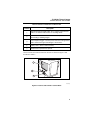
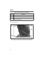
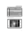
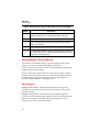
®
XS,
XST
IR InSight Thermal Imager
Users Manual
May 2006, Rev. 1, 8/06
© 2006 Fluke Corporation, All rights reserved.
All product names are trademarks of their respective companies.
LIMITED WARRANTY AND LIMITATION OF LIABILITY
Each Fluke product is warranted to be free from defects in material and workmanship
under normal use and service. The warranty period is two years and begins on the date of
shipment. Parts, product repairs, and services are warranted for 90 days. This warranty
extends only to the original buyer or end-user customer of a Fluke authorized reseller,
and does not apply to fuses, disposable batteries, or to any product which, in Fluke's
opinion, has been misused, altered, neglected, contaminated, or damaged by accident or
abnormal conditions of operation or handling. Fluke warrants that software will operate
substantially in accordance with its functional specifications for 90 days and that it has
been properly recorded on non-defective media. Fluke does not warrant that software will
be error free or operate without interruption.
Fluke authorized resellers shall extend this warranty on new and unused products to enduser customers only but have no authority to extend a greater or different warranty on
behalf of Fluke. Warranty support is available only if product is purchased through a Fluke
authorized sales outlet or Buyer has paid the applicable international price. Fluke reserves the right to invoice Buyer for importation costs of repair/replacement parts when
product purchased in one country is submitted for repair in another country.
Fluke's warranty obligation is limited, at Fluke's option, to refund of the purchase price,
free of charge repair, or replacement of a defective product which is returned to a Fluke
authorized service center within the warranty period.
To obtain warranty service, contact your nearest Fluke authorized service center to obtain
return authorization information, then send the product to that service center, with a description of the difficulty, postage and insurance prepaid (FOB Destination). Fluke assumes no risk for damage in transit. Following warranty repair, the product will be returned to Buyer, transportation prepaid (FOB Destination). If Fluke determines that failure
was caused by neglect, misuse, contamination, alteration, accident, or abnormal condition
of operation or handling, including overvoltage failures caused by use outside the product’s specified rating, or normal wear and tear of mechanical components, Fluke will provide an estimate of repair costs and obtain authorization before commencing the work.
Following repair, the product will be returned to the Buyer transportation prepaid and the
Buyer will be billed for the repair and return transportation charges (FOB Shipping Point).
THIS WARRANTY IS BUYER'S SOLE AND EXCLUSIVE REMEDY AND IS IN LIEU OF
ALL OTHER WARRANTIES, EXPRESS OR IMPLIED, INCLUDING BUT NOT LIMITED
TO ANY IMPLIED WARRANTY OF MERCHANTABILITY OR FITNESS FOR A PARTICULAR PURPOSE. FLUKE SHALL NOT BE LIABLE FOR ANY SPECIAL, INDIRECT,
INCIDENTAL OR CONSEQUENTIAL DAMAGES OR LOSSES, INCLUDING LOSS OF
DATA, ARISING FROM ANY CAUSE OR THEORY.
Since some countries or states do not allow limitation of the term of an implied warranty,
or exclusion or limitation of incidental or consequential damages, the limitations and exclusions of this warranty may not apply to every buyer. If any provision of this Warranty is
held invalid or unenforceable by a court or other decision-maker of competent jurisdiction,
such holding will not affect the validity or enforceability of any other provision.
Fluke Corporation
P.O. Box 9090
Everett, WA 98206-9090
U.S.A.
Fluke Europe B.V.
P.O. Box 1186
5602 BD Eindhoven
The Netherlands
11/99
To register your product online, visit register.fluke.com
Table of Contents
Title
Introduction............................................................................................
Contacting Fluke ....................................................................................
Safety Information .................................................................................
Unpacking Your Camera .......................................................................
Charge and Insert Battery ......................................................................
Power Camera On ..................................................................................
Select Palette Color................................................................................
Focus ......................................................................................................
Capture Image ........................................................................................
Camera Features and Controls ...............................................................
Using Display Screen Menus.................................................................
Menu Options.....................................................................................
SmartView Software for Your PC .........................................................
SmartView Software Installation Guide............................................
Powering the Camera On and Off .........................................................
Understanding the Internal Calibration Function ..................................
Focusing .................................................................................................
Changing Color Palettes ........................................................................
Changing Date and Time .......................................................................
Using External Video Output Devices ..................................................
Obtaining the Center Point Temperature...............................................
Setting Emissivity and Background Temperature .................................
Acquiring and Reviewing Images .........................................................
Scan Target ........................................................................................
Pause/Save .........................................................................................
Review Images...................................................................................
Saving and Naming an Image ............................................................
Connecting the Camera to a Computer..................................................
Using an RS-232 Port Connection.....................................................
Using a USB Port Connection ...........................................................
Downloading Images to a Computer .................................................
Deleting Images from Camera Memory ............................................
Camera Optics....................................................................................
Charging and Replacing the Battery......................................................
Using the Battery Charger .................................................................
i
Page
1
1
2
3
4
6
7
7
8
8
12
12
13
13
14
14
14
15
15
16
16
17
17
17
18
18
19
19
19
20
22
22
23
24
24
XS, XST
Users Manual
Inserting and Removing the Battery.................................................. 25
Camera Care ...................................................................................... 26
Appendices
A
Emissivity Values .................................................................. ...A-1
B
Camera Specifications and Dimensions ................................ ...B-1
Index
ii
List of Tables
Table
1.
2.
3.
4.
5.
6.
7.
A-1.
B-1.
Title
Standard Accessories .............................................................................
Features and Controls--Camera Front ...................................................
Features and Controls - Camera Back ...................................................
Display Screen Features and Controls--Scan Target Mode ..................
Display Screen Features and Controls--Review Image Mode ..............
Lens Field of View and Instantaneous Field of View ...........................
Battery Charging Status .........................................................................
Emissivity Values of Common Materials..............................................
Camera Specifications, IR InSight XS, XST.........................................
iii
Page
4
10
11
12
13
24
26
A-1
B-1
XS, XST
Users Manual
iv
List of Figures
Figure
1.
2.
3.
4.
5.
6.
7.
8.
9.
10.
11.
12.
B-1
Title
Standard Accessories .............................................................................
Charging the Battery ..............................................................................
Inserting the Charged Battery ................................................................
Powering the Camera On and Off .........................................................
Selecting Palette Color...........................................................................
Focusing the Camera..............................................................................
Features and Controls--Camera Front ...................................................
Features and Controls--Camera Back....................................................
Display Screen Features and Controls--Scan Target Mode ..................
Display Screen Features and Controls--Review Image Mode ..............
Charging the Battery ..............................................................................
Inserting the Charged Battery ................................................................
Camera Dimensions ...............................................................................
v
Page
3
5
5
6
7
7
9
10
11
12
25
26
B-3
XS, XST
Users Manual
vi
IR InSight Thermal Imager
Introduction
Thank you for choosing the IR InSight™ portable video-rate infrared imaging
camera (hereafter, “Camera”). Using the Camera, you can obtain instant and
accurate thermal images and radiometric readings from distant targets. This
Camera is ergonomically designed for right-hand or left-hand use, and captures
thermal images and data with a simple trigger press.
The Camera stores up to 255 images that can be downloaded to a personal
computer (PC). Using the SmartView™ companion PC software application,
you can examine, analyze, enhance, and archive your images and data.
Your Camera provides high performance thermal imaging and is designed for
building diagnostics and entry level predictive maintenance.
The IR InSight:
•
Has ease of use “point and shoot’ single trigger operation.
•
Delivers industry leading image quality.
•
Has rugged tool-like durable housing.
•
Has large 3.5 inch display.
Contacting Fluke
To contact Fluke, call:
1-888-993-5853 in USA
1-800-363-5853 in Canada
+31-402-675-200 in Europe
+81-3-3434-0181 in Japan
+65-738-5655 in Singapore
+1-425-446-5500 from anywhere in the world
Or, visit Fluke’s Web site at www.fluke.com
1
XS, XST
Users Manual
To register your product, visit register.fluke.com
For Thermography related questions, contact Fluke at 1.800.760.4523 in USA
Safety Information
Use your Camera only as specified in this manual.
A WWarning identifies hazardous conditions and actions that could cause
bodily harm or death.
A WCaution identifies conditions and actions that could damage the camera
or cause permanent loss of data.
WCaution
•
Your infrared Camera is a precision instrument that uses a
sensitive infrared (IR) detector. Pointing your Camera
towards highly-intense energy sources—including devices
that emit laser radiation and reflections from these
devices—may adversely affect Camera accuracy and may
harm or permanently damage your Camera’s IR detector.
•
Your Camera was calibrated prior to shipping. We
recommend that you have your camera checked for proper
calibration every two years. Some ISO 9000 programs
require more frequent checks for certification. Contact
Fluke for details.
•
Your Camera requires five minutes to warm up before
achieving the most accurate measurements.
•
Do not use Camera in a manner not specified in this
manual or the protection provided by the equipment may
be impaired.
r n Note
This camera contains a Nickel-Cadmium battery.
Do not mix with the solid waste stream. Spent batteries should be
disposed of by a qualified recycler or hazardous materials handler.
Contact your authorized Fluke Service Center for recycling
information.
2
IR InSight Thermal Imager
Unpacking Your Camera
Unpacking Your Camera
Begin by opening the shipping box. Be sure to save the box and shipping
materials in case you need to ship the Camera. Inside the shipping box, you
will find a hard carrying case containing the standard accessories shown in
Figure 1 and described in Table 1.
eiw001.eps
Figure 1. Standard Accessories
3
XS, XST
Users Manual
Table 1. Standard Accessories
A
B
Camera with Battery
RS-232 Communications
Cable & USB Adapter
C
Shoulder and Neck Strap
D
XS, XST Getting Started
Guide
E
Extra Battery
F
SmartView Software,
XS, XST IR InSight Users
Manual, and USB drivers
CD-ROM disks
G
Battery Charger
Charge and Insert Battery
Note
The battery fits into the charger and the Camera only one way.
Charge a new battery as shown in Figure 2 for 24 hours; thereafter, a
completely discharged battery requires 30 minutes to charge. Use only the
rechargeable battery supplied. A battery is fully charged when the LED light
on the charger is flashing green.
Insert the charged battery into the bottom of the camera as shown in
Figure 3.
4
IR InSight Thermal Imager
Charge and Insert Battery
eiw002.eps
Figure 2. Charging the Battery
eiw003.eps
Figure 3. Inserting the Charged Battery
5
XS, XST
Users Manual
Power Camera On
With a charged battery inserted, toggle the ON/OFF switch to the right as
shown in Figure 4.
eiw004.eps
Figure 4. Powering the Camera On and Off
Note
After powering on the Camera, it requires a boot up and warm up
period of approximately 30 seconds in order to maintain a crisp,
clear, real-time image. About five minutes after powering on the
camera, the temperature measurement accuracy will be within the
specification requirements. The start-up screen appears after
approximately 10 seconds.
6
IR InSight Thermal Imager
Select Palette Color
Select Palette Color
Toggle the ON/OFF switch to either of two on positions, I or II depending on
which palette you want, as shown in Figure 5. See Changing Color Palettes in
later in this manual for additional palette options.
eiw005.eps
Figure 5. Selecting Palette Color
Focus
Remove the lens cap, point the lens at the target, and manually rotate the lens
with your finger, as shown in Figure 6 until the image is in focus.
eiw006.eps
Figure 6. Focusing the Camera
7
XS, XST
Users Manual
Capture Image
Pull and release the Frame Capture Trigger. The image on the screen freezes
for approximately 2-3 seconds and is saved to the Camera internal memory.
To retain the saved image on the display screen for further review, do not
release the Frame Capture Trigger when capturing the image. The Camera
automatically returns to the Scan Target mode once you release the Frame
Capture Trigger.
Camera Features and Controls
Features and controls found on the front of the Camera are shown in Figure 7
and described in Table 2.
eiw007.eps
Figure 7. Features and Controls--Camera Front
8
IR InSight Thermal Imager
Camera Features and Controls
Table 2. Features and Controls--Camera Front
Description
Number
A
Standard Composite NTSC Video Port—Used to output infrared
video to an external video monitor or recording device.
B
RS-232 Port—Used to connect camera to a computer for
downloading or deleting images.
C
Frame Capture Trigger—Used to pause and save an image frame
and to advance through saved images or menu items.
D
Battery Latch—Pinch to release battery.
E
Attachment for optional laser pointer.
Camera features and controls found on the back are shown in Figure 8 and
described in Table 3.
1
2
3
eiw008.eps
Figure 8. Features and Controls--Camera Back
9
XS, XST
Users Manual
Table 3. Features and Controls - Camera Back
Number
Description
A
3 1/2” Liquid Crystal Display (LCD) Screen
B
Camera Lanyard Bracket
C
ON/OFF Switch—Used to power camera on and off and to select
desired color palette option.
Display screen features and controls for scan target mode are shown in Figure
1-9 and described in Table 4.
6
1
2
5
3
4
eiw009.eps
Figure 9. Display Screen Features and Controls--Scan Target Mode
10
IR InSight Thermal Imager
Camera Features and Controls
Table 4. Display Screen Features and Controls--Scan Target Mode
Number
Description
A
Center Point Temperature—Shows the average temperature in
degrees Fahrenheit of four central pixels (XST model only).
B
Palette Bar—Shows the palette colors or gray shades from coldest
to hottest temperature.
C
Center Point—Includes the center 2 X 2 pixels (XST model only).
D
Date—Displays the current month, day, and year.
E
Time—Displays the current time (24-hour clock).
F
Saved Image Numbers—Indicates the number of images saved to
the camera memory. Memory holds up to 255 images.
Display screen features and controls for review image mode are shown in
Figure 10 and described in Table 5.
5
1
2
4
3
eiw010.eps
Figure 10. Display Screen Features and Controls--Review Image Mode
11
XS, XST
Users Manual
Table 5. Display Screen Features and Controls--Review Image Mode
Number
Description
A
Center Point Temperature—Shows the average temperature in
degrees Fahrenheit of four central pixels (XST model only).
B
Center Point—Includes the center 2 X 2 pixels (XST model only).
C
Date—Indicates the year, month, day, and day of the week an
image was captured.
D
Time—Indicates the time (24-hour clock) an image was captured.
E
Saved Image ID Numbers—Indicates the identification number of
the saved image you are reviewing and the total number of saved
images in the camera memory.
Using Display Screen Menus
Your camera is user-friendly and easy to operate using the Frame Capture
Trigger to access and navigate through display screen menus.
To access the main menu, start the Camera while simultaneously pulling and
holding the Frame Capture Trigger.
From the main menu, pull and release the Frame Capture Trigger to advance
through the list of menu options until you reach the desired function. Release
the Frame Capture Trigger for 4 seconds to select the desired function; a
4-second countdown appears on the display screen.
Menu Options
Highlight “Run Normally” and release the Frame Capture Trigger for 4
seconds to access Scan Target mode. See Acquiring and Reviewing Images
later in this manual.
Highlight “Change Palette” and release the Frame Capture Trigger for 4
seconds to access a submenu listing 10 palette options. The palette bar for the
palette chosen is shown on the right of the Camera display screen. See
Changing Color Palettes later in this manual.
12
IR InSight Thermal Imager
SmartView Software for Your PC
Highlight “Review Images” and release the Frame Capture Trigger for 4
seconds to access Review Image mode. If there are no saved images, “Review
Images” does not appear in the main menu list. See Acquiring and Reviewing
Images later in this manual.
Highlight “Erase All Images” and release the Frame Capture Trigger for 4
seconds to erase all images at once. If there are no saved images, “Erase All
Images” does not appear in the main menu list. See Deleting Images from
Camera Memory later in this manual.
SmartView Software for Your PC
Your system includes a CD containing SmartView™ software that you install
on your personal computer (PC). SmartView, together with your Camera,
enables you to:
•
Transfer thermographic images to a computer and efficiently manage
them
•
Optimize and analyze your infrared and visible light control images
•
Create and print detailed, professional reports containing important
image data
SmartView Software Installation Guide
SmartView image analysis software is compatible with a PC running
Microsoft® Windows™ 98/ME/2000/XP. This software is provided on the
SmartView CD-ROM disk included with your Camera.
To install SmartView software on your computer:
1.
Start your computer and close any open applications.
2.
Insert the CD-ROM disk containing the SmartView software in the
CD-ROM drive.
If the SmartView CD does not start automatically, use Windows
explorer to locate the file named "launch.exe" on the CD-ROM. Start
the CD by double-clicking the "launch.exe" file. You can also install
SmartView by using the "setup.exe" which is also on the CD-ROM.
3.
Follow the on-screen instructions to complete the installation.
13
XS, XST
Users Manual
Powering the Camera On and Off
Note
After powering on the Camera, it requires a boot up and warm up
period of approximately 30 seconds in order to maintain a crisp,
clear, real-time image. Approximately five minutes after powering on
the camera, the temperature measurement accuracy will be within the
specification requirements. The start-up screen appears after
approximately 10 seconds.
Insert a charged battery. See Charging and Replacing the Battery later in this
manual.
To start the Camera in Scan Target mode, toggle the ON/OFF switch to the
right.
To access the main menu upon start up, toggle the ON/OFF switch to the right,
while simultaneously pulling and holding the Frame Capture Trigger.
To power the camera off, toggle the ON/OFF switch to the left.
Understanding the Internal Calibration
Function
Your Camera has an internal calibration function that automatically adjusts the
camera electronics as needed to maintain a high quality image. During an
internal calibration, you may hear a faint “double click” sound from the
camera and see the word “Calibrating” appear on the display screen. The
image is frozen for approximately 1-2 seconds during the internal calibration
process.
Focusing
Your Camera has a manual lens/image focus. To focus the camera, remove the
lens cap, point the lens at the target, and manually rotate the lens focus ring
with your finger until the image is in focus.
14
IR InSight Thermal Imager
Changing Color Palettes
Changing Color Palettes
You can switch between two of ten palettes by toggling the ON/OFF switch
between the two on positions, “I” and “II.”
To change one or both selected palettes:
1.
Start the Camera by toggling the ON/OFF switch to the right, while
simultaneously pulling and holding the Frame Capture Trigger. This
opens the main menu.
2.
Toggle the ON/OFF switch to either on position “I” or “II,”
depending on which palette you want to change.
3.
Advance the main menu option by pulling and releasing the Frame
Capture Trigger until “Change Palette” is highlighted, and then
release the Frame Capture Trigger for 4 seconds.
4.
Advance the submenu option by pulling and releasing the Frame
Capture Trigger to highlight the desired palette, and then release the
Frame Capture Trigger for 4 seconds to activate the palette change
and return to the main menu. Maintain the Frame Capture Trigger
release for another 4 seconds to return to Scan Target mode or go to
Step 5 to change the second selected palette.
5.
To change the second palette, toggle the ON/OFF switch to either on
position “I” or “II,” depending on which palette you want to change
and repeat Steps 3 and 4.
Changing Date and Time
Your Camera has an internal calendar and clock. The date and time are
recorded within the image file when the image is saved. Using the SmartView
PC software provided with the Camera, you can update the time and date of
the Camera to the time and date in your PC.
Follow the appropriate procedure under Connecting Camera to a Computer
found later in this manual. If the Camera clock and calendar do not match
within 10 minutes of the PC clock and calendar, a pop-up window appears
asking if you want to set the Camera clock and calendar to match the PC. If
you select “Yes,” the Camera time and calendar change to match the PC. If
you select “No,” the Camera time and calendar remain unchanged.
15
XS, XST
Users Manual
Using External Video Output Devices
Using the video port and video cable, you can display the live, paused, or
saved images on a TV, video projector, or video monitor. You can also record
images on a video recorder. Video output is National Television Standards
Committee (NTSC) format.
To view images on or record images to an external device, plug the end of the
video cable with the cylindrical noise suppressor into the Camera video port.
Plug the other end of the cable into the TV, projector, monitor, or video
recorder.
Obtaining the Center Point Temperature
Note
For most accurate measurements allow your camera to warm up for
five minutes.
The center 4 pixels on your Camera display screen are calibrated to output a
single average temperature referred to as the center point temperature. This
reading assumes the target emissivity is 0.95 and the background temperature
is20 °C (68 °F). Many common target materials, such as painted surfaces,
human skin, water, electrical wire insulation, wood, and most types of tape,
have an emissivity value of approximately 0.95. See Appendix A for the
emissivity values of other common materials.
If the target object’s emissivity value is something other than 0.95 and/or the
ambient temperature is significantly higher or lower than, 20 °C (68 °F), then
the center point temperature becomes a relative temperature only. See Setting
Emissivity and Background Temperature later in this Manual.
Your Camera is calibrated to operate at ambient temperatures from
0 °C to 50 °C (32 °F to 122 °F) and to display an accurate center point
temperature (within 2 ºC or 2 % of the reading, which ever is largest) when
used within this ambient temperature range.
For ambient temperatures outside the 0 °C to 50 °C (32 °F to 122 °F) range,
the measurement accuracy may degrade, but is generally within 5 °C or 5 % of
the target temperature.
When the Camera is abruptly moved from one ambient temperature to another,
it requires about five minutes per 10 °C ambient temperature change to adjust
16
IR InSight Thermal Imager
Setting Emissivity and Background Temperature
to the new ambient temperature before the temperature measurement meets the
accuracy specification.
Setting Emissivity and Background
Temperature
Emissivity and background temperature are fixed on the Camera. However,
they can be adjusted to other values to obtain accurate temperatures of targets
that have emissivity other than 0.95 and/or a background temperature different
from 20 °C (68 °F).
Using a PC installed with the SmartView software application, download the
images following the procedure under Downloading Images to a Computer
found later in this Manual. Then, in SmartView, highlight the desired image,
click on the emissivity value or background temperature value, and enter the
desired value. See the SmartView online help for more details.
Acquiring and Reviewing Images
Your Camera has three operating modes: Scan Target, Pause/Save, and
Review Images.
Scan Target
To scan target area of interest:
1.
Toggle the ON/OFF switch to the right; DO NOT pull the Frame
Capture Trigger while the Camera is booting up.
2.
Remove the lens cap and point the lens at the target area.
3.
Focus and view the target area on the display screen.
4.
Move the Camera as necessary to view various scenes.
17
XS, XST
Users Manual
Pause/Save
To pause and save a target area image:
1.
Follow the procedure under Scan Target.
2.
When an area of interest is visible on the display screen, pull and
release the Frame Capture Trigger. The image on the screen freezes
for approximately 2-3 seconds and is saved to the Camera internal
memory. The image ID number and number of saved images in the
camera memory is displayed in the upper left corner of the display
screen. See Naming Image Files later in this Manual.
To retain the saved image on the display screen for further review, do not
release the Frame Capture Trigger when capturing the image. The Camera
automatically returns to the Scan Target mode once you release the Frame
Capture Trigger.
Review Images
To view images saved to the Camera’s internal memory:
Note
Review Images mode must be started from the main menu. If there are
no saved images, “Review Images” does not appear in the main menu
and the Camera will start in Scan Target mode after releasing the
Frame Capture Trigger for 4 seconds with “Run Normally”
highlighted.
18
1.
If the Camera is ON, toggle the ON/OFF switch to the left to power
the Camera off.
2.
If the Camera is OFF, power the Camera on by toggling the ON/OFF
switch to the right, while simultaneously pulling and holding the
Frame Capture Trigger. This opens the main menu.
3.
From the main menu, pull and release the Frame Capture Trigger to
highlight “Review Images,” and then release the Frame Capture
Trigger for 4 seconds.
4.
View each saved image one at a time by repeatedly pulling and
releasing the Frame Capture Trigger. The images are displayed
beginning with the most recent image saved.
IR InSight Thermal Imager
Connecting the Camera to a Computer
5.
Return to the main menu by pulling and holding the Frame Capture
Trigger for 3 seconds.
6.
Return to Scan Target mode by highlighting “Run Normally” from
the main menu, then releasing the Frame Capture Trigger for 4
seconds.
Saving and Naming an Image
Whenever an image is saved, the image ID number is increased progressively
from 1 to 255. The image file name, when first saved, consists of a four
character year, a two character month, a two character day, a week day, a two
character hour, a two character minute, a two character second, and a three
digit image ID number.
You can rename the file using SmartView installed on a personal computer.
However, the original time and date stamp imbedded in the image file remains
unchanged.
Connecting the Camera to a Computer
You can connect your Camera to a personal computer (PC) installed with
SmartView™ software and transfer images saved in the Camera’s memory to
the PC. Then, use SmartView to add annotations, references, and comments to
your InSight images, as well as change image color palettes and rename,
analyze, organize, and print images.
Note
If the PC you are using has both RS-232 and USB options, connect
the Camera to the PC using the RS-232 port and cable. If the PC has
only a USB port, use a combination of the RS-232/USB cable and
RS-232 cable. The procedures for both options are described on the
following pages.
Using an RS-232 Port Connection
To connect the Camera to a PC using the PC RS-232 port:
1.
Connect the RS-232 cable to the PC and Camera.
2.
Be sure SmartView is installed on your PC then open the application.
19
XS, XST
Users Manual
3.
Configure SmartView to use the proper communications port:
•
Click “Edit” on the SmartView Menu Bar, then click
“Preferences…,” then click the InSight Settings tab.
•
Select the appropriate default communications port and click
“OK.”
Note
The following instructions are for Microsoft Windows XP. If you are
using a different version, check the users manual that came with your
Windows operating system.
4.
•
If you are unsure which communications port to select, access the
PC device manager on the PC desktop. Right click on the “My
Computer” icon and select “Properties.” Go to the “Hardware”
tab and select “Device Manager.” A “Device Manager” window
will appear. Left click on the “+” sign next to the word “Ports.”
The actual port number may depend on the devices currently in
use on the PC.
•
When prompted to use these settings in future sessions, select
“Yes”.
Toggle the ON/OFF switch to the right to power the camera on.
•
5.
If the Camera clock and calendar do not match within 10 minutes
of the PC clock and calendar, a pop-up window appears asking if
you want to set the Camera clock to match the PC. If you select
“Yes,” the Camera time and calendar change to match the PC. If
you select “No,” the Camera time and calendar remain
unchanged.
The Camera is now connected to the PC and ready to download
images. See procedure under Downloading Images to Computer later
in this manual.
Using a USB Port Connection
To connect the Camera to a PC using the USB port:
1.
20
Connect the RS-232/USB cable to the USB communications port on
the PC. Do not power on the Camera.
IR InSight Thermal Imager
Connecting the Camera to a Computer
2.
Place the USB Serial Converter Product Driver CD-ROM disk into
the PC’s CD-ROM drive.
3.
Follow the directions of the USB Serial Converter User Manual to
install the driver software for your PC and operating system.
4.
Be sure SmartView is installed on your PC then open the application.
5.
Configure SmartView to use the proper communications port:
•
Click “Edit” on the SmartView Menu Bar, then click
“Preferences…,” then click the InSight Settings tab.
•
Select the appropriate default communications port and click
“OK.”
Note
The following instructions are for Microsoft Windows XP. If you are
using a different version, check the users manual that came with your
Windows operating system.
•
If you are unsure which communications port to select, access the
PC device manager on the PC desktop. Right click on the “My
Computer” icon and select “Properties.” Go to the “Hardware”
tab and select “Device Manager.” A “Device Manager” window
will appear. Left click on the “+” sign next to the word “Ports.”
The actual port number may depend on the devices currently in
use on the PC.
•
When prompted to use these settings in future sessions, select
“Yes.”
6.
Connect one end of the RS-232 cable to the Camera and the other end
to the end of the RS-232/USB cable already connected to the USB
communications port on the PC.
7.
Toggle the Camera’s ON/OFF switch to the right to power the
Camera on.
8.
If the Camera clock and calendar do not match within 10 minutes of
the PC clock and calendar, a pop-up window appears asking if you
want to set the Camera clock to match the PC. If you select “Yes,” the
Camera time and calendar change to match the PC. If you select
“No,” the Camera time and calendar remain unchanged.
21
XS, XST
Users Manual
9.
The camera is now connected to the PC and is ready to download
images. See procedure under Downloading Images to a Computer
later in this manual.
Downloading Images to a Computer
To download images from the Camera to a PC:
1.
Connect the Camera to the PC using either the PC RS-232 or USB
port as described earlier in this manual. Power on both the Camera
and PC.
2.
Open the SmartView application on the PC, and then click “File” on
the SmartView Menu Bar.
3.
Click “Download Images,” then click “InSight Images.” A directory
dialog appears to retrieve a file path.
4.
In the “Browse for Folder” pop-up window, choose the folder in
which you want to store the images.
5.
Click “OK” to start the download process. A pop-up window appears
indicating the number of images being downloaded. As the image
files are downloaded, the download progress is displayed.
6.
Once all image files are downloaded, a pop-up window appears,
indicates “Download Complete,” and asks if you want to clear the
images from the Camera memory.
•
Click “No” to keep saved images in the Camera memory.
•
Click “Yes” to delete ALL images from the Camera memory. A
pop-up window appears indicating “Image Memory Cleared.”
Click “OK.” See also, Deleting Saved Images later in this
Manual.
Deleting Images from Camera Memory
You can delete images saved in the Camera memory either using SmartView
software or from the Camera’s main menu.
22
IR InSight Thermal Imager
Connecting the Camera to a Computer
WCaution
To prevent image loss, be sure to transfer the images
saved on the Camera internal memory to a computer hard
drive and/or other back up storage device (e.g., CD-R disc)
before deleting images.
To delete all saved images from the Camera using SmartView, follow the
procedure under Downloading Images to a Computer earlier in this manual.
or
To delete all saved images using the Camera’s main menu:
1.
Start the Camera by toggling the ON/OFF switch to the right while
simultaneously pulling and holding the Frame Capture Trigger. This
opens the main menu.
2.
From the main menu, pull and release the Frame Capture Trigger to
highlight “Erase All Images,” and then release the Frame Capture
Trigger for 4 seconds.
3.
“Are You Sure” appears. Highlight “Yes,” and release the Frame
Capture Trigger for 4 seconds to delete all images.
Camera Optics
Your Camera comes with an f 0.8 20 mm focal length lens. The lens is made
of Germanium crystal and is antireflection coated for high transmission in the
8 to 14 micron wavelength band.
The field of view (FOV), instantaneous field of view (IFOV) and spot size
ratio for the Camera is listed in Table 6.
Table 6. Lens Field of View, Instantaneous Field of View and Spot Size
Lens Focal Length
20 (mm)
Image IFOV
0.146 (degrees)
Horizontal FOV
23.2 (degrees)
Image IFOV
2.55 (mrad)
Vertical FOV
17.4 (degrees)
Image Spot Size
392 to 1
Center Point Spot
Size
196 to 1
Center Point IFOV
5.10 (mrad)
23
XS, XST
Users Manual
Charging and Replacing the Battery
Your Camera is powered by a 12 V rechargeable Nickel-Cadmium (Ni-Cd)
battery pack. When fully charged, the battery provides approximately 3 hours
of continuous power. Battery charger use is shown in Figure 11 and battery
placement in Figure 12.
Using the Battery Charger
Note
To maximize battery performance and life, charge a new battery for
24 hours the first time. Thereafter, a completely discharged battery
takes approximately 30 minutes to charge.
1.
Connect the battery charger AC power supply to a power outlet. An
outlet adapter and voltage converter may be necessary outside of the
United States.
2.
Connect the power supply to the battery charger.
3.
Insert the battery as shown in Figure 11; the battery fits only one way.
The LED indicator on the charger indicates the charging status as shown in
Table 7.
eiw002.eps
Figure 11. Charging the Battery
24
IR InSight Thermal Imager
Charging and Replacing the Battery
Table 7. Battery Charging Status
Indicator
Charging Status
Red Flashing
Charger is connected to AC outlet and ready for use.
Red Solid
Battery charging underway.
Green Flashing
Battery charging complete.
Orange Solid
Battery pack is warm; charging will begin when battery
pack temperature drops.
Orange Flashing
Charging not possible. Battery and/or charger terminals
may be dirty or the battery pack is malfunctioning.
Inserting and Removing the Battery
To insert the battery, align the battery with the Camera handle shown in Figure
12. Firmly press the battery into the handle until it latches; the battery fits one
way.
To remove the battery from the Camera, hold the Camera upright. Squeeze the
battery latch with the other hand and pull the battery away from the handle.
eiw003.eps
Figure 12. Inserting the Charged Battery
25
XS, XST
Users Manual
Camera Care
For optimal performance, your Camera should be treated with care and gently
cleaned as needed. You should always take great care whenever you touch the
lens or display screen. The lens elements are made from Germanium crystal
and easily can shatter or be scratched and chipped. The liquid crystal display
(LCD) screen is sensitive to excess pressure. To protect your Camera, replace
the lens cap and store the camera in the case when you are not using it.
WCaution
To avoid damaging your camera, use compressed air to
remove large particles and dust prior to using a cloth.
To clean the lens:
•
Lightly rub the lens with a soft cotton cloth slightly moistened (not
dripping) with a non-abrasive solution marked for lens cleaning or a
mild, diluted dish soap solution (never use solvents).
To clean the display screen:
•
Lightly rub the display screen with a clean computer monitor cleaning
cloth.
To clean the camera body:
•
26
Lightly rub the camera body with a clean, slightly damp cloth.
Dampen the cloth in a solution of water and a small amount of mild
soap if needed.
Appendices
Appendix
Title
Page
Emissivity Values................................................................................................ A-1
Camera Specifications and Dimensions.............................................................. B-1
XS, XST
Users Manual
Appendix A
Emissivity Values
Use the emissivity values shown in Table A-1 as a guide to properly setting the
emissivity value on your Camera.
Table A-1. Emissivity Values of Common Materials
Material
Temperature (°C)
Emissivity
Aluminum, polished
0
0.05
Aluminum, rough
surface
0
0.07
Aluminum, strongly
oxidized
0
0.25
Asbestos board
0
0.96
Asbestos fabric
0
0.78
Asbestos paper
0
0.94
Asbestos slate
0
0.96
Brass, dull, tarnished
0
0.22
Brass, polished
0
0.03
Brick, common
0
0.85
Brick, glazed, rough
0
0.85
Brick, refractory, rough
0
0.94
Bronze, porous, rough
0
0.55
Bronze, polished
0
0.10
A-1
XS, XST
Users Manual
Table A-1. Emissivity Values of Common Materials (cont.)
Material
Temperature (°C)
Emissivity
Carbon, purified
0
0.80
Cast iron, rough casting
0
0.81
Cast iron, polished
0
0.21
Charcoal, powdered
0
0.96
Chromium, polished
0
0.10
Clay, fired
0
0.91
Concrete
0
0.54
Copper, polished,
annealed
0-17
0.01-0.02
Copper, commercial
burnished
0
0.07
Copper, oxidized
0
0.65
Copper, oxidized to
black
0
0.88
Electrical tape, black
plastic
0
0.95
Enamel
27
0.90
Formica
0
0.93
Frozen soil
0
0.93
Glass
0
0.92
Glass, frosted
0
0.96
Gold, polished
0
0.02
Ice
0
0.97
Iron, hot rolled
0
0.77
Iron, oxidized
0
0.74
A-2
Appendices
Emissivity Values
A
Table A-1. Emissivity Values of Common Materials (cont.)
Material
Temperature (°C)
Emissivity
Iron, sheet galvanized,
burnished
0
0.23
Iron, sheet, galvanized,
oxidized
0
0.28
Iron, shiny, etched
0
0.16
Iron, wrought, polished
0
0.28
Lacquer, Bakelite
0
0.93
Lacquer, black, dull
0
0.97
Lacquer, black, shiny
0
0.87
Lacquer, white
0
0.87
Lampblack
0
0.96
Lead, gray
0
0.28
Lead, oxidized
0
0.63
Lead, red, powdered
0
0.93
Lead, shiny
0
0.08
Mercury, pure
0
0.10
Nickel, on cast iron
0
0.05
Nickel, pure polished
0
0.05
Paint, silver finish
25
0.31
Paint, oil, average
0
0.94
Paper, black, shiny
0
0.90
Paper, black, dull
0
0.94
Paper, white
0
0.90
Platinum, pure, polished
0
0.08
Porcelain, glazed
0
0.92
A-3
XS, XST
Users Manual
Table A-1. Emissivity Values of Common Materials (cont.)
Material
Temperature (°C)
Emissivity
Quartz
0
0.93
Rubber
0
0.93
Shellac, black, dull
0
0.91
Shellac, black, shiny
0
0.82
Snow
0
0.80
Steel, galvanized
0
0.28
Steel, oxidized strongly
0
0.88
Steel, rolled freshly
0
0.24
Steel, rough surface
0
0.96
Steel, rusty red
0
0.69
Steel, sheet, nickelplated
0
0.11
Steel, sheet, rolled
0
0.56
Tar paper
0
0.92
Tin, burnished
0
0.05
Tungsten
0
0.05
Water
0
0.98
Zinc, sheet
0
0.20
A-4
Appendix B
Camera Specifications and
Dimensions
Table B-1 lists the technical specifications for the IR InSight XS and XST
camera models.
Table B-1. Camera Specifications, IR InSight XS, XST
Imaging Performance
Detector Type
Uncooled Microbolometer (160 by
120 Focal Plane Array)
Detector Size
51 µm Square
Spectral Band
8 µm to 12 µm
Thermal Sensitivity @ 30 Hz
< 0.07 °C at 30 °C
Video Frame Rate
30 Hz
Display and Image Storage
Digital Display
3 1/2 in LCD
On-screen Indicators
Date, time and saved image numbers,
Center point and center point
temperature on XST version only
Palettes
10 grayscale and color
Storage Medium
Internal Flash memory with 255
image capacity
PC File Formats Supported
JPEG, TIFF and BMP
B-1
XS, XST
Users Manual
Table B-1. Camera Specifications, IR InSight XS, XST
Temperature Measurement (for XST Version Only)
Calibration Temperature Range
0 °C to 100 °C (32 °F to 212 °F)
Accuracy
± 2 °C or ± 2 % for targets with 0.95
emissivity and background
temperature of 20 °C (68 °F)
Measurement Modes
Center point only
Emissivity and Ambient Temperature
Correction
Emissivity fixed at 0.95 and
background temperature at 20 °C
(68 ° F) on camera, both can be
changed on PC with analysis
software, SmartView, provided with
camera
Optics
Standard Lens
Germanium 20 mm f/0.8; 23 °
Horizontal x 17° Vertical FOV and
2.6 mrad IFOV
Optional Lenses
Germanium 10.5 mm f/0.8 and 54 mm
f/1.0
Focus
Manual
Power
Battery Type
Field-replaceable 12-V NiCd
Battery Operating Time
3 hours continuous operation
Battery Charging
120 V, 60 Hz
Interfaces
Image Transfer
Via RS-232 connection to PC with
supplied software, USB converter
included
Video Output
RS170 EIA/NTSC composite video
B-2
Appendices
Camera Specifications and Dimensions
B
Table B-1. Camera Specifications, IR InSight XS, XST
Physical Characteristics
Weight (with battery)
1.86 kg (4.12 lbs)
Size
12.7 cm x 8.89 cm x 27.94 cm
(5 in x 3.5 in x 11 in)
Environmental
Operating Temperature
-10 °C to +50 °C (14 °F to 122 °F)
Storage Temperature
-40 °C to +70 °C (-40 °F to 158 °F)
Humidity
Operating and storage 10 % to 95 %,
non-condensing
Camera dimensions are shown in Figures B-1.
5”
5.1”
11.3”
eiw011.eps
Figure B-1. Camera Dimensions
B-3
XS, XST
Users Manual
B-4
Index
—A—
accessories, 3
acquiring images, 17
—B—
background temperature
setting, 17
batteries
charging, 24
disposal, 2
inserting, 25
—C—
calibration temperature range, 2
camera features and controls
back, 9
front, 8
camera memory
delete images from, 22
save images XE "pause image mode"
to, 18
camera optics
field of view, 23
instantaneous field of view, 23
spot size, 23
camera specifications, 1
capture image, 8, See save image mode
center point temperature, 16
charging batteries, 24
cleaning
camera body, 26
display screen, 26
lens, 26
color palette
changing, 15
communication port
configuring RS-232, 19
configuring USB, 20
computer
connecting camera to, 19
downloading images to, 22
smartview software, 13
connecting camera to computer, 19
contacting Fluke, 1
—D—
date
changing, 15
delete images, 22
display screen
menu options, 12
review image mode, 11
scan target mode, 10
download images, 22
—E—
emissivity
setting, 17
values table, 1
erase all images, 22
external video output, 16
—F—
features and controls
camera back, 9
camera front, 8
field of view (FOV), 23
file naming, 19
Fluke
contact, 1
focus, 7, 14
1
XS, XST
Users Manual
frame capture trigger, 9
—I—
image
file naming, 19
pause, 18
save, 18
image name, 19
instantaneous field of view (IFOV), 23
internal calibration, 14
—M—
main menu
access, 12
options, 12
menus, 12
display screen options, 12
—N—
naming image files, 19
changing, 19
—O—
off switch, 10
on switch, 10
on positions I, II, 7
reviewing images, 17
RS-232 port, 19
—S—
safety information, 2
save image mode
delete all saved images, 22
review saved image, 18
scan target mode, 17
smartview software, 13
specifications, 1
spot size, 23
—T—
technical support, 1
temperature
center point, 16
temperature range. See calibration
temperature range
time
changing, 15
transfer images, 22
—U—
unpack camera, 3
USB port, 20
—P—
—V—
palette
changing, 15
pause image mode, 18
PC. See personal computer
personal computer
connect camera, 19
download images to, 22
power camera
off, 14
on, 14
video
external devices, 16
—R—
review image mode, 18
2
—W—
warranty, ii