1
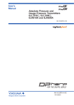
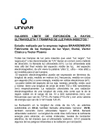
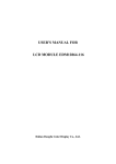
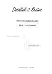
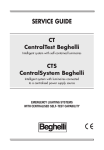
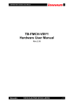
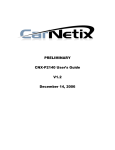
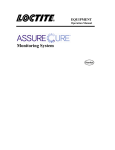
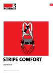
ST Series POWER SUPPLIES
USER INSTRUCTIONS
Introduction
These instructions detail the installation and operation requirements for the ST20 & ST35 power
supplies. These have been designed for operation in RV’s providing a DC power system, with
optional battery back up.
The units operate from 240Vac and provide an isolated 13.65Vdc output at 20A and 35A
respectively for powering the load and charging of batteries. All the necessary protection and
operating features for the load and batteries are provided. An optional DC input is also provided to
enable charging of batteries and powering of the load from an external +13.8V dc power source.
The units are fully enclosed ready for direct wall mounting. All connections are at the rear of unit
providing convenient wiring and installation. User access to all load and battery fusing has been
provided from the front of the unit.
Operation
Safety: Refer to the installation section before operating. Correct installation is the most critical
factor in ensuring the safe use of the power supply. If every consideration of these instructions has
been satisfied the power supply will be safe to operate.
Functional Diagram:
Fuse Panel
DC External
Input
+ve
AC / DC
Power Supply
5 x Load
Outputs
-ve
AC Input
Vadj
Isense
Battery Low Voltage
Disconnect circuit
1.2A
Trickle
+ve
Battery
Output
-ve
Figure 1 Functional Block Diagram
AC/DC Power Supply: This provides an isolated 13.65Vdc output for powering of the load and
float charging of the battery. Battery current is sensed and monitored by the power supply to ensure
that the maximum charging current is not exceeded.
Battery Features: The power supply provides automatic battery operation of the following.
Charging current is limited to a maximum of 5A (ST20) and 10A (ST35). This provides optimum
life for the batteries.
To charge at the maximum battery charge current above, ensure the load current plus battery current
is equal or less than the maximum output current. The charging current will be reduced in situations
Page 1 of 7
7982
ST Series POWER SUPPLIES
USER INSTRUCTIONS
were the difference between the rated output current and the load current (the available charging
current), is less than the maximum charging current.
Also note that the battery current sense is provided in the “-ve” battery output. For this feature to
work, the load and battery “-ve” should not be cross connected. (Appliances connected to the
chassis must also be taken into consideration. ie if the battery is connected to the chassis, then
cannot have an appliance with its “–ve” connected to the chassis)
Low Voltage Disconnection of the batteries is provided to prevent deep discharge of the battery.
Automatic reconnection occurs when battery voltage recovers.
Battery Current Drain is always present. The battery should be isolated if the unit is not in regular
use. See specifications for details.
Trickle Charge to the battery is always present. When the battery voltage is below the LVD reconnect voltage (<9V) and the mains power is available, the battery will be charging at 1.2A. When
the battery voltage sufficient (>9V) the LVD will connect the battery and allow float charging at
5A/10A (ST20/ST35). This feature is provided to allow “very” flat batteries to be charged at a rate,
which will extend their life.
External Input Voltage: This provides an alternative option for powering of the load and float
charging of the batteries when mains voltages are not present. This input is to be powered by a
suitable +12V system. (ie CAR or SOLAR cells with regulator).
When operating via the external input, current and voltage control for the battery must be provided
from the external source. The ST20/35 does not provide battery current limit or voltage control
when operating in this configuration.
Suitable fuse protection must be provided for this input.
Protection: the power supply provides automatic protection for overload including short circuit,
over-voltage, over-temperature and reverse connected battery. In such instances the Fault indicator
will illuminate and the power supply will shut down. It will attempt to automatically restart every 5
seconds until such case that the fault is removed.
Fusing: Each load circuit and the battery have been fused to provide fault protection and
discrimination. Refer to servicing section for maximum fuse ratings.
CAUTION:
This appliance is not intended for use by young children or infirm persons without supervision.
Young children should be supervised to ensure that they do not play with the appliance.
Page 2 of 7
Issue F
ST Series POWER SUPPLIES
USER INSTRUCTIONS
Installation
Host Equipment: The host equipment must ensure that access to the unit (other than the front
panel) by the user is prevented.
Personnel: Installation is to be carried out only by suitably qualified personnel.
Ventilation: Provide a minimum of 80mm clearance above and below the unit. The final enclosure
must also provide adequate ventilation to the outside world (or larger internal cavity) to prevent the
build up of hot air. Failure to provide adequate ventilation will mean the unit may prematurely trip
thermal shutdown.
The ST35 unit utilizes an internal fan (thermally controlled), which intakes air from the left hand
side of the unit. A clearance of 50mm is required to this surface of the power supply.
CAUTION
Do not install unit in same compartment as batteries or flammable material such as petrol.
Mechanical and Mounting:
303.5
Four by 4.5 x 9mm
mounting holes at
129.5 (h) x 287 (w)
centres.
Fuse Panel Door
156.5
111
222
Fault LED
333
444
555
B
A
B
ATTT
BA
Cut out for mounting
152(h) x 272(w)
Depth of unit is 125mm
After mounting unit, clip on the front fascia (ensure that all locking clips have engaged) and secure
with screw located inside the fuse panel door.
Orientation: The unit is to be installed with the front fascia in a vertical plane. Failure to do this
will cause premature temperature shutdown.
Page 3 of 7
Issue F
ST Series POWER SUPPLIES
USER INSTRUCTIONS
Wiring Up
Mains: This is pre cabled and fitted with AS/NZ mains plug ready for connection to internal GPO.
Ensure that the connection to the mains supply is in accordance with the national wiring rules, and
that the earth connection is installed.
Load, Battery and External DC Input Connections: Connectors are 0.8 x 6.3mm QC tabs. Use
mating QC connector suitable for cable size. Connector pin-out is shown below.
F1
L-
L1+
CAUTION
Load 1
F2
Do not cross connect L- to VBATT-.
Doing so will disable the battery
current limit feature.
L-
L2+
Load 2
L-
L3+
F3
Load 3
L-
L4+
F4
Vext+ must be supplied from a fused
(Fext), external voltage.
Load 4
L-
L5+
F5
Load 5
To LVBATT+
VBATT-
FBATT
Vext +
Fuse
Panel
Fext
+ve
terminals
+
To External
Voltage
-ve terminals
plus Vext+ input.
Cabling sizes: DC cables must be sized to carry the maximum full load current and not exceed the
system volt drop requirements. The following cable sizes are recommended.
Current
0 -10 A
10 - 20 A
20 - 30 A
AWG
18
14
10
mm2
1.0
3.0
5.5
Were cables pass thru any part of a metal panel or
cover, ensure that a cable gland or bush is fitted to
the hole.
Page 4 of 7
Issue F
ST Series POWER SUPPLIES
USER INSTRUCTIONS
Batteries
When using batteries with this product always consult with the battery manufacturer for a detailed
description of the installation, use and maintenance of the battery manufactures specific batteries.
This product is suitable for charging 12V lead-acid batteries. Charging current is limited to 5A
(ST20) and 10A(ST35).
CAUTION:
Ensure that there is good ventilation from the battery area.
Ensure that cable connections to batteries have the correct polarity and are protected against
accidental short circuit.
Ensure that the shrouding supplied with the battery is fitted to the terminals
Provide visual notification that batteries are being used in area of use.
Before servicing a battery, disconnect the power supply.
Batteries are electrically alive at all times and must be treated with extreme caution. They can
supply high short circuit currents, even if they appear damaged. Take care that dropping our
touching of metal objects onto the battery cell does not cause short circuits. Remove any personal
metal adornment such as a chain, watch or ring, which could cause short circuits and personal
injury.
Servicing
Personnel: This product contains hazardous voltages and energy hazards, which can result in death
or injury. Only properly qualified service personnel may service it.
There are no internal user serviceable parts. Only the fuses located in the “fuse panel” located on
the front panel are serviceable.
Isolate mains power, Vext and battery before servicing.
Replacement of Fuses: Only the DC output Load and Battery fuses may be replaced.
Fuse ratings: Load fuses 20A max, Battery Fuse 35A max.
Fuse types: 32V Automotive Bussmann ATC series or Littelfuse 257 series or equivalent
Page 5 of 7
Issue F
ST Series POWER SUPPLIES
USER INSTRUCTIONS
Specification
Input Voltage:
ST20: 220 – 240Vac nominal, ±10%, 50/60Hz.
ST35: 230 – 240Vac nominal, ±10%, 50/60Hz.
The power supply will withstand a 5 minute, +15% surge on the
maximum nominal voltage
Input Surge:
< 40A (cold start)
Holdup Time:
> 10mS at full load current and over nominal input voltage operating
range
Output Current:
ST20: 20A Continuous (load + battery current)
ST35: 35A Continuous (load + battery current)
Factory Set Voltage
13.65V +/- 0.1V
Load Regulation:
< 2%
Output Ripple
Voltage:
< 100mV
Over Voltage
Protection:
< 17V
Over Current
Protection
ST20: 20A to 25A (load + battery current)
ST35: 35A to 38A (load + battery current)
Battery Current Limit
5A ± 1A (ST20)
10A ± 1A (ST35)
Battery Disconnect
Connect: 11.65 ± 0.3V (Input Mains not present)
Connect: >9.0V (Input Mains present)
Disconnect: 10.5 ± 0.3V
Hysteresis: 1.1V (typ)
Battery Trickle
Charge
1.2A
Battery Drain
LVD closed: < 250mA @ 12V.
LVD open: < 10mA @ 12V.
Efficiency:
ST20: > 84%
ST35: > 88%
Ambient
0OC – 50OC
Weight:
< 2kg
Standards
Safety: EN60335-1 & EN60335-2-29
EMC EN55022 class B
Compliance:
OCEI, ACA (RCM)
Page 6 of 7
Issue F
ST Series POWER SUPPLIES
USER INSTRUCTIONS
Electromagnetic compatibility (EMC)
Electromagnetic compatibility (EMC) is defined as “the ability of a device, equipment or system to
function satisfactorily in its electromagnetic environment without introducing intolerable
electromagnetic disturbance to anything in that environment”.
Switch-mode power supplies are good generators of EMI and as such care needs to taken during
their designs to limit their emissions. Requirements of the local regulator (ACA) limit the emissions
to protect the frequency spectrum. Limits are set down in standards such as EN55022 for radiated
and conducted emissions. However, these limits are not satisfactory for devices in close proximity
(<3m) and as such do not guarantee that the power supply will not cause interference with devices
such as TV’s or radios.
The ST20/35 have been designed with equipment interoperability in mind. The emissions are in the
order of 10 – 100 times below the regulator requirements (this is expressed in dB (uV)) and greatly
reduce the likelihood of causing interference with Radios and TV’s located in close proximity.
5MHz
0.15MHz
30MHz
EN55022 Class B Limit
AM Band
30dB Margin
ST20/35 Conducted Emissions
However, care still needs to be taken with the routing of cables and placement of the unit with
respect to appliances. Small emissions can still cause interference. If interference is present, then
locate cables from the power supply away from appliance so far as possible and also locate the
power supply away as far as practical.
Page 7 of 7
Issue F