1
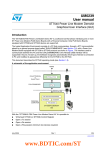
UM0863
User manual
M24LR64-R tool driver
install guide
1
Introduction
This user manual gives the procedures to install the different software drivers required to
use your development, demonstration and starter kits.
It also gives a description of the development, demonstration and starter kits, and explains
how to connect the RF and I²C readers to your computer.
December 2009
Doc ID 16789 Rev 1
1/40
www.st.com
Contents
UM0863
Contents
1
Introduction . . . . . . . . . . . . . . . . . . . . . . . . . . . . . . . . . . . . . . . . . . . . . . . . 1
2
Installing the setup.exe . . . . . . . . . . . . . . . . . . . . . . . . . . . . . . . . . . . . . . 5
3
Installing the drivers specific to the development kit
and demonstration kit . . . . . . . . . . . . . . . . . . . . . . . . . . . . . . . . . . . . . . . 10
3.1
Step1: Installing the drivers for the medium-range RF reader . . . . . . . . . 10
3.2
Step2: Installing the drivers for the I²C serial bus reader
(serial EEPROM USB reader) . . . . . . . . . . . . . . . . . . . . . . . . . . . . . . . . . 21
3.3
Trouble shooting . . . . . . . . . . . . . . . . . . . . . . . . . . . . . . . . . . . . . . . . . . . . 29
3.3.1
4
Tool kit descriptions . . . . . . . . . . . . . . . . . . . . . . . . . . . . . . . . . . . . . . . . 31
4.1
4.2
4.3
5
2/40
RF reader driver . . . . . . . . . . . . . . . . . . . . . . . . . . . . . . . . . . . . . . . . . . . 29
M24LR64-R’s development kit . . . . . . . . . . . . . . . . . . . . . . . . . . . . . . . . . 31
4.1.1
Ordering information . . . . . . . . . . . . . . . . . . . . . . . . . . . . . . . . . . . . . . . 31
4.1.2
Development kit package . . . . . . . . . . . . . . . . . . . . . . . . . . . . . . . . . . . . 31
M24LR64-R’s demonstration kit . . . . . . . . . . . . . . . . . . . . . . . . . . . . . . . . 33
4.2.1
Ordering information . . . . . . . . . . . . . . . . . . . . . . . . . . . . . . . . . . . . . . . 33
4.2.2
Demonstration kit package . . . . . . . . . . . . . . . . . . . . . . . . . . . . . . . . . . 33
M24LR64-R’s starter kit . . . . . . . . . . . . . . . . . . . . . . . . . . . . . . . . . . . . . . 35
4.3.1
Ordering information . . . . . . . . . . . . . . . . . . . . . . . . . . . . . . . . . . . . . . . 35
4.3.2
Starter kit package . . . . . . . . . . . . . . . . . . . . . . . . . . . . . . . . . . . . . . . . . 35
4.3.3
Connecting the readers and cables to your computer . . . . . . . . . . . . . . 37
4.3.4
Web support and references . . . . . . . . . . . . . . . . . . . . . . . . . . . . . . . . . 38
Revision history . . . . . . . . . . . . . . . . . . . . . . . . . . . . . . . . . . . . . . . . . . . 39
Doc ID 16789 Rev 1
UM0863
List of figures
List of figures
Figure 1.
Figure 2.
Figure 3.
Figure 4.
Figure 5.
Figure 6.
Figure 7.
Figure 8.
Figure 9.
Figure 10.
Figure 11.
Figure 12.
Figure 13.
Figure 14.
Figure 15.
Figure 16.
Figure 17.
Figure 18.
Figure 19.
Figure 20.
Figure 21.
Figure 22.
Figure 23.
Figure 24.
Figure 25.
Figure 26.
Figure 27.
Figure 28.
Figure 29.
Figure 30.
Figure 31.
Figure 32.
Figure 33.
Figure 34.
Figure 35.
Figure 36.
Figure 37.
Figure 38.
Figure 39.
Figure 40.
Figure 41.
Figure 42.
Figure 43.
Figure 44.
Figure 45.
Figure 46.
Figure 47.
Figure 48.
Setup - M24LRxx Application Software window . . . . . . . . . . . . . . . . . . . . . . . . . . . . . . . . . . 5
License Agreement window . . . . . . . . . . . . . . . . . . . . . . . . . . . . . . . . . . . . . . . . . . . . . . . . . 6
Installation path. . . . . . . . . . . . . . . . . . . . . . . . . . . . . . . . . . . . . . . . . . . . . . . . . . . . . . . . . . . 6
Creating the program shortcuts . . . . . . . . . . . . . . . . . . . . . . . . . . . . . . . . . . . . . . . . . . . . . . 7
Location of the application icon . . . . . . . . . . . . . . . . . . . . . . . . . . . . . . . . . . . . . . . . . . . . . . 7
Installing the user interface . . . . . . . . . . . . . . . . . . . . . . . . . . . . . . . . . . . . . . . . . . . . . . . . . . 8
Software README . . . . . . . . . . . . . . . . . . . . . . . . . . . . . . . . . . . . . . . . . . . . . . . . . . . . . . . . 8
Software installation completion . . . . . . . . . . . . . . . . . . . . . . . . . . . . . . . . . . . . . . . . . . . . . . 9
Messages that pop up when the RF reader is connected to the computer . . . . . . . . . . . . 10
Welcome to the Found New Hardware Wizard window . . . . . . . . . . . . . . . . . . . . . . . . . . . 11
“Install from a list or specific location (Advanced)” . . . . . . . . . . . . . . . . . . . . . . . . . . . . . . . 11
Search and installation options . . . . . . . . . . . . . . . . . . . . . . . . . . . . . . . . . . . . . . . . . . . . . . 12
Hardware type . . . . . . . . . . . . . . . . . . . . . . . . . . . . . . . . . . . . . . . . . . . . . . . . . . . . . . . . . . 12
Selecting the device driver . . . . . . . . . . . . . . . . . . . . . . . . . . . . . . . . . . . . . . . . . . . . . . . . . 13
Install from disk . . . . . . . . . . . . . . . . . . . . . . . . . . . . . . . . . . . . . . . . . . . . . . . . . . . . . . . . . . 13
Locate file . . . . . . . . . . . . . . . . . . . . . . . . . . . . . . . . . . . . . . . . . . . . . . . . . . . . . . . . . . . . . . 14
Select the obidusb.inf file and Open . . . . . . . . . . . . . . . . . . . . . . . . . . . . . . . . . . . . . . . . . . 14
Click “OK” to return to initial window . . . . . . . . . . . . . . . . . . . . . . . . . . . . . . . . . . . . . . . . . . 15
The driver has been selected . . . . . . . . . . . . . . . . . . . . . . . . . . . . . . . . . . . . . . . . . . . . . . . 15
Driver installation process. . . . . . . . . . . . . . . . . . . . . . . . . . . . . . . . . . . . . . . . . . . . . . . . . . 16
Installation complete . . . . . . . . . . . . . . . . . . . . . . . . . . . . . . . . . . . . . . . . . . . . . . . . . . . . . . 16
Start > Settings > Control Panel . . . . . . . . . . . . . . . . . . . . . . . . . . . . . . . . . . . . . . . . . . . . . 17
System Properties window . . . . . . . . . . . . . . . . . . . . . . . . . . . . . . . . . . . . . . . . . . . . . . . . . 18
Hardware tab . . . . . . . . . . . . . . . . . . . . . . . . . . . . . . . . . . . . . . . . . . . . . . . . . . . . . . . . . . . 19
Device Manager window. . . . . . . . . . . . . . . . . . . . . . . . . . . . . . . . . . . . . . . . . . . . . . . . . . . 20
Popup message . . . . . . . . . . . . . . . . . . . . . . . . . . . . . . . . . . . . . . . . . . . . . . . . . . . . . . . . . 21
Welcome to the Found New Hardware Wizard window . . . . . . . . . . . . . . . . . . . . . . . . . . . 21
“Install from a list or specific location (Advanced)” . . . . . . . . . . . . . . . . . . . . . . . . . . . . . . . 22
Search and installation options . . . . . . . . . . . . . . . . . . . . . . . . . . . . . . . . . . . . . . . . . . . . . . 22
Selecting the device driver to install . . . . . . . . . . . . . . . . . . . . . . . . . . . . . . . . . . . . . . . . . . 23
Browsing your computer . . . . . . . . . . . . . . . . . . . . . . . . . . . . . . . . . . . . . . . . . . . . . . . . . . . 23
File location. . . . . . . . . . . . . . . . . . . . . . . . . . . . . . . . . . . . . . . . . . . . . . . . . . . . . . . . . . . . . 24
Instal from disk . . . . . . . . . . . . . . . . . . . . . . . . . . . . . . . . . . . . . . . . . . . . . . . . . . . . . . . . . . 24
EEPROM USB drivers to be installed . . . . . . . . . . . . . . . . . . . . . . . . . . . . . . . . . . . . . . . . . 25
Software installation . . . . . . . . . . . . . . . . . . . . . . . . . . . . . . . . . . . . . . . . . . . . . . . . . . . . . . 26
Installation complete . . . . . . . . . . . . . . . . . . . . . . . . . . . . . . . . . . . . . . . . . . . . . . . . . . . . . . 27
Device Manager window. . . . . . . . . . . . . . . . . . . . . . . . . . . . . . . . . . . . . . . . . . . . . . . . . . . 28
Example where OBID is not correctly installed . . . . . . . . . . . . . . . . . . . . . . . . . . . . . . . . . . 29
Update Driver.... . . . . . . . . . . . . . . . . . . . . . . . . . . . . . . . . . . . . . . . . . . . . . . . . . . . . . . . . . 30
RF reader . . . . . . . . . . . . . . . . . . . . . . . . . . . . . . . . . . . . . . . . . . . . . . . . . . . . . . . . . . . . . . 31
External antenna. . . . . . . . . . . . . . . . . . . . . . . . . . . . . . . . . . . . . . . . . . . . . . . . . . . . . . . . . 31
I²C bus reader (serial EEPROM USB reader). . . . . . . . . . . . . . . . . . . . . . . . . . . . . . . . . . . 32
I²C bus cable. . . . . . . . . . . . . . . . . . . . . . . . . . . . . . . . . . . . . . . . . . . . . . . . . . . . . . . . . . . . 32
ANT1-M24LR-A reference antenna . . . . . . . . . . . . . . . . . . . . . . . . . . . . . . . . . . . . . . . . . . 32
ANT2-M24LR-A reference antenna . . . . . . . . . . . . . . . . . . . . . . . . . . . . . . . . . . . . . . . . . . 33
M24LR64-R in SO8 package . . . . . . . . . . . . . . . . . . . . . . . . . . . . . . . . . . . . . . . . . . . . . . . 33
RF reader . . . . . . . . . . . . . . . . . . . . . . . . . . . . . . . . . . . . . . . . . . . . . . . . . . . . . . . . . . . . . . 34
PRIM2-M24LR-A reference antenna . . . . . . . . . . . . . . . . . . . . . . . . . . . . . . . . . . . . . . . . . 34
Doc ID 16789 Rev 1
3/40
List of figures
Figure 49.
Figure 50.
Figure 51.
Figure 52.
Figure 53.
Figure 54.
Figure 55.
Figure 56.
Figure 57.
4/40
UM0863
STM32-PRIMER2 . . . . . . . . . . . . . . . . . . . . . . . . . . . . . . . . . . . . . . . . . . . . . . . . . . . . . . . . 34
Connecting your reference antenna to your STM32-PRIMER2 . . . . . . . . . . . . . . . . . . . . . 35
I²C & RF reader . . . . . . . . . . . . . . . . . . . . . . . . . . . . . . . . . . . . . . . . . . . . . . . . . . . . . . . . . 35
ANT1-M24LR-A reference antenna . . . . . . . . . . . . . . . . . . . . . . . . . . . . . . . . . . . . . . . . . . 36
ANT2-M24LR-A reference antenna . . . . . . . . . . . . . . . . . . . . . . . . . . . . . . . . . . . . . . . . . . 36
M24LR64-R in SO8 package . . . . . . . . . . . . . . . . . . . . . . . . . . . . . . . . . . . . . . . . . . . . . . . 36
External connector pinout of the serial I²C bus reader . . . . . . . . . . . . . . . . . . . . . . . . . . . . 37
External connector pinout of the M24LR64-R tag. . . . . . . . . . . . . . . . . . . . . . . . . . . . . . . . 37
Connecting the RF and I²C bus readers . . . . . . . . . . . . . . . . . . . . . . . . . . . . . . . . . . . . . . . 38
Doc ID 16789 Rev 1
UM0863
2
Installing the setup.exe
Installing the setup.exe
The setup.exe file is used to install all the drivers required by the
M24LRxx_Application_Software on your computer.
This setup.exe file has to be installed for the development, demonstration and starter kits.
Caution:
Please do NOT connect the USB cable(s) to your computer now.
●
Double click on the setup.exe file. The window shown in Figure 1 appears. Click on
“Next >” to continue.
Figure 1.
Setup - M24LRxx Application Software window
Doc ID 16789 Rev 1
5/40
Installing the setup.exe
●
Read the License Agreement and click on “I accept the agreement” if you agree (see
Figure 2).
Figure 2.
●
License Agreement window
Browse your computer to select the path where you want to install this software (see
Figure 3). Then click on Next.
Figure 3.
6/40
UM0863
Installation path
Doc ID 16789 Rev 1
UM0863
Installing the setup.exe
●
A new window opens to create the application shortcuts. By default, select “Next”,
otherwise, browse your computer (see Figure 4).
Figure 4.
●
Creating the program shortcuts
Define the type of icon you want then click “Next” (see Figure 5).
Figure 5.
Location of the application icon
Doc ID 16789 Rev 1
7/40
Installing the setup.exe
●
Install the user Interface software of the M24LR64-R tools (see Figure 6).
Figure 6.
●
Installing the user interface
The README information of the software is then displayed as shown in Figure 7.
Please read it carefully.
Figure 7.
8/40
UM0863
Software README
Doc ID 16789 Rev 1
UM0863
Installing the setup.exe
●
The first step of the installation process is over!
Figure 8.
Software installation completion
What is the status now?
●
The M24LRxx_Application_Sotware is now installed on your computer
●
You still have to install the drivers as described in Section 3: Installing the drivers
specific to the development kit and demonstration kit.
Doc ID 16789 Rev 1
9/40
Installing the drivers specific to the development kit and demonstration kit
3
UM0863
Installing the drivers specific to the development kit
and demonstration kit
This section describes how to install the drivers allowing your computer to interface the RF
reader and the I²C serial bus reader through the USB ports.
Note:
The starter kit does not need any specific installation driver.
3.1
Step1: Installing the drivers for the medium-range RF reader
You should first power up the RF reader and connect its USB cable to your computer. The
RF reader is then detected, and the popup messages shown in Figure 9 appear.
Figure 9.
10/40
Messages that pop up when the RF reader is connected to the computer
Doc ID 16789 Rev 1
UM0863
Installing the drivers specific to the development kit and demonstration kit
The “Found New Hardware Wizard” then starts up and you should follow the procedure
described below:
1.
The “Welcome to the Found New Hardware Wizard” window opens (see Figure 10).
Select “Yes, this time only”, and click on “Next >”.
Figure 10. Welcome to the Found New Hardware Wizard window
2.
In the next window (see Figure 11), select “Install from a list or specific location
(Advanced)”, and click on “Next >”.
Figure 11. “Install from a list or specific location (Advanced)”
Doc ID 16789 Rev 1
11/40
Installing the drivers specific to the development kit and demonstration kit
3.
As shown in Figure 12, select “Don’t search. I will choose the driver to install.”, and click
on “Next >”.
Figure 12. Search and installation options
4.
Then, like in Figure 13, select “Show All Devices”, and click on “Next >”.
Figure 13. Hardware type
12/40
UM0863
Doc ID 16789 Rev 1
UM0863
Installing the drivers specific to the development kit and demonstration kit
5.
In the next window (see Figure 14), click on “Have Disk…”.
Figure 14. Selecting the device driver
6.
Then, click on “Browse…” to locate the file (see Figure 15 and Figure 16).
Figure 15. Install from disk
Doc ID 16789 Rev 1
13/40
Installing the drivers specific to the development kit and demonstration kit
7.
Select the ObidUsb.inf file in the install directory. The default path is:
C:/Program File/M24LRxx_Application_Software/Driver/OBID USB driver/
Figure 16. Locate file
Click on “Open” (see Figure 17) and then on “OK” (see Figure 18)
Figure 17. Select the obidusb.inf file and Open
14/40
Doc ID 16789 Rev 1
UM0863
UM0863
Installing the drivers specific to the development kit and demonstration kit
Figure 18. Click “OK” to return to initial window
8.
The window now displays the OBID drivers that have been selected (see Figure 19).
Click on “Next >” to install the driver (see Figure 20).
Figure 19. The driver has been selected
Doc ID 16789 Rev 1
15/40
Installing the drivers specific to the development kit and demonstration kit
UM0863
Figure 20. Driver installation process
9.
When the installation is complete, click on “Finish” (see Figure 21).
Figure 21. Installation complete
The drivers allowing your computer to interface the RF reader are now installed. The
following step is described in Section 3.2: Step2: Installing the drivers for the I²C serial bus
reader (serial EEPROM USB reader).
16/40
Doc ID 16789 Rev 1
UM0863
Installing the drivers specific to the development kit and demonstration kit
Advanced information
You can verify that the medium-range RF reader drivers are correctly installed. OBID USB
Devices should be detected when the medium-range RF reader is plugged into your
computer’s USB port.
To check that the drivers are correctly installed, go to Start/Settings/Control Panel as shown
in Figure 22.
Figure 22. Start > Settings > Control Panel
Doc ID 16789 Rev 1
17/40
Installing the drivers specific to the development kit and demonstration kit
UM0863
In the Control Panel folder, double click on System. This causes the System Properties
window to open (see Figure 23).
Figure 23. System Properties window
18/40
Doc ID 16789 Rev 1
UM0863
Installing the drivers specific to the development kit and demonstration kit
Then click on the Hardware tab and then on Device Manager as shown in Figure 24.
Figure 24. Hardware tab
Doc ID 16789 Rev 1
19/40
Installing the drivers specific to the development kit and demonstration kit
UM0863
The Device Manager window opens (see Figure 25). “OBID USB Devices” should be
present.
Figure 25. Device Manager window
20/40
Doc ID 16789 Rev 1
UM0863
3.2
Installing the drivers specific to the development kit and demonstration kit
Step2: Installing the drivers for the I²C serial bus reader
(serial EEPROM USB reader)
Note that if you do not have to use the serial EEPROM USB reader, you do not need to
install these drivers.
To install the drivers: first, connect the USB cable between the I²C serial bus reader and
your computer. The I²C bus reader is then detected and the following popup message
appears (see Figure 26).
Figure 26. Popup message
The “Found New Hardware Wizard” then starts up and you should follow the procedure
described below:
10. The “Welcome to the Found New Hardware Wizard” window opens (see Figure 27).
Select “Yes, this time only”, and click on “Next >”.
Figure 27. Welcome to the Found New Hardware Wizard window
Doc ID 16789 Rev 1
21/40
Installing the drivers specific to the development kit and demonstration kit
UM0863
11. In the next window (see Figure 28), select “Install from a list or specific location
(Advanced)”, and click on “Next >”.
Figure 28. “Install from a list or specific location (Advanced)”
12. As shown in Figure 29, select “Don’t search. I will choose the driver to install.”, and click
on “Next >”.
Figure 29. Search and installation options
22/40
Doc ID 16789 Rev 1
UM0863
Installing the drivers specific to the development kit and demonstration kit
13. In the next window (see Figure 30), uncheck the box in front of “Show compatible
hardware” and click on “Have Disk…”.
Figure 30. Selecting the device driver to install
14. Then, click on “Browse…” to locate the file (see Figure 15 and Figure 16).
Figure 31. Browsing your computer
15. Browse your computer for the Serial_EEPROM_USB_Reader_driver.inf file. The
default path is:
Doc ID 16789 Rev 1
23/40
Installing the drivers specific to the development kit and demonstration kit
UM0863
C:/Program File/M24LRxx_Application_Software/driver/Serial EEPROM USB Reader
Driver/
Select the Serial_EEPROM_USB_Reader_driver.inf file and then click on “Open” (see
Figure 32) and “OK” (see Figure 33)
Figure 32. File location
Figure 33. Instal from disk
24/40
Doc ID 16789 Rev 1
UM0863
Installing the drivers specific to the development kit and demonstration kit
16. The window now displays the EEPROM USB drivers that have been selected (see
Figure 34). Click on “Next >” to install the driver (see Figure 35).
Figure 34. EEPROM USB drivers to be installed
Doc ID 16789 Rev 1
25/40
Installing the drivers specific to the development kit and demonstration kit
UM0863
17. During the installation, a new windows appears to inform you that the driver was not
certified by Microsoft®. Click on “Continue Anyway”. When the installation is complete,
click on “Finish” (see Figure 36).
Figure 35. Software installation
26/40
Doc ID 16789 Rev 1
UM0863
Installing the drivers specific to the development kit and demonstration kit
Figure 36. Installation complete
The drivers allowing your computer to interface the I²C bus reader are now installed.
Advanced information
You can check that the I²C bus reader drivers are installed by going to Start/Settings/Control
Panel/System. Click on the Hardware tab and then on Device Manager. In the Device
Manager the I²C bus reader should be shown as a USB peripheral (defined as Serial
EEPROM USB Reader, as shown in Figure 36).
Doc ID 16789 Rev 1
27/40
Installing the drivers specific to the development kit and demonstration kit
Figure 37. Device Manager window
28/40
Doc ID 16789 Rev 1
UM0863
UM0863
Installing the drivers specific to the development kit and demonstration kit
3.3
Trouble shooting
3.3.1
RF reader driver
You can check that the drivers for the RF and I²C bus readers are correctly installed by
viewing the “Device Manager” window.
In the example shown in Figure 38, you can see that the OBID is not correctly installed.
Figure 38. Example where OBID is not correctly installed
Right-click on “OBID RCI” and select “Update Driver...” as shown in Figure 39.
Doc ID 16789 Rev 1
29/40
Installing the drivers specific to the development kit and demonstration kit
UM0863
Figure 39. Update Driver...
You can now try to reinstall the reader drivers, as explained in Section 3.1: Step1: Installing
the drivers for the medium-range RF reader for the RF reader, and in Section 3.2: Step2:
Installing the drivers for the I²C serial bus reader (serial EEPROM USB reader) for the I²C
reader).
30/40
Doc ID 16789 Rev 1
UM0863
Tool kit descriptions
4
Tool kit descriptions
4.1
M24LR64-R’s development kit
4.1.1
Ordering information
The part number of the development kit is: DEVKIT-M24LR-A.
4.1.2
Development kit package
The development kit contains:
●
a middle-range RF reader (ISO 15693, RF 13.56 MHz) interfaced via the USB bus and
an external power supply to have a greater read range.
Figure 40. RF reader
●
an external antenna shown in Figure 41.
Figure 41. External antenna
ai17541
●
Serial EEPROM USB reader: I²C bus reader (interfaced via the USB bus). Figure 42
shows the reader.
Doc ID 16789 Rev 1
31/40
Tool kit descriptions
UM0863
Figure 42. I²C bus reader (serial EEPROM USB reader)
●
An I²C bus cable to connect the serial EEPROM USB reader and the I2C bus of the
reference antenna. Figure 43 shows the cable to use.
Figure 43. I²C bus cable
●
M24LR64-R’s reference antennas:
–
ANT1-M24LR-A: RF antenna size: 75 mm × 45 mm (2.9 in × 1.77 in) shown in
Figure 44.
–
ANT2-M24LR-A: RF antenna size: 20 mm × 40 mm (0.79 in x 1.57 in) shown in
Figure 45.
Figure 44. ANT1-M24LR-A reference antenna
32/40
Doc ID 16789 Rev 1
UM0863
Tool kit descriptions
Figure 45. ANT2-M24LR-A reference antenna
2&ANTENNA
-,22CHIP
)#CONNECTOR
6##6 333#,3$!
●
AI
M24LR64-R samples in SO8 package (see Figure 46).
Figure 46. M24LR64-R in SO8 package
4.2
M24LR64-R’s demonstration kit
4.2.1
Ordering information
The part number of the demonstration kit is: DEMOKIT-M24LR-A.
4.2.2
Demonstration kit package
The demonstration kit contains:
●
a middle-range RF reader (ISO 15693, RF 13.56 MHz) interfaced via the USB bus,
shown in Figure 47.
●
an M24LR64-R’s reference antenna: PRIM2-M24LR-A, RF antenna size: 20 mm ×
40 mm (0.79 in x 1.57 in) shown in Figure 48.
●
Optional: STM32-PRIMER2 (to be ordered separately) shown in Figure 49.
Doc ID 16789 Rev 1
33/40
Tool kit descriptions
UM0863
Figure 47. RF reader
Figure 48. PRIM2-M24LR-A reference antenna
2&ANTENNA
!.4-,2!DIMENSION
-,22CHIP
/PTIONAL
)#CONNECTOR
6##6 333#,3$!
%XTERNALCONNECTOR
FOR02)-%2
AI
Figure 49. STM32-PRIMER2
1. Not included in the kit, to be ordered separately.
34/40
Doc ID 16789 Rev 1
UM0863
Tool kit descriptions
Figure 50. Connecting your reference antenna to your STM32-PRIMER2
4.3
M24LR64-R’s starter kit
4.3.1
Ordering information
The part number of the starter kit is: STARTKIT-M24LR-A
4.3.2
Starter kit package
The starter kit contains:
●
a reader with an integrated solution for I²C communication (connector) and RF
communication (ISO 15693, RF 13.56 MHz) interfaced with a USB bus as shown in
Figure 51.
Figure 51. I²C & RF reader
Doc ID 16789 Rev 1
35/40
Tool kit descriptions
●
UM0863
M24LR64-R’s reference antennas:
–
ANT1-M24LR-A: RF antenna size: 75 mm × 45 mm (2.9 in × 1.77 in) shown in
Figure 44.
–
ANT2-M24LR-A: RF antenna size: 20 mm × 40 mm (0.79 in x 1.57 in) shown in
Figure 45.
Figure 52. ANT1-M24LR-A reference antenna
Figure 53. ANT2-M24LR-A reference antenna
2&ANTENNA
-,22CHIP
)#CONNECTOR
6##6 333#,3$!
●
AI
M24LR64-R samples in SO8 package (see Figure 46).
Figure 54. M24LR64-R in SO8 package
36/40
Doc ID 16789 Rev 1
UM0863
4.3.3
Tool kit descriptions
Connecting the readers and cables to your computer
Once the installation of the software drivers is complete (see previous sections Installing the
setup.exe and Installing the setup.exe), you have to physically connect the readers.
Connecting the RF reader
●
first, connect the external antenna to the RF reader
●
then, connect the power supply of the RF reader
●
you can now connect the RF reader to the USB port of your computer
The RF reader is ready to be used. Keep your tag on the external antenna to
communicate through the application software.
Connecting the I²C bus reader
●
First, connect the I²C bus reader to the USB port of your computer
●
then connect the I²C cable from the I²C bus reader to an M24LR64-R tag
Figure 55. External connector pinout of the serial I²C bus reader
)#BUSREADER
)#3#,
)#3$!
)#6 33
)#6 ##
%XTERNALCONNECTORPINOUT
AI
Figure 56. External connector pinout of the M24LR64-R tag
Doc ID 16789 Rev 1
37/40
Tool kit descriptions
UM0863
Figure 57. Connecting the RF and I²C bus readers
4.3.4
Web support and references
ST products (M24LR64-R datasheet, application notes, etc.)
Serial EEPROM USB reader
Software
For further information and copies of the available technical documentation, please
contact your nearest ST sales office.
FEIG ELECTRONICS RF readers
http://www.obid.eu/
http://www.feig.de/
eStar RF & I²C reader
http://www.estarcorp.net/en/index.asp
STM32-PRIMER2
http://www.raisonance.com/
http://www.stm32circle.com/
You can now enjoy your kit!
38/40
Doc ID 16789 Rev 1
UM0863
5
Revision history
Revision history
Table 1.
Document revision history
Date
Revision
30-Nov-2009
1
Changes
Initial release.
Doc ID 16789 Rev 1
39/40
UM0863
Please Read Carefully:
Information in this document is provided solely in connection with ST products. STMicroelectronics NV and its subsidiaries (“ST”) reserve the
right to make changes, corrections, modifications or improvements, to this document, and the products and services described herein at any
time, without notice.
All ST products are sold pursuant to ST’s terms and conditions of sale.
Purchasers are solely responsible for the choice, selection and use of the ST products and services described herein, and ST assumes no
liability whatsoever relating to the choice, selection or use of the ST products and services described herein.
No license, express or implied, by estoppel or otherwise, to any intellectual property rights is granted under this document. If any part of this
document refers to any third party products or services it shall not be deemed a license grant by ST for the use of such third party products
or services, or any intellectual property contained therein or considered as a warranty covering the use in any manner whatsoever of such
third party products or services or any intellectual property contained therein.
UNLESS OTHERWISE SET FORTH IN ST’S TERMS AND CONDITIONS OF SALE ST DISCLAIMS ANY EXPRESS OR IMPLIED
WARRANTY WITH RESPECT TO THE USE AND/OR SALE OF ST PRODUCTS INCLUDING WITHOUT LIMITATION IMPLIED
WARRANTIES OF MERCHANTABILITY, FITNESS FOR A PARTICULAR PURPOSE (AND THEIR EQUIVALENTS UNDER THE LAWS
OF ANY JURISDICTION), OR INFRINGEMENT OF ANY PATENT, COPYRIGHT OR OTHER INTELLECTUAL PROPERTY RIGHT.
UNLESS EXPRESSLY APPROVED IN WRITING BY AN AUTHORIZED ST REPRESENTATIVE, ST PRODUCTS ARE NOT
RECOMMENDED, AUTHORIZED OR WARRANTED FOR USE IN MILITARY, AIR CRAFT, SPACE, LIFE SAVING, OR LIFE SUSTAINING
APPLICATIONS, NOR IN PRODUCTS OR SYSTEMS WHERE FAILURE OR MALFUNCTION MAY RESULT IN PERSONAL INJURY,
DEATH, OR SEVERE PROPERTY OR ENVIRONMENTAL DAMAGE. ST PRODUCTS WHICH ARE NOT SPECIFIED AS "AUTOMOTIVE
GRADE" MAY ONLY BE USED IN AUTOMOTIVE APPLICATIONS AT USER’S OWN RISK.
Resale of ST products with provisions different from the statements and/or technical features set forth in this document shall immediately void
any warranty granted by ST for the ST product or service described herein and shall not create or extend in any manner whatsoever, any
liability of ST.
ST and the ST logo are trademarks or registered trademarks of ST in various countries.
Information in this document supersedes and replaces all information previously supplied.
The ST logo is a registered trademark of STMicroelectronics. All other names are the property of their respective owners.
© 2009 STMicroelectronics - All rights reserved
STMicroelectronics group of companies
Australia - Belgium - Brazil - Canada - China - Czech Republic - Finland - France - Germany - Hong Kong - India - Israel - Italy - Japan Malaysia - Malta - Morocco - Philippines - Singapore - Spain - Sweden - Switzerland - United Kingdom - United States of America
www.st.com
40/40
Doc ID 16789 Rev 1