1
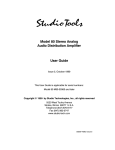
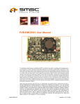
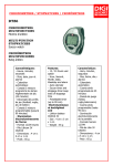
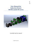
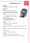
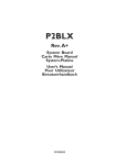
DS248A
Multi Effects Processor
USER MANUAL
CONTENTS
Safety Instruction
1
Characteristic
2
Control Panel
3
Operation Content
4
Specification
10
CAUTION
RISK OF ELECTRIC SHOCK
DO NOT OPEN
CAUTION: TO REDUCE THE RISK OF ELECTRIC
SHOCK DO NOT REMOVE COVER ( OR BACK)
NO USER-SERVICEABLE PARTS INSIDE
REFER SERVICING TO QUALIFIED PERSONNEL
The lightning flash with arrowhead synbol within an equilateral
triangle is intended to alert the user to the presence of
uninsulated dangerous voltage within the product's enclosure,
that may be of sufficient magnitude to constitute a risk of electric
shock to persons.
The exclamation point within an equilateral triangle is intended
to alert the user to the presence of important operation and
maintenace (servicing) instruction in the literature
accompanying the appliance.
IMPORTANT SAFETY INSTRUCTION
Please read below basic protection proceeding before using
1. Please read all the safety instruction before using the product.
2. This product must be earthed. If it should be malfunction or break down, grounding provides a path of least resistance
for electric current to reduce risk of electric shock.
This product is equipped with a cord having an equipment-grounding conductor and a grounding plug. The plug must be
plugged into an appropriate outlet that is properly installed and earthed in accordance with all local codes and ordinance.
DANGER- Improper connection of the equipment-grounding conductor can result in a risk of electric shock. Check with
a qualified electrician or serviceman if you are in doubt as to whether the product is properly grounded. Do not modify the
plug provided with the product - if it will not fit the outlet, have a proper outlet installed by a qualified electrician.
3. To reduce the risk of injury, close supervision is necessary when the product is used near children.
4. Do not use this product near water-for example, near a bathtub, washbowl, kitchen sink, in wet basement or near a
swimming pool or the lake.
5. This product may be capable of producing sound levels that cloud cause permanent hearing loss. Do not operate for a
long period of time at high volume level or at a level that is uncomfortable. If you experience any hearing loss or ringing
in the ears, you should consult an audiologist.
6. This product should be located so that its location or position does not interfere with its proper ventilation.
7. This product should be located away from heat sources such as radiators, heat registers or other products that produce heat.
8. The product should be connected to a power supply only of the type described on the operation instructions or as marked
on the product.
9. This product may be equipped with a polarized line plug (one blade wider than the other). This is a safety feature. If you
are unable to insert the plug into the outlet, contact an electrician to replace your obsolete outlet. Do not defeat the safety
purpose of the plug.
10.The power-supply cord of the product should be unplugged from the outlet when left unused for a long period of time.
When unplugging the power-supply cord, do not pull on the cord, but grasp it by the plug.
11.Care should be taken so that object do not fall and liquid are not spilled into the enclosure through opening.
12.The product should be serviced by qualified service personnel when:
A. The power-supply cord or the plug has been damaged; or
B. Objects have been fallen, or liquid has been spilled into the product; or
C. The product has been exposed to rain; or
D. The product does not appear to operate normally or exhibits a marked change in performance; or
E. The product has been dropped or the enclosure damaged..
13.Do not attempt to service the product beyond that described in the user-maintenance instructions. All other servicing
should be referred to qualified service personnel.
14 WARNING- Do not place objects on the product's power cord or place it in a position where anyone could trip over,
walk on or roll anything over it. Do not allow the product to rest on or to be installed over power cords of any type. Improper
installations of this type create the possibility of fire hazard and/or personal injury.
SAVE THESE INSTRUCTIONS
Page 1
Characteristic
DIGISYNTHETIC
PRO MODE DS248A
24-bit high pevformance DSP, 48 kHz sampling rate.
48 Factory preset effects, 48 user editable effective programme.
Including mix,chorus,pit,dist effects,suitable for different users.
5 band parametric equalizer.
2x16 charactor LCD display.
LEV level lamp bar display..
Simple GUI control and reserved function.
Page 2
Control panel
Front panel
1
2
3
4
5
6
7
8
9
10
6
3
7
9
10
PROGRAM Button,use to shift preset programme mode/user mode.
LOCK button:use to lock the button,prevent mistaken operation.
BYPASS Button use to through on/off effect.
Signal Meter: indicates the level of the signal input .
2X16 LCD dislay.
Encoder: Use to adjust the parameter.
PARAMETER Button Shift effect parameters menu.
EQ/RESET Button: To shift EQ menu and reset operation.
Store Button: Use to stare operation.
Power switch.
Rear panel
1
1
2
3
4
5
6
7
8
2
8
5
4
1
4
2
3
7
5
6
8
Power socket.
USB connector.
Right Channel output.
Right Channel input level adjustment.
Right Channel input.
Left Channel output.
Left Channel input level adjustment.
Left Channel inputs.
Page 3
Operation content
A
Introduction
DS248A is a multi-effects processor designed with flexibility & user friendly for all venues & events.
Available 48 factory preset effects for instant operation (P1 ~P48). Also available 48 effects for user program
(U1~U48).All parameters are editable with memory function, included:
(1)
Reverb parameter:
"REV MIX"- Reverb effect-mixing volume.
"PreDelay" - Rever bpre delay time.
"REV TIME"- Reverb Time.
"REV LPF"- Reverb Lowpass filter.
"REV HPF"- Reverb Highpass filter.
"REV HDAMP"- HF reverb HDAMP enchance.
(2)
Gate reverb editalbe parameter:
"GT MIX"- Gate reverb mixing volume.
"PreDelay"- Predelay time.
"GT TIME"- Gate reverb time.
"GT LPF - Lowpass filter.
"GT HPF"- High pass filter.
"GT HDAMP"- HF enchance.
"GT THRES"- threshold value.
(3)
ECHO Parameters
Echo Mix: Echo Volumne.
E.TIME: Echo Time.
E.HPF: Echo High Pass Rilter.
E.LPF: Echo Low Pass Rilter.
E.FB: Echo FeedBack.
E.HDAMP: HF Enchance.
(4)
Chorus parameters:
"CHO MIX"- CHORUS Volume.
"CHO DELAY"- Chorus delay time.
"CHO FB"- Chorus feedback.
"CHO HPF"- Chorus Highpass filter.
"CHO RATE"- Chorus rate.
"CHO DEPTH"- Chorus depth.
Page 4
Operation content
(5) Flanger Parameters:
"FLG MIX"-Flange mixing volume.
"FLG DELAY"- Flange delay time.
"FLG FB"- Flange feedback.
"FLG HPF"- Flange Highpass filter.
"FLG RATE"- Flange rate.
"FLG DEPTH"- Flange depth.
(6) Delay parameter:
"DEL MIX"- Delay mixing volume.
"DEL TIME"- Delay Time.
"DEL FB"- Delay Feedback.
"DEL HPF"- Delay highpass filter.
(7) Pitch parameters:
"PIT MIX"- Pitch mixing volume.
"PIT COARSE"- detune.
"PIT FREQ"- Pitch frequency.
"PIT RES"- Pitch resonance.
(8) Distortion parameters:
"DIST DEPTH"- distortion depth.
"DIST LPF"- Distortion Low Pass Filter.
"DIST RES"-Distortion Resonance.
"DIST FILT"- Distortion filt.
Page 5
Operation content
B
EFFECTS MENU Display
PO1:CATHEDRAL
1
1
REV MIX:70%
2
Fig.2.1: EFFECTS Menu Display
(1) 1st line to display effect modes.
(2) 2nd line to display parameters.
(3) " : " flashing is that current programme can edit.
C
Function Buttons & Program Jog Wheel
6
2
4
PROG
LOCK
BYPASS
EQ
STORE
PARAM
8
RESET
3
5
I
0
7
Fig.2.2: Function dencoder Buttons
(1) To edit parameter value, turning clockwise to increase and anti-clockwise to decrease value, "SV"
flashing is prompting that the parameter has been changed,whether memories.
(2) PROG- Press this button to select program and LCD screen will display program effect (as Fig. 2.3),
and this " : " symbol flashing to user can choose any effecs from P1-P48 preset effect through encoder,
and press the button again,show user purposed effects.
PO1:CATHEDRAL1
REV MIX:70%
Fig.2.3: Factory preset Default program
Page 6
Operation content
(3) PARAM-PARAMETER BUTTON
Press this button to display second line information of present program parameter. " : " flash to allow
parameter adjustment by jog wheel. Repeat pressing this button to select different parameter items and
turning jog wheel to increase or decrease value. While "SV" flash and display on top right or bottom right
screen means parameter has been edited and remind user to save changes or not. Press button 7 (STORE)
to store edited value. Example: To edit "P 02" entire parameter value. Press this button shortly to
show "REV MIX: 50%" on second line of LCD Screen. " : " symbol will blink, turning jog wheel clockwise
to increase "MIX : 50%" to "MIX : 70%", hold "PARAM" button shortly again to display second line
information with "REV TIME: 2.0s". " : " symbol blink, turn jog wheel anti-clockwise to decrease "2.0s"
to "1.9s". Press " PARAM" button, "REV HPF" will display in second line, " : " symbol blinks, turning
jog wheel clockwise or anti-clockwise to increase or decrease parameter value respectively.
UO2:CATHEDRAL2
REV MIX:70%
Fig.2.4: USER PROGRAM
(4) LOCK- First hold this button for longer seconds to display first line information with the last " " symbol,
this shows Function Button is in LOCK mode situation ( as Fig 2.5). Other than this button, the rest of the
button is not functioning. 2nd time holding this button for longer seconds to disable the 1st line last " " symbol,
this means the LOCK mode function is disable, all buttons resume to its original function.
PO1:CATHEDRAL
REV MIX:70%
Fig.2.5: Function Button LOCK mode
(5) PEQ/RESET- Parametric EQ & Reset Button. Press this button shortly to activate Parametric EQ Octave,
nd
2 line will display frequency gain. " : " indicate it can edit curvent programme ( as Fig 2.6). First press
this button, " : " will blink in 1st line display, turning jog wheel to select any item from 62Hz,250Hz,1kHz,
2kHz,8kHz. Press this button again,From the las will blink, at this time the user is able to select
GAIN from "-12dB~+12dB". Press this button again to go back to the 1st line function. Hold this button
for more than 3 seconds to RESET function. Present program will be reset to factory default settings
(as Fig 2.4).
EQ FREQ:1kHz
GAIN:0dB
Fig.2.6: Equalizer programs
(6) BYPASS- If hold this button for longer seconds, signal will send out directly with out
any sound effect (as Fig 2.7). Hold this button again for longer period to resume to program function.
BYPASS
OK
Fig.2.7: Effect off indication
Page 7
Operation content
(7) STORE- Press this button to SAVE edited parameter values. Able to STORE to any User program from
U1- U48. If "U01" blink, SV blinks, this indicates user is able to select any user program from U01 ~U48
by jog wheel (as Fig. 2.8). Press this button again, "STORE" will blink (as Fig. 2.4), go back to USER
PROGRAM mode and the previous changes has been SAVED.
U01:CATHEDRAL1
REV MIX:70% SV
Fig 2.8: SAVE MODE
Keep pressing STORE key 3 seconds, LCD screen will dislay "BATCH SETTING DIRECT VOL: 0%, then
able to set U1-U48 direct sound revolve knob to set the volume. To hold longer press this button till the LCD
screen dispaly "ETTING BATCH DIRECT VOL, PLS WAIT", then you can make the same volume seting
for U1-U48
D
48 Appendix Effect Lists
1
2
3
4
5
6
7
8
9
10
11
12
13
14
15
16
17
18
19
20
21
22
23
24
25
26
27
28
Page 8
CATHEDRAL
SHORT ROOM1
SHORT ROOM2
SHORT ROOM3
ROOM 1
ROOM 2
SMALL HALL1
SMALL HALL2
LARGE HALL1
LARGE HALL2
SHORT PLATE
VOCAL PLATE
CHURCH 1
CHURCH 2
DELAY 1
DELAY 2
TRIPLET DLY
MUL TAP DLY
GATED REVB1
GATED REVB2
GATED PLAT1
GATED PLAT2
STEREO ECHO
TRIPL ECHO
CHO LIGHT 1
CHO LIGHT 2
CHO MEDIUM1
CHO MEDIUM2
Operation content
29
30
31
32
33
34
35
36
37
38
39
40
41
42
43
44
45
46
47
48
CHO DEEP 1
CHO DEEP 2
CHO FAST 1
CHO FAST 2
RESONAN CHO
LONG-TM CHO
LESLIE SLOW
PITCH
DEL & REV 1
DEL & REV 2
CHO & REV 1
CHO & REV 2
FLA & REV 1
FLA & REV 2
CHO & DEL 1
CHO & DEL 2
DIST & CHO
DIST & DEL
DIST & GATE
PITCH&DELAY
Page 9
Specification
E
Technical Specifications
Analog Inputs
Connectors
Type
Impedance
Input Operating Level
Max. Input Level
XLR and 1/4" jack
therefore filtered, servo balanced , 20k
40k balanced, 20k unbalanced
-20dB to +4dB
+4Vpp
Analog Outputs
Connectors
Type
Impedance
Max. Output Level
XLR and 1/4 Inch jack
Electronically servo-balanced output stage
<100
+-2dBu, 600
System specifications
Bandwidth
20Hz to 20KHz -0.25dB
THD
Channel Separation
0.035%typ. 1KHz, 0 dBu INPUT
>60dB, 1KHz, o dBu input
Digital Processing
Converters
Sampling Rate
24-bit Sigma-Delta, 64/128-times Over-sampling
48KHz
Display
Type
2x16 LCD-Display
Power Supply
~ 90V-250VAC
Fuse
T1AL/250VAC
Power Consumption
Mains Conection
10 Watts
Standard IEC receptacle
Physical
Dimensions(H*W*D)
Net weight
Gross Weight
45mm 482mm 152mm
2kg
3kg
Page 10
unalanced