1
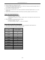
© Performance Electronics, Ltd. Active Voltage Low: Less than 2.0 volts Frequency Input Range (Digital Inputs 1-4): 0-6000 Hz, Frequency must be greater than 0.5 Hz to register something other than 0 Hz. Max Continuous Voltage Input: 22v Digital inputs activated with 5-22 volts are pulled low internally (Digital inputs #1, #2, #3, #4 and #5) Digital inputs activated with GND are pulled high internally (Digital inputs #6 and #7) Trigger/Sync Input Specifications When Configured as Hall Effect Sensor o Max Input Voltage: Up to Vbat o Input Voltage Threshold to Trigger: Greater than 4.0 volts high side, less than 400 mv low side When Configured as Variable Reluctance Sensor o Max Input Voltage: 100 volts o Min Input Voltage to trigger: +/- 250 mv (0 to peak) Sensor and User Data Filter Characteristics Filter Type: Single-Pole, low-pass digital filter with configurable break frequencies Filter Break Frequencies based on the table below Filter Setting Break Freq (Hz) Off No filter applied Level 1 73 Level 2 62 Level 3 51 Level 4 40 Level 5 30 Level 6 20 Level 7 16 Level 8 10 Level 9 5 Level 10 4 Level 11 3 Level 12 2 Level 13 1 Level 14 .5 Level 15 .2 -143-