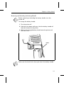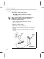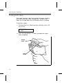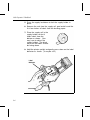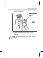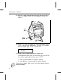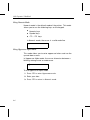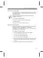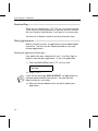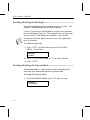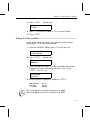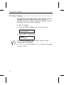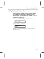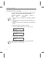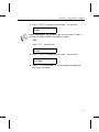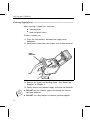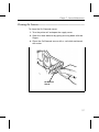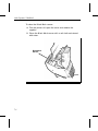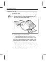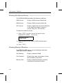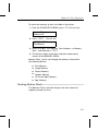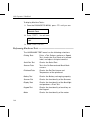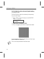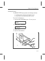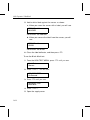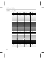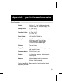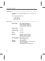
1
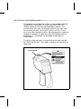
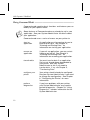
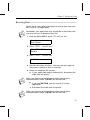
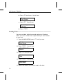
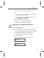
M Monarch ® 6030 PATHFINDER ® Ultra Printer TM TM Operator’s Handbook TC6030OH Rev. E 10/97 ©1994 Monarch Marking Systems, Inc. All rights reserved. Each product and program carries a respective written warranty, the only warranty on which the customer can rely. Monarch reserves the right to make changes in the product, the programs, and their availability at any time and without notice. Although Monarch has made every effort to provide complete and accurate information in this manual, Monarch shall not be liable for any omissions or inaccuracies. Any update will be incorporated in a later edition of this manual. WARNING This equipment has been tested and found to comply with the limits for a Class A digital device, pursuant to Part 15 of the FCC Rules. These limits are designed to provide reasonable protection against harmful interference when the equipment is operated in a commercial environment. This equipment generates, uses, and can radiate radio frequency energy and, if not installed and used in accordance with the instruction manual, may cause harmful interference to radio communications. Operation of this equipment in a residential area is likely to cause harmful interference in which case the user will be required to correct the interference at his own expense. CANADIAN D.O.C. WARNING This digital apparatus does not exceed the Class A limits for radio noise emissions from digital apparatus set out in the Radio Interference Regulations of the Canadian Department of Communications. Le présent appareil numérique n’émet pas de bruits radioélectriques dépassant les limites applicables aux appareils numériques de la classe A prescrites dans le Réglement sur le brouillage radioélectrique édicte par le ministère des Communications du Canada. Monarch®, PATHFINDER®, PATHFINDER® Ultra , 6030 , 6076 , 6093 , and 6094 are trademarks of Monarch Marking Systems, Inc. Laser Scanner Safety Information ––––––––––––––––––––––––––––– This product is certified to be a Class II laser product with the United States Department of Health and Human Services (DHHS) Center for Devices and Radiological Health. The scanner emits less than 1.0 milliwatt beam of laser light from the scanning window. Laser light in excess of Class I limits must be inside a protective cover. No maintenance is required to keep this product in compliance with DHHS Regulation 21, Subchapter J. No controls are provided for operation or maintenance. The laser safety warning is a yellow and black label required by DHHS and IEC 825. This label is found on the top cover of the printer. Laser Window Preface The Operator’s Handbook contains product specifications and accessories, including information about F charging the battery handle. F loading supplies. F using the keypad. F starting an application and transferring data. F collecting data and printing. F using the optional laser scanner. F caring for and maintaining the printer. F troubleshooting. Audience ––––––––––––––––––––––––––––––––––––––––––––––––––– The Operator’s Handbook is for both the Operator and System Administrator. The Operator is the person who collects data and/or prints and applies labels or tags. The System Administrator may use Command mode to set up specific features and functions of the printer for the operator. Terms to Know–––––––––––––––––––––––––––––––––––––––––––––– Application Program in the printer that may prompt you for data, scan bar codes, print labels, etc. This program is developed by a programmer with your specific needs in mind, and then is downloaded to your printer. i 6030 Operator’s Handbook Command mode Series of menus on your printer display from which you can start/resume applications, transfer data, configure the printer or use diagnostics. Continuous mode Print mode in which a strip of supplies is printed with one press of the trigger. Download (receive) Transmission of data from the host to your printer. ii Host Any mainframe, minicomputer, or personal computer (PC). Lowercase Alpha mode Data Entry mode that allows you to use lowercase letters. Also enters and exits the alternate character set for International models. Non-Peel mode Supply loading method in which labels are not peeled from the backing paper during printing. Numeric mode Data Entry mode that allows you to use function and number keys. On-Demand mode Print mode in which one label prints each time you remove the previously printed label. Peel mode Supply loading method in which the label peels from the backing paper during printing. Special Character mode Data Entry mode that allows you to enter ANSI characters. Uppercase Alpha mode Data Entry mode that allows you to use uppercase letters. Upload (send) Transmission of data from your printer to the host. Chapter 1. Introduction This printer can be programmed to fit your specific needs. You can use it to scan data or print labels specially designed for you. In order to use the printer, an application that includes your format and printer configuration must be downloaded. See your System Administrator for details. The printer features F Alphanumeric keypad F On-Demand and continuous printing F Adjustable supply width capabilities F Clock/calendar F RS-232 communications F Graphic printing capabilities F Display backlight F Low power shutdown to conserve the battery F Command mode F Laser scanner (factory-installed option) F Additional RAM memory (factory-installed option) F International keypad (factory-installed option). See Appendix B, "Specifications and Accessories," for a list of available accessories. 1-1 6030 Operator’s Handbook Using Command Mode –––––––––––––––––––––––––––––––––––––– Command mode contains basic functions and features you can modify for your specific needs. n Some features of Command mode may already be set in your application. See your System Administrator for details about your application. Command mode uses a series of menus on your printer to 1-2 start an application An application must be running for you to enter or print data. See Chapter 4, "Entering and Printing Data," for information on starting your application. resume an application If you exit an application, you may restart it where you left off. See Chapter 4, "Entering and Printing Data," for information on resuming your application. transfer data You must transfer data if an application file has not already been downloaded to your printer. See your System Administrator to see if you need to transfer data. If so, see Chapter 5, "Transferring Data." configure your printer Your printer should already be configured. See your System Administrator if you need to change the configuration. See Chapter 6, "Configuring the Printer," for more information. perform diagnostics If you have problems with your printer, your System Administrator may need to perform diagnostics. Chapter 10, "Using Diagnostics," includes information for the System Administrator. Chapter 1. Introduction Using the Menus –––––––––––––––––––––––––––––––––––––––––––– The Command mode uses a series of menus you can scroll through to access the functions you need. The menu names appear in uppercase letters on line 1. The menu selection(s) appear with only the first letter capitalized on line 2 of the display as shown. MAIN MENU Resume App. While in Command mode, use the following keys: e Executes the selection displayed on line 2. b Returns to the current menu or MAIN MENU. < > Scrolls through the menu selections. To select an item from the MAIN MENU: 1. Press the arrow keys until you see the item you want. 2. Press e. Repeat these steps to select an item from any sub-menu. 1-3 6030 Operator’s Handbook 1-4 Chapter 2. Getting Started Before using the printer, you must 4 charge the battery handle. (See "Charging the Battery Handle" later in this chapter.) 4 attach a fully charged battery handle. (See "Removing and Attaching the Battery Handle" later in this chapter.) 4 load your supplies. (See Chapter 3, "Loading Supplies.") 4 download your application, if necessary. (See Chapter 5, "Transferring Data.") n See your System Administrator for information about the application. Using the Battery Handle –––––––––––––––––––––––––––––––––––– The printer is powered by a 12VDC NiCd battery in the handle. You can use and recharge the battery handle daily for approximately two years. n See the label on the bottom of the handle about battery recycling and disposal. When the battery handle is not in use and not recharging, it loses 2 to 3% of its charge per day. Extremely hot or cold environments will increase or decrease the discharge rate. Keep the battery handle charging when it is not in use. This way, the printer is ready when you need it. 2-1 6030 Operator’s Handbook The following will increase the battery discharge rate c F using the laser scanner F enabling the backlight F printing large amounts of data on the supply F printing in On-Demand mode. Always keep a charged handle attached to the printer. Storing the printer without a handle may erase or alter the memory. Charge the handles for the time recommended. When to Charge the Battery Handle Before operating the printer, charge the battery handle and attach it to the printer. You can use one of the following chargers. Charger Approximate Charging Time 6093-07 115V (fast) 6093-08 230V (fast) 6094 Four Station 1.5-2 hours 1.5-2 hours 1.5 hours To ensure maximum print quality, charge the battery handle: 2-2 F before lengthy printing sessions. F when loading a new supply roll. F before transmitting data online. F when you see RECHARGE on the printer display. Chapter 2. Getting Started Removing and Attaching the Battery Handle c Before removing or attaching the battery handle, turn the printer off. To change the battery handle: 1. Turn the printer off. 2. Hold the latch down while you slide the battery handle off towards the back of the printer. 3. Slide a fully charged battery handle onto the printer until the latch clicks. Latch n Make sure the latch clicks when you attach the battery handle. 2-3 6030 Operator’s Handbook Charging the Battery Handle When using or storing the wall charger: F DO NOT wrap the cord around the charger. F DO NOT pull or put unusual stress on the cord. w Before using the charger, inspect the cord for bare wires. DO NOT use a charger with bare wires. Use only a manufacturer approved charger. To charge the battery handle with the wall charger: 1. Turn the printer off. 2. Remove the battery handle. 3. Put another handle on the printer. 4. Plug the round connector of the charger into the battery handle. 5. Plug the charger into an electrical outlet of the correct voltage. Charger Battery Handle Connector 2-4 Chapter 3. Loading Supplies The printer uses thermal supplies: F synthetic labels F paper labels and tags F specialty paper (non-peel mode only) See Appendix B, "Specifications and Accessories," for available supply sizes. Loading Supplies–––––––––––––––––––––––––––––––––––––––––––– There are two methods for loading supplies: F Peel mode is for labels only. Labels must be loaded in Peel mode when the On-Demand sensor is enabled. F Non-Peel mode is for tags, strips of labels, or specialty paper. Supply must be loaded in Non-Peel mode when printing in continuous mode. 3-1 6030 Operator’s Handbook Loading for Peel Mode––––––––––––––––––––––––––––––––––––––– Peel mode separates labels from the backing paper, allowing you to print and apply labels immediately. You must load labels in this mode when the On-Demand sensor is enabled. To load your supply: 1. Turn the printer on. After the printer initializes, press l. You will see: RELOADING_ 1 = Exit 2. Press the latch buttons as shown and open the supply cover completely. Supply Cover Latch Button 3-2 Chapter 3. Loading Supplies 3. Pull back the supply lock tab. 4. Squeeze or pull apart the supply holder at its base to adjust it to the size of your supply roll. It clicks at 1.2", 1.5", and 2.0". Supply Holder 3-3 6030 Operator’s Handbook 5. Press the supply lock down to lock the supply holder in place. 6. Remove the seal from the supply roll, peel and discard the first four inches of labels from the backing paper. 7. Place the supply roll in the supply holder so that it feeds labels from the bottom as shown. (You may have to adjust the supply holder.) The black marks on the labels should be facing down. 8. Hold the printer upright and gently press down on the label deflector as shown. (It may be stiff.) Label Deflector 3-4 Chapter 3. Loading Supplies 9. Feed the backing paper under the applicator roller and under the label deflector. Applicator Roller Label Deflector 10. Push the label deflector up until it snaps into place. 11. Partially close the supply cover to the first position (until it clicks once). n Do Not close the cover completely at this step or a label jam may occur. 3-5 6030 Operator’s Handbook 12. Hold the supply edge between the feed and pinch rollers. Press the trigger to feed the backing paper through the rollers. Feed Roller Pinch Roller 13. Press 1 if you are loading the same supply type. Press e to start your application. Or, press 2 to load a different supply type or size. You will see: Supply Type? 1 = Synthetic 14. Press e if this is the correct supply type. To change the supply type, use the arrow keys to scroll to the correct supply type and then press e. 1 = High (recommended for synthetic supplies) 2 = Low (default - recommended for paper supplies) n 3-6 Do not select Supply Types 3 or 4 since they require different loading methods. Chapter 3. Loading Supplies You will see: Supply Width? WIDTH = 2.0 15. Press e if this is the correct width. -ORTo change the width, use the arrow keys to scroll to the correct width and then press e. 1 = 1.2 2 = 1.5 3 = 2.0 You will see: ENTER STK LENGTH 4.0z 16. Press e if this is the correct length. -ORTo change the length, press c, enter the new length, and press e. 17. Close the supply cover completely. 3-7 6030 Operator’s Handbook Loading for Non-Peel Mode –––––––––––––––––––––––––––––––––– Non-Peel mode feeds the supply through the printer in one continuous strip. Use Non-Peel mode to print strips of labels, tags, or specialty paper. To load your supply: 1. Turn the printer on. After the printer initializes, press l. You will see: RELOADING_ 1 = Exit 2. Press the latch buttons as shown and open the supply cover completely. Supply Cover Latch Button 3-8 Chapter 3. Loading Supplies 3. Pull back the supply lock tab. 4. Squeeze or pull apart the supply holder at its base to adjust it to the size of your supply roll. It clicks at 1.2", 1.5", and 2.0". Supply Holder 3-9 6030 Operator’s Handbook 5. Press the supply lock down to lock the supply holder in place. 6. Remove the seal from the supply roll. 7. Place the supply roll in the supply holder so that it feeds labels from the bottom as shown. (You may have to adjust the supply holder.) The black marks on the labels should be facing down. n There are no black marks on specialty paper. 8. Feed the backing paper under the applicator roller and over the label deflector. Applicator Roller Label Deflector 3-10 Chapter 3. Loading Supplies 9. Close the supply cover completely. 10. Press 1if you are loading the same supply type. Press eto start your application. Or, press 2 to load a different supply type or size. You will see: Supply Type? 1 = Synthetic 11. Press e if this is the correct supply type. To change the supply type, use the arrow keys to scroll to the correct supply type and then press e. 1 = High (recommended for synthetic supplies) 2 = Low (default- recommended for paper supplies) 3 = Specialty Paper n Do not select Supply Type 4 since it requires a different loading method. You will see: Supply Width? WIDTH = 2.0 12. Press e if this is the correct width. -ORTo change the width, use the arrow keys to scroll to the correct width and then press e. 1 = 1.2 2 = 1.5 3 = 2.0 You will see: ENTER STK LENGTH 4.0z 3-11 6030 Operator’s Handbook 13. Press e if this is the correct length. -ORTo change the length, press c, enter the new length, and press e. Removing Supplies ––––––––––––––––––––––––––––––––––––––––– To remove supplies: 1. If you are in Peel mode, tear the backing paper just above the pinch roller. 2. Open the supply cover completely. 3. Twist the supply roll or core while pushing down, and then pull forward to remove. n 3-12 If you are in Peel mode, continue with the following steps to remove the backing paper. 4. Pull the backing paper out through the back of the printer. Chapter 4. Entering and Printing Data This chapter gives you information about F the display. F the keypad. F the four data entry modes. F using applications. F printing. About the Display––––––––––––––––––––––––––––––––––––––––––– Your printer has a two-line display. Each line displays 16 characters. Typically, the first line is an information prompt. The second line is usually where you enter data and then press e. Enabling the Backlight The printer provides a display backlight feature for low light conditions. See "Enabling/Disabling the Backlight" in Chapter 6. Using the Scroll Feature You can scroll through information on the display by using the arrow keys. You can scroll through F menu selections (for example, you can move back and forth through a list). F information in a field (for example, you can move left and right on a line to correct data). See "Using the Keypad" for more information. 4-1 6030 Operator’s Handbook Using the Keypad ––––––––––––––––––––––––––––––––––––––––––– n Information in this manual about the keypad and the function of the keys is for domestic models only and for those models where the keys have not been redefined. Your printer may have a keypad as shown. Esc F1 F2 F3 F4 F6 / # - % Space Clear 7 8 9 + @ Alt 4 5 6 . ? Shift 1 2 3 Load 0 Enter F5 The keys are set at the factory to perform the functions listed. Ask your System Administrator if the keys have been remapped. n 4-2 These keys are reserved keys that cannot be remapped: b,e,<,>,s,a,c b Exits an application or moves to the previous menu. A-f Can be custom programmed in your application. See your System Administrator to see if you need to use these keys for your application. Chapter 4. Entering and Printing Data a Enters and exits Lowercase Alpha mode. Enters Special Character mode while in Uppercase Alpha mode. (Enters and exits alternate character set for International models.) c Clears data from the display. l Enables you to load supply. s Enters and exits Uppercase Alpha mode. Enters Special Character mode while in Lowercase Alpha mode. P Enters a blank character on the display. e Accepts data or a menu selection. < > Moves the cursor left or right on the display or through menu selections. s+a Enters Special Character mode while in Numeric mode. Symbol keys %, +, -, /, #, ., @, ? Number keys 0-9 Data Entry Modes –––––––––––––––––––––––––––––––––––––––––– There are four data entry modes: F Numeric mode (default) F Uppercase Alpha mode F Lowercase Alpha mode F Special Character mode. 4-3 6030 Operator’s Handbook Using Numeric Mode Numeric mode is the default mode of the printer. This mode allows you to use the following keys on the keypad: F Numeric keys F Symbol keys F A - f keys In Numeric mode, the cursor is a solid underline. _ Using Uppercase Alpha Mode This mode allows you to enter uppercase letters and use the up and down arrows. In Uppercase Alpha mode, the cursor alternates between a blinking rectangle and an underscore. ❚ To use Uppercase Alpha mode: 1. Press s to enter Uppercase mode. 2. Enter your data. 3. Press s to return to Numeric mode. 4-4 Chapter 4. Entering and Printing Data Using Lowercase Alpha Mode This mode allows you to enter lowercase letters and use the up and down arrows. In Lowercase Alpha mode, the cursor is a blinking rectangle. n Lowercase Alpha mode allows you to enter and exit the European character set. To use Lowercase Alpha mode: 1. Press a to enter Lowercase Alpha mode. 2. Enter your data. 3. Press a to return to Numeric mode. Using Special Character Mode Special Character mode allows you to enter up to three digits for ANSI characters. See Appendix A, "Reference Information," for the ANSI Character Table. In this mode, the cursor appears as an underscore. To use Special Character mode: 1. Press the appropriate key(s) to enter this mode: F s + a from Numeric mode. F s from Uppercase Alpha mode. F a from Lowercase Alpha mode. 2. Enter up to three digits for the ANSI character you want to use. If you enter fewer than three digits, you must press e. 3. Repeat these steps for each character you need. 4-5 6030 Operator’s Handbook Function Keys –––––––––––––––––––––––––––––––––––––––––––––– There are six function keys (A-f) on your printer keypad. These keys may be programmed to perform special functions. Ask your System Administrator if you need to use these keys. You must be in Numeric mode to use these function keys. Using Applications ––––––––––––––––––––––––––––––––––––––––– Before using this printer, an application must be downloaded and active. You can use the Command mode to start and resume applications. Starting an Application (Start App.) Your application may automatically start. Use Start App. to begin or execute your application. To start an application: 1. From the MAIN MENU, press > until you see: Resume App. Start App. 2. Press e. n If you see the message INVALID START, an application has not been downloaded to your printer. Ask your System Administrator for assistance. 3. See your System Administrator for details about your application. 4-6 Chapter 4. Entering and Printing Data Resuming an Application (Resume App.) Use Resume App. to return to where you exited your application. To resume an application: From the MAIN MENU, press e to select Resume App. n See your System Administrator for details about your application. If you see the message INVALID START, an application has not been downloaded to your printer. Ask your System Administrator for assistance. Printing–––––––––––––––––––––––––––––––––––––––––––––––––––– Before you begin printing F start with a fully charged handle. F load your supplies. F make sure an application has been downloaded. F attach the safety strap of the printer to your wrist. There are two print modes: F On-Demand mode F Continuous mode Printing in On-Demand Mode In On-Demand mode, the printer prints a label each time you remove the previously printed label. On-Demand must be enabled before printing in this mode. It can be enabled in the application or in Command mode. See your System Administrator for information. n For On-Demand mode, you must load your labels for Peel mode. 4-7 6030 Operator’s Handbook To print labels in On-Demand mode: 1. Press the trigger. 2. Apply the label. The next label prints automatically. Repeat these steps to continue to print and apply more labels. n To remove excess backing paper, gently tear it against the exit chute. Printing in Continuous Mode In Continuous mode, the printer prints one supply or a strip of supply with one press of the trigger. Supplies may be thermal labels, tags or specialty paper. n For Continuous mode, you must load supplies for Non-Peel mode. To print in Continuous mode: 1. Press the trigger. 2. When printing stops, cut the supply and remove the strip. 4-8 Chapter 5. Transferring Data This chapter includes information about: Connecting the Communications Cable To establish communications, you need to connect a cable interface. See "Connecting the Communications Cable" later in this chapter. Receiving Data You may want to download lookup tables, data collect records, format files or an application to the printer. See "Receiving Data" later in this chapter. Sending Data You may want to upload data collection records to the host. See "Sending Data" later in this chapter. Setting the Communication Parameters To send or receive data, the communications parameters at the printer must match the host. See "Setting Communications Parameters" later in this chapter. Connecting the Communications Cable –––––––––––––––––––––––– Before you can send or receive data from the host, you must attach a fully charged handle and connect the communications cable. n Ask your System Administrator if you need to set the communications parameters in the printer. To connect the communications cable: 1. Turn the printer off. 5-1 6030 Operator’s Handbook 2. Plug the mini-DIN connector of the cable into the printer. n Make sure the flat side of the connector faces the front of the printer. Communications Port Mini-DIN Connector 3. Plug the other end of the cable into the RS-232 serial port on the host. 4. Turn the printer on. 5. Select Send or Receive from the DATA TRANSFER menu. See "Receiving Data" or "Sending Data" in this chapter. n 5-2 To remove the cable, grasp the connector and gently pull it from the port. DO NOT pull on the cable. Chapter 5. Transferring Data Receiving Data ––––––––––––––––––––––––––––––––––––––––––––– Follow these steps before you begin to receive data from your host (such as an application). n Remember, your application may already be in the printer and you may not have to download any files. 1. From the MAIN MENU, press > until you see: Start App. Data Transfer 2. Press e. You will see: TRANSFER MENU Receive 3. Press e. You will see: WAITING 4. Send the data from the host. You may see messages on the printer’s display as data is received. 5. When you complete the transfer... F n If your application begins automatically, disconnect the cable from the printer. Make sure you grasp the connector when removing the communications cable. DO NOT pull on the cord. F If you see WAITING, you will need to start your application. a. Disconnect the cable from the printer. n Make sure you grasp the connector when removing the communications cable. DO NOT pull on the cord. 5-3 6030 Operator’s Handbook b. Press b two times. You will see: Start App. Data Transfer c. Press <. You will see: Resume App. Start App. d. Press e. Sending Data––––––––––––––––––––––––––––––––––––––––––––––– You can send data collection records and up to 10 lookup tables to a host. Follow these steps before you send records to your host. 1. From the MAIN MENU, press > until you see: Start App. Data Transfer 2. Press e. You will see: TRANSFER MENU Receive 3. Press > until you see: Receive Send 4. Press e. You will see: SEND MENU Data Collect 5. Select the records you want to send to the host. 5-4 Chapter 5. Transferring Data F Press e to send data collection records. -ORF Press > to select a Lookup Table (1-10) to send to the host, and then press e. Each time you successfully transmit records, you will see TRANSMISSION COMPLETE. 6. When you are finished sending data: a. Press b until you see the MAIN MENU. b. Disconnect the cable from the printer. n Make sure you grasp the connector when removing the communications cable. DO NOT pull on the cord. Setting Communications Parameters –––––––––––––––––––––––––– You can use the Serial Port menu in the Command mode to F set the communications parameters to match your host. F enable/disable the echo of the BEL character. F enable/disable ENQ polling (status polling). To set these parameters: 1. From the MAIN MENU, press > until you see: Start App. Data Transfer 2. Press e. You will see: TRANSFER MENU Receive 5-5 6030 Operator’s Handbook 3. Press > until you see: Send Serial Port 4. Press e. From this point, you can set the following communications parameters: n Baud Rate 19.2K, 9600*, 4800, 2400, 1200 Parity NONE, EVEN, ODD*, MARK, SPACE Data Bits 7*, 8 Stop Bits 1*, 2 Flow Control NONE, XON/XOFF*, DTR, RTS, MODEM Echo BEL Enable*, Disable ENQ Polling Enable, Disable* Resp Timeout 30* (seconds), 0 (minimum), 480 (maximum) Echo BEL, ENQ Polling and Response Timeout are all options used by the application or set by the System Administrator. 5. Press < or > to display a parameter and press e to select it. 6. Press < or > to display a value and press e to select it. * Factory set defaults. 5-6 Chapter 6. Configuring the Printer This chapter includes information about n F enabling/disabling the Backlight. F enabling/disabling On-Demand mode. F setting the Clock/Calendar. F selecting a Language (English). F using the Shutdown Timer. F setting the Scanner. Remember, these options may already be set within your application. You can set any of these options through the CONFIG. MENU in the command mode. To get to the CONFIG. MENU: 1. From the MAIN MENU, press > until you see: Data Transfer Configuration 2. Press e . You will see: CONFIG. MENU Backlight 6-1 6030 Operator’s Handbook Enabling/Disabling the Backlight ––––––––––––––––––––––––––––– The display backlight can be enabled for dimly lit areas. This feature is disabled when you receive the printer. If there is no activity at the keypad or scanner for a period of time, the backlight shuts off. The backlight turns on when you resume activity. The default for shutdown is 30 seconds. n Contact your System Administrator to see if your application uses this feature. To enable the backlight: 1. Press e to select Backlight from the CONFIG. MENU. You will see: Backlight Disable 2. Press 1 to select Enable or 2 to select Disable. 3. Press e . Enabling/Disabling On-Demand Mode –––––––––––––––––––––––– On-Demand mode is a print mode in which one label prints each time you remove the previously printed label. To enable On-Demand mode: 1. From the CONFIG. MENU, press > until you see: Backlight On-Demand 6-2 Chapter 6. Configuring the Printer 2. Press e . You will see: On-Demand Disable 3. Press 1 to select Enable or 2 to select Disable. 4. Press e . Setting the Time and Date –––––––––––––––––––––––––––––––––––– If time and/or date are already set, you will see the current time or date. To set the time and date: 1. From the CONFIG. MENU, press > until you see: On-Demand Clock/Calender 2. Press e . You will see: Current time: 00:00:00 3. Enter two digits for hours, and then two digits for minutes. Seconds are reset to 00 when the time is set. Press e. You will see: Current date: 01/01/90 4. Enter the date as MMDDYY and press e. MM (month) DD (day) YY (year) n 01-12 01-31 00-99 Years with 90-99 are the 20th century (e.g. 1990). Years with 00-89 are the 21st century (e.g. 2001). 6-3 6030 Operator’s Handbook Selecting a Language –––––––––––––––––––––––––––––––––––––––– The Language Select feature allows you to select an alternate language, if one is available in your printer. English is standard in the printer. When an alternate language resides in your printer, you can use either language. To select a language: 1. From the CONFIG. MENU, press > until you see: Clock/Calender Language Select 2. Press e . You will see: English Alt. Language n If an alternate language is not available, you will see Alt. Language NOT AVAILABLE. 3. Press 1 to select English or 2 to select Alt. Language. 4. Press e . 6-4 Chapter 6. Configuring the Printer Enabling/Disabling the Shutdown Timer ––––––––––––––––––––––– The Shutdown Timer is disabled when you receive the printer. When this feature is enabled, the printer automatically goes into low power when the printer has not been used for a specified period. To resume power after shutdown, press b. To enable the shutdown timer: 1. From the CONFIG. MENU, press > until you see: Language Select Shutdown Time 2. Press e . You will see: Shutdown Timer Disable 3. Press 1 to select Enable or 2 to select Disable. 4. Press e . 6-5 6030 Operator’s Handbook Selecting Bar Codes for Scanning ––––––––––––––––––––––––––––– You must enable and disable each specific bar code type for scanning. You can scan any bar code listed below. UPC/EAN I2of5 n CODABAR MSI LAC CODE39 MaxiCode Code 128 F You must select 1 check digit or 2 check digits for MSI bar codes. F You must enable or disable function codes for Code 128 bar codes. F You must enable or disable supplements for UPC/EAN bar codes. To enable or disable a bar code for scanning: 1. From the CONFIG. MENU, press > until you see: Shutdown Timer Scanner 2. Press e. You will see: SCANNER MENU UPC/EAN 3. Press e. You will see: UPC/EAN Enable n 6-6 When UPC/EAN is enabled, you can scan UPCA, UPCE, EAN8, EAN13, or LAC bar codes. Chapter 6. Configuring the Printer 4. Press e to enable the bar code. You will see: Supplements Enable n When supplements are enabled, you can scan the +2 and +5 versions of UPCA, UPCE, and EAN bar codes. -ORPress > . You will see: UPC/EAN Disable 5. Press e to disable the bar code. You will see: SCANNER MENU UPC/EAN 6. Press > to scroll and eto enable or disable the bar codes you need. 6-7 6030 Operator’s Handbook 6-8 Chapter 7. Care and Maintenance This chapter tells you how to F clear supply jams. F clean the printhead. F clean the platen roller. F clean the feed and pinch rollers. F clean the sensors. 7-1 6030 Operator’s Handbook Clearing Supply Jams ––––––––––––––––––––––––––––––––––––––– When clearing a supply jam, check the F label deflector F feed and pinch rollers To clear a supply jam: 1. Press the latch buttons and open the supply cover completely. 2. Gently press down with your fingers on the label deflector. Label Deflector 3. Remove the supply and backing paper. See "Removing Supplies" in Chapter 3. 4. Gently remove any jammed supply and close the deflector. n 7-2 F DO NOT pull the jammed supply out through the front of the label deflector. F DO NOT use sharp objects to remove jammed supplies. Chapter 7. Care and Maintenance 5. Check the feed and pinch rollers for jammed supply. Pinch Roller Feed Roller 6. Gently remove any jammed supply. n DO NOT use sharp objects to remove jammed supplies. 7. You may need to clean the printer to remove buildup. See "Cleaning the Platen, Feed and Pinch Rollers" later in this chapter. 7-3 6030 Operator’s Handbook Cleaning the Printhead –––––––––––––––––––––––––––––––––––––– Clean the printhead c c F after using 7-10 rolls of supplies. F in extreme temperatures, humid conditions or dirty environment. F when you see voids in the print. F after a supply jam. Use isopropyl alcohol on the interior areas only, never on the exterior. DO NOT use silicone to clean or lubricate. Use any of the following items to clean the printhead: F soft cloth moistened with isopropyl alcohol F Monarch Cleaning Pen #114226 F Monarch 6076 T M Cleaning Kit F DO NOT use sharp objects to remove adhesive or label particles from the printhead area. This may damage the printhead and void your warranty. F Always ground yourself before cleaning the printhead. This prevents electrostatic discharge. To clean the printhead: 1. Turn the printer off. 2. Open the supply cover and remove the supply roll. 3. Check the supply holder for adhesive buildup, and clean if necessary. 4. Ground yourself by touching something metal. 7-4 Chapter 7. Care and Maintenance 5. Clean the printhead area of all adhesive and label particles using the items listed above. Printhead 6. Reload the supply roll and close the supply cover. Cleaning the Platen, Feed and Pinch Rollers –––––––––––––––––––– You can use any of the following items to remove adhesive buildup from the platen, feed and pinch rollers: c F soft cloth moistened with isopropyl alcohol F Monarch Cleaning Pen #114226 F Monarch 6076 T M Cleaning Kit DO NOT use sharp objects to clean the printer. To clean the platen roller: 1. Turn the printer off and open the supply cover. 7-5 6030 Operator’s Handbook 2. Remove your supply. 3. Open the label deflector by gently pressing down with two fingers. Platen Roller 4. Clean the platen roller and remove any adhesive buildup. 5. Turn the platen roller with your finger, and then continue cleaning. 6. Reload your supply and close the label deflector and supply cover. To clean the feed and pinch rollers: Turn the platen roller. This turns the pinch roller. Remove any adhesive buildup as the rollers turn. Allow the printer to dry before reloading your supplies. 7-6 Chapter 7. Care and Maintenance Cleaning the Sensors––––––––––––––––––––––––––––––––––––––––– To clean the On-Demand sensor: 1. Turn the printer off and open the supply cover. 2. Open the label deflecter by gently pressing down with two fingers. 3. Clean the On-Demand sensor with a soft cloth moistened with water. On-Demand Sensor 7-7 6030 Operator’s Handbook To clean the Black Mark sensor: 4. Turn the printer off, open the cover and remove the supplies. 5. Clean the Black Mark sensor with a soft cloth moistened with water. Black Mark Sensor 7-8 Chapter 7. Care and Maintenance Storage Tips –––––––––––––––––––––––––––––––––––––––––––––––– Store the printer with a handle attached. DO NOT store the printer in or near c F magnetic fields F wet or damp areas F dirty or dusty areas F areas of intense vibration or shock. Storage in or near these areas can damage the printer and void your warranty. 7-9 6030 Operator’s Handbook 7-10 Chapter 8. Using the Laser Scanner Your printer may have a built-in scanner. To change the bar code type, see "Selecting Bar Codes for Scanning" in Chapter 6. This product is certified to be a Class II laser product with the United States DHHS Center for Devices and Radiological Health. The scanner emits less than 1.0 milliwatt beam of laser light from the scanning window. Laser light in excess of Class I limits must be inside a protective cover. No maintenance is required to keep this product in compliance with IEC 825 and DHHS Regulation 21, Subchapter J. No controls are provided for operation or maintenance. 8-1 6030 Operator’s Handbook Scanning a Bar Code –––––––––––––––––––––––––––––––––––––––– To scan a bar code: n Always attach the safety strap to your wrist while scanning. 1. Point the scanner at a slight angle approximately four to eight inches from the bar code symbol. 2. Press the trigger to scan the bar code. F A high-pitched beep indicates a successful scan. F A low-pitched beep indicates an unsuccessful scan. If you hear a low-pitched beep, change the angle of the scanner and press the trigger again. If the bar code still does not scan: 8-2 F Make sure the scanner window is clean. See "Cleaning the Scanner Window" later in this chapter. F Try scanning another bar code to see if the scanner will read another bar code. If the scan is successful, this means the first bar code cannot be decoded. See Chapter 9, "Troubleshooting." Chapter 8. Using the Laser Scanner Cleaning the Scanner Window –––––––––––––––––––––––––––––––– c DO NOT use solvents (e.g., alcohol or acetone) or abrasive cleaners to clean the scanner window. This will damage the finish. Clean the scanner window whenever the window appears to be dirty or smeared. To clean the scanner window: 1. Moisten a soft cloth with water. 2. Wipe the window until it is completely clean. Scanning Tips––––––––––––––––––––––––––––––––––––––––––––––– F Make sure there are no voids in the bar code symbol. F Hold the scanner four to eight inches from the bar code. Move the scanner toward and away from the bar code to find the correct distance for a successful scan. F Aim the scanner at a slight angle to the bar code. F Keep the scanner window clean. F Move to a more dimly lit area if you have several unsuccessful scans. 8-3 6030 Operator’s Handbook 8-4 Chapter 9. Troubleshooting This chapter includes information about F printer problems and solutions F messages you may see. Problems and Solutions–––––––––––––––––––––––––––––––––––––– Some common printer problems and their solutions are listed on the following pages. Problem Solution Printer will not feed. Switch to a fully charged handle. Close the supply cover completely. Load the supply correctly. Check the platen roller for jammed labels. Printer will not print. Switch to a fully charged handle. Load the supply correctly. Clean the printhead. Print has voids or is too light. Load the supply correctly. Close the supply cover completely. Switch to a fully charged handle. Clean the printhead. Check the supply for damage or defects. Poor print quality or bad scan. Adjust the contrast in the Diagnostic menu. 9-1 6030 Operator’s Handbook Problem Solution Printer partially prints on the supply and fails to respond to the keypad or trigger. (RECHARGE does not appear on the display.) Switch to a fully charged handle. Printer fails to respond to the keypad during data entry. (RECHARGE does not appear on the display.) Switch to a fully charged handle. Scanner will not scan a bar code. See "Scanning Tips" in Chapter 8. Load the supply correctly. The bar code symbol may have voids. Scan a previously scanned bar code to verify that the scanner is working. If the scanner is not working, ask your System Administrator to run a scanner test. If none of these solutions works, call Service. 9-2 Chapter 9. Troubleshooting Messages––––––––––––––––––––––––––––––––––––––––––––––––––– You may see the following messages on your printer display. If you see a message not listed below, see your System Administrator. Press b to clear messages. Message Explanation BAD DOTS=## Call Service. CALIBRATE FAIL Supply is not loaded correctly. Reload the supply roll. COMM ERROR The communication parameters at the printer do not match the host. This message can also appear when control codes are misplaced or missing from your packet or application. See your System Administrator. INITIALIZATION This message appears when you first turn the printer on. INVALID COMMAND Application error. See your System Administrator. INVALID FILE Application error. See your System Administrator. INVALID PACKET Application error. See your System Administrator. INVALID START Press b and select "Start App." from the MAIN MENU. INVALID WRITE Application error. See your System Administrator. 9-3 6030 Operator’s Handbook Message Explanation MEMORY FULL There is not enough memory available for your files. A buffer allocation packet is allocating more than the total available memory. NOT AVAILABLE Function not available in this printer. PACKET ERROR A buffer allocation packet is allocating more than the available memory for a particular buffer. RAM KERNEL BAD Call Service. RECHARGE The battery charge has depleted. Switch to a fully charged handle. RESTART REQUIRED Application error. See your System Administrator. SERVICE REQUIRED Call Service. STACK OVERFLOW Application error. See your System Administrator. SYSTEM ERROR VECTOR ## Application error. See your System Administrator. TRANSMISSION COMPLETE The data was successfully uploaded to the host. If you see any error messages with the following prefixes, see your System Administrator or Packet Reference Manual to correct the application. PE: ME: OE: IE: 9-4 Chapter 10. n Using Diagnostics Only a System Administrator or Service person should use Diagnostics. You can use diagnostics to F check the version string. F check memory allocation. F check machine totals. F perform hardware tests. F reset your application. F perform service diagnostics. To access these options, you need to use the DIAGNOSTIC MENU in the Command mode. To get to the DIAGNOSTIC MENU: 1. From the MAIN MENU, press > until you see: Configuration Diagnostics 2. Press e. You will see: DIAGNOSTIC MENU Version Strings 10-1 6030 Operator’s Handbook Checking the Software Version ––––––––––––––––––––––––––––––– The VERSION MENU provides the following selections: ROM Version Displays ROM version ##.##.##.##. RAM Version Displays RAM version ##.##.##.##. APP Version Displays Application version ##.##.##.##. (If the application doesn’t contain a version string, this will be blank.) To check the software version: 1. Press e to select Version Strings from the DIAGNOSTIC MENU. You will see: VERSION MENU ROM Version 2. Scroll to display ROM, RAM, or APP, and then press e. 3. Press e. Checking Memory Allocation –––––––––––––––––––––––––––––––– The MEMORY MENU gives you the following information about your printer’s memory. 10-2 Total Memory Displays amount of RAM. Font Numbers Displays the name and number of each font available in the printer. Memory Alloc. Displays amount of memory currently allocated to the different buffers. Chapter 10. Using Diagnostics To check the memory or fonts available in the printer: 1. From the DIAGNOSTIC MENU, press > until you see: Version Strings Memory Info. 2. Press e. You will see: MEMORY MENU Total Memory 3. Scroll to display Total Memory, Font Numbers, or Memory Alloc., and then press e. 4. The display shows information and then automatically returns to the MEMORY MENU. Memory Alloc. scrolls you through the memory allocated for the following buffers: F Font Memory F Image Memory F Format Memory F Graphic Memory F CD (check digit) Memory F App. Memory. Checking Machine Totals––––––––––––––––––––––––––––––––––––– The Machine Totals selection displays the total amount of supplies printed in inches. 10-3 6030 Operator’s Handbook To display Machine Totals: 1. From the DIAGNOSTIC MENU, press > until you see: Memory Info. Machine Totals 2. Press e. You will see: Print Total ### 3. Press e or b. Performing Hardware Tests –––––––––––––––––––––––––––––––––– The HARDWARE TEST menu has the following selections: 10-4 Printing Tests Prints a Test Pattern, performs a Speed Test, checks the Gray Scale of a printed label, and adjusts the print contrast. Serial Port Test Checks the Serial Port. Sensors Tests Tests the On-Demand and Black Mark sensors. Printhead Tests Checks the Dot Resistance and Temperature of the printhead. Battery Test Checks the Battery recharging capacity. Scanner Test Checks the functionality of the Scanner. Display Tests Checks the functionality of the Backlight and performs a Pixel Test. Keypad Test Checks the functionality of each key on the Keypad. Motor Checks the functionality of the motor. Chapter 10. Using Diagnostics After running any of the above tests, depending on the selection, press e or b to return to the menu. n Hardware tests are typically performed by an authorized Service representative. However, if you need to run any of these tests make sure you read the following sections. Each section provides the acceptable results of the test and when it is necessary to call Service. When calling Service, be sure to provide the exact results. To access the Hardware Tests: 1. From the DIAGNOSTIC MENU, press > until you see: Machine Totals Hardware Tests 2. Press e. You will see: HDW TEST MENU Printing 3. Continue with the steps for each test. Printing Tests The PRINTING TESTS menu provides the following selections: F Test Pattern F Print Speed F Gray Scale F Contrast Adjustment Before you run these tests, be sure to load your supply in Non-Peel mode. See Chapter 3, "Loading Supplies." Test Pattern prints a label to verify that the printhead strobes are working. 10-5 6030 Operator’s Handbook The Print Speed test allows you to verify that the supply is moving through the printer at the correct speed for printing scannable bar codes. The Gray Scale test checks the uniformity of the printing. To run the Test Pattern: 1. Press e to select Printing from the HDW TEST MENU. You will see: PRINTING TESTS Test Pattern 2. Press e. You will see READY. 3. Press the trigger to print the test sample shown below. If your printed test sample has fewer lines or no lines, keep the test sample and call Service. n 10-6 This test must be performed in Non-Peel mode. Chapter 10. Using Diagnostics To run the Print Speed test: 1. Press e to select Printing from the HDW TEST MENU. 2. From the PRINTING MENU, press > until you see: Test Pattern Print Speed 3. Press e. You will see READY. 4. Press the trigger to print the test sample. Use the metric scale below or a metric ruler to measure your test sample. If your test sample measures more than 101 mm or less than 99 mm, save your test sample and call Service. n This test must be performed in Non-peel mode. To run the Gray Scale: 1. Press e to select Printing from the HDW TEST MENU. 2. From the PRINTING MENU, press > until you see: Print Speed Gray Scale 3. Press e. You will see READY. 10-7 6030 Operator’s Handbook 4. Press the trigger to print the test sample. The test sample should be uniformly gray across the supply. If you see voids, especially on the edges, save your test sample and call Service. Label with voids n 10-8 This test must be performed in Non-peel mode. Chapter 10. Using Diagnostics To adjust the contrast: 1. Press eto select Printing from the HDW TEST MENU. 2. From the PRINTING MENU, press >until you see Contrast. 3. Press e. 4. At Supply Type?, use the arrow keys to select the supply type you need and press e. 5. At Bar code Type?, use the arrow keys to select the bar code type you need to adjust. Then press e. 1= Serial bar code printing 2= Parallel bar code printing 3= Both - Serial/Parallel bar code printing 4= MaxiCode bar code printing or b= Exit n If you are not sure what Bar code Type you have, see "Sample of Bar Code Types." 6. At Contrast #1, 2 (or last value entered), press <or >to adjust the contrast in increments of +/- 1. The higher the number, the darker the print; the lower the number, the lighter the print. 7. Press e. The test sample shown prints automatically. The display returns to Contrast #. 8. Press b until the cursor is at the MAIN MENU. 10-9 6030 Operator’s Handbook Checking the Serial Port This test is typically performed by Service or your MIS department. To check the serial port, you perform a "loop-back" test, which checks the port for receiving and sending data from a host. n Contact your Service representative for the loop-back plug and procedures. To run the Serial Port test: 1. Connect the loop-back plug to the printer. 2. From the HDW TEST MENU, press > until you see: Printing Serial Port 3. Press e. You will see SENDING, and then F if the test is successful, you will automatically return to the HDW TEST MENU. F if the test is unsuccessful, you will see: No Data Received PRESS A KEY 4. Press b. If the printer fails to send or receive data, please make a note and call Service. 10-10 Chapter 10. Using Diagnostics Checking the Sensors The SENSOR TESTS menu provides the following selections: F On-Demand for testing the On-Demand sensor. F Black Mark for testing the Black Mark sensor. To run the On-Demand test: 1. From the HDW TEST MENU, press > until you see: Serial Port Sensors 2. Press e. You will see: SENSORS TEST On-Demand 3. Press e. 4. Open the label deflector. 10-11 6030 Operator’s Handbook 5. Hold a white label against the sensor as shown. a. When you cover the sensor with a label, you will see: DEMAND = ### BLOCKED Valid values are 480-999. b. When you remove the label from the sensor, you will see: DEMAND = ## CLEAR Valid values are 0-288. 6. Close the label deflector, and then press b. To run the Black Mark test: 1. From the HDW TEST MENU, press > until you see: Serial Port Sensors 2. Press e. You will see: SENSORS TEST On-Demand 3. Press > until you see: SENSORS TEST Black Mark 4. Press e. 5. Open the supply cover. 10-12 Chapter 10. Using Diagnostics 6. Hold a black mark against the sensor as shown. a. When you cover the sensor with white part of the label you will see: BLACK MARK = ### WHITE Valid values are 488-1023. b. When you place the black mark on the sensor, you will see: BLACK MARK = ### BLACK Valid values are 80-150. 7. Close the supply cover and press e. If the value is not within ranges, make a note and call Service. 10-13 6030 Operator’s Handbook Checking the Printhead The Printhead test checks for F dot resistance F temperature. The dot resistance test checks each dot on the printhead and takes approximately four minutes. The temperature test checks the working temperature range of the printhead. The temperature of the printer depends upon the number of labels printed and the operating environment. Temperature Printhead Temperature 32° 70° 100° 1019 533 296 To run the Dot Resistance test: 1. From the HDW TEST MENU, press > until you see: Sensors Printhead 2. Press e. You will see: PRINTHEAD TESTS Dot Resistance 3. Press e. You will see the message AVG DOT = ###. Valid values are 270-313. 10-14 Chapter 10. Using Diagnostics 4. Press e. You will see: Dot #### GOOD Dot Value = ### Valid values are 258-330. If the value is not within range, please make a note and call Service. To run the Temperature test: 1. From the PRINTHEAD TESTS menu, press > until you see: Dot resistance Temperature 2. Press e. You will see: Printhead Temp = ### Refer to the chart on the previous page. 3. Press b. Checking the Battery The Battery test displays the acceptable recharging capacity of the battery cell. To run the Battery test: 1. From the HDW TEST MENU, press > until you see: Printhead Battery 10-15 6030 Operator’s Handbook 2. Press e. You will see: BATTERY = ### The acceptable operating range is 780-995. However, if a fully charged battery displays an amount below 900, the battery may be losing its recharging capacity. Use another battery, make a note of the number, and call Service. 3. Press b. Testing the Scanner The scanner test checks the functionality of the scanner. n Uses scanner setting All. See "Selecting Bar Codes for Scanning" in Chapter 6. To run the Scanner test: 1. Set the scanner to All. See "Selecting Bar Codes for Scanning" in Chapter 6. 2. From the HDW TEST MENU, press > until you see: Battery Scanner 3. Press e you will see SCAN A BARCODE. 4. Aim the scanner at a bar code and press the trigger. F If the scan is successful you will see the bar code data on the second line of the display. F If the scan is unsuccessful you will see the message NO DATA RECEIVED on the second line of the display. 5. Press b. 10-16 Chapter 10. Using Diagnostics Scanning Checklist F Make sure the scanning window is clean. F Aim the scanner at a slight angle at the bar code. F Make sure the distance between the bar code and scanner is four to eight inches. Move the scanner in and out while the beam is on. If the scanner still fails to read the bar code, please make a note and call Service. Display Tests The DISPLAY TESTS menu provides the following selections: F Backlight F Pixel Test F CGROM Characters (for Service use only) The Backlight test turns the backlight on and off to make sure it is functioning properly. If the backlight does not turn on then off, please make a note and call Service. The Pixel Test moves the cursor to each character position on both lines of the display. If any position is skipped, please make a note and call Service. 10-17 6030 Operator’s Handbook Keypad Test The Keypad test displays the ROW # and COLUMN # for each key you press on the keypad. There are 6 rows and 6 columns (0-5). For example, b is (0,0), and E is (0,5). To test any key: 1. From the HDW TEST MENU, press > until you see: Display Keypad 2. Press e. You will see PRESS A KEY. 3. Press the key you want to test. You will see the Column and the Row location of the key you pressed. The test returns to the Keypad prompt. n The e key covers two positions; one set of numbers for the left side and another set of numbers for the right side. Motor Test The motor test verifies the functionality and speed of the motor by discharging labels. To test the motor: 1. From the HDW TEST MENU, press > until the cursor is on motor. 2. Press e to select it. Labels will dispense and you will see: Press ESC key to EXIT 3. Press b to exit the test. 10-18 Chapter 10. Using Diagnostics Resetting the Application The Reset App. re-starts the application and clears the data collect file. The lookup tables are not reset. n Use only with the approval of your System Administrator. Service Diagnostics This menu selection is password-protected for Service use. 10-19 6030 Operator’s Handbook 10-20 Appendix A. Reference Information Cable Pin Outs ––––––––––––––––––––––––––––––––––––––––––––– The cable pinouts on the mini-DIN connector on the printer are set as shown. Pin Signal 1 Send RTS 2 Receive CTS 3 Receive RX 4 Ground 5 Send TX 6 DSR 7 Send DTR 8 Send DCD (optional +5 volt) A-1 6030 Operator’s Handbook ANSI Character Table ––––––––––––––––––––––––––––––––––––––– 127 A-2 160 n 192 À 224 à 128 n 161 ¡ 193 Á 225 á 129 n 162 ¢ 194 Â 226 â 130 n 163 £ 195 Ã 227 ã 131 n 164 ¤ 196 Ä 228 ä 132 n 165 ¥ 197 Å 229 å 133 n 166 | 198 Æ 230 æ 134 n 167 § 199 Ç 231 ç 200 È 232 è É 233 é 135 n 168 .. 136 n 169 201 137 n 170 ª 202 Ê 234 ê 138 n 171 « 203 Ë 235 ë 139 n 172 ¬ 204 Ì 236 ì 140 n 173 - 205 Í 237 í 141 n 174 ® 206 Î 238 î 142 n 175 - 207 Ï 239 ï 143 n 176 ° 208 -D 240 δ 144 n 177 ± 209 Ñ 241 ñ 145 ‘ 178 2 210 Ò 242 ò 146 ’ 179 3 211 Ó 243 ó 147 n 180 ′ 212 Ô 244 ô 148 n 181 µ 213 Õ 245 õ 149 n 182 ¶ 214 Ö 246 ö • 150 n 183 215 x 247 ÷ 151 n 184 Ç 216 Ø 248 ø 152 n 185 1 217 Ù 249 ù 153 n 186 º 218 Ú 250 ú 154 n 187 » 219 Û 251 û 155 n 188 1 ⁄4 220 Ü 252 ü 156 n 189 1 ⁄2 221 Ÿ 253 ’y 157 n 190 3 ⁄4 222 lP 254 lp 158 n 191 ¿ 223 β 255 ÿ 159 n Appendix B. Specifications and Accessories Specifications –––––––––––––––––––––––––––––––––––––––––––––– Weight: 2.64 lbs. (1.1 kg) with battery handle, scanner and 1.5" (38 mm) supply roll. Storage Limits: 15°F to 120°F (-9°C to 49°C) Operating Limits: 40°F to 110°F (4°C to 43°C) Power Supply: 115/230 VAC, 50-60 Hz Battery Power: 12 VDC; charging takes approximately 1.5-2 hours with a fast charger. Rechargeable in approximately 1.5 hours with a 6094 charger. Printing: Thermal direct Supply Types: Paper and synthetic labels, paper tags, and specialty paper Communications: RS-232C serial port Display: 16-character (two line) alphanumeric liquid crystal Memory: Lithium battery maintains memory 128K of EPROM 512K of RAM (standard) Contact your Sales Representative for information about expanding memory. B-1 6030 Operator’s Handbook Supply Sizes ––––––––––––––––––––––––––––––––––––––––––––––– The printer can use supply lengths from .55" (14 mm) to 4.0" (102 mm). The standard label widths are: 1.2 inch (30 mm) 1.5 inch (38 mm) 2.0 inch (51 mm) Accessories –––––––––––––––––––––––––––––––––––––––––––––––– RS-232 Cables: 9-pin modem #116587-14 25-pin modem #116587-15 9-pin connector #116587-30 25-pin connector #116587-31 Battery Handle: #115873 Loop Back Plug: #116850 Holster: #PHOL01 Chargers: 6093-07 115V-Fast Charger 6093-08 230V-Fast Charger 6094 Four-Station Charger Cleaning Supplies: Cleaning Pen #114226 6076 T M Cleaning Kit Software Packages: B-2 2055 PFX-DOS 2355 PATHFINDER Plus/Ultra Transfer Program (Windows) 2370 Application Development Kit Appendix B. Specifications and Accessories Documentation: 6030 Packet Reference Manual (TC6030PM) 6030 Communications Manual (TC6030CM) 6030 System Overview (TC6030SO) 6030 Operator Quick Reference (TC6030OQR) 6030 Command Mode Quick Reference (TC6030CQR) For more information about these products, call your Sales Representative. B-3 6030 Operator’s Handbook B-4