1
OSCI
User Manual
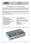
Octal Serial Communication Interface (OSCI)
The OSCI module is a PC/104-Plus Card that provides 8 free selectable serial interfaces, either RS232 or
RS485 / RS422 - interface , to any PC/104-Plus system.
There are 2 standard variants of the OSCI module available:
OSCI-8MIX:
Standard PC/104-Plus card for all PC/104-Plus compatible PCs. 8 free selectable
RS232 or RS485 full or half duplex interfaces. Two self configurable interface cables
are included to connecting the on board headers to standard D-SUB 9 pin
connectors.
OSCI-6MIX2G: Standard PC/104-Plus card for all PC/104-Plus compatible PCs. 6 free selectable
RS232 or RS485 full or half duplex interfaces. Galvanic isolation (500Vrms) on the
first 2 serial interfaces (interfaces used as RS485 / RS422). Two self configurable
interface cables are included to connecting the on board headers to standard D-SUB
9 pin connectors.
At the publication date of this manual, the following MPL products are supported:
• PIP405, PIP5, PIP6, PIP7, PIP8
• MIP405
Features
• PC/104-Plus universal board, PC/104-Plus Compliant
• Up to 8 serial RS232 or RS485 / RS422 interfaces
• Mixed port configuration easy selectable over software
• Standard Baud rate up to 250 kBaud
• RS485 interfaces up to 60 V fail save (optional)
• RS485 interfaces up to 6.25 Mbaud (optional)
• Galvanic Isolation on two RS485 lines (optional)
• +/- 15 kV ESD protection
• Only 5 V power supply needed
• For bigger order quantities several assembly options are available. Please feel free to contact MPL AG
for further information.
2004 by MPL AG, Switzerland
1
MEH-10101-001 Rev. A
OSCI
User Manual
TABLE OF CONTENTS
1. INTRODUCTION...................................................................................................................... 4
1.1
1.2
1.3
1.4
1.5
1.6
1.7
ABOUT THIS MANUAL ................................................................................................................. 4
SAFETY PRECAUTIONS AND HANDLING .................................................................................. 4
ELECTROSTATIC DISCHARGE (ESD) PROTECTION ................................................................. 4
EQUIPMENT SAFETY................................................................................................................... 4
RELATED DOCUMENTATION ...................................................................................................... 5
ORDERING INFORMATION .......................................................................................................... 5
REVISION HISTORY ..................................................................................................................... 5
2. SPECIFICATIONS ................................................................................................................... 6
2.1
2.2
2.3
PC104 / PC/104-PLUS INTERFACE.............................................................................................. 6
SERIAL INTERFACES .................................................................................................................. 6
ENVIRONMENT ............................................................................................................................ 6
3. PARTS LOCATION.................................................................................................................. 7
3.1
3.2
3.3
OSCI-8MIX .................................................................................................................................... 7
OSCI-6MIX2G................................................................................................................................ 8
OSCI-4MIX .................................................................................................................................... 9
4. CONNECTORS...................................................................................................................... 10
4.1
J12 / J14 PC104 CONNECTORS ................................................................................................ 10
4.2
J13 PC/104-PLUS CONNECTOR ................................................................................................ 11
4.3
SERIAL INTERFACE CONNECTORS......................................................................................... 12
4.4
OSCI INTERFACE CABLES........................................................................................................ 14
4.4.1
CONFIGURATION OF THE CABLES.................................................................................... 14
4.4.2
SERIAL INTERFACE D-SUB CONNECTORS....................................................................... 14
5. CONFIGURATION ................................................................................................................. 15
5.1
PC/104-PLUS MODULE SLOT SELECTION ............................................................................... 15
5.2
RS485 / RS232 INTERFACE SELECTION .................................................................................. 15
5.2.1
LINUX ................................................................................................................................... 15
5.2.2
VxWORKS ............................................................................................................................ 15
5.2.3
WINDOWS............................................................................................................................ 15
5.3
CABLE CONFIGURATION IN RS485 / RS422 MODE ................................................................. 15
5.3.1
HALF AND FULL DUPLEX.................................................................................................... 15
5.3.2
TERMINATION ..................................................................................................................... 15
6. OPERATION.......................................................................................................................... 16
6.1
RS232 BASICS............................................................................................................................ 16
6.2
RS422 / RS485 BASICS .............................................................................................................. 16
6.2.1
TOPOLOGIES ACCORDING TO RS422 AND RS485 ........................................................... 16
6.2.2
SOME IMPORTANT VALUES............................................................................................... 16
7. DRIVERS ............................................................................................................................... 17
7.1
LINUX.......................................................................................................................................... 17
7.1.1
DRIVER INSTALLATION ...................................................................................................... 17
7.1.2
DRIVER CONFIGURATION .................................................................................................. 17
7.1.3
DRIVER IOCTRLS ................................................................................................................ 17
2004 by MPL AG, Switzerland
2
MEH-10101-001 Rev. A
OSCI
User Manual
7.2
VXWORKS .................................................................................................................................. 17
7.3
WINDOWS................................................................................................................................... 17
7.3.1
DRIVER INSTALLATION ...................................................................................................... 17
7.3.1.1
WINDOWS NT................................................................................................................... 17
7.3.1.2
WINDOWS 2000................................................................................................................ 18
7.3.1.3
WINDOWS XP................................................................................................................... 22
7.3.2
DRIVER CONFIGURATION .................................................................................................. 26
7.3.3
DRIVER IOCTRLS ................................................................................................................ 27
7.3.3.1
IOCTRL DEFINITION ........................................................................................................ 27
7.3.3.2
IOCTRL EXAMPLE............................................................................................................ 28
7.4
TESTED OPERATING-SYSTEMS ............................................................................................... 28
8. MOUNTING............................................................................................................................ 29
8.1
8.2
8.3
PARTS NEEDED FOR MOUNTING............................................................................................. 29
MOUNTING DESCRIPTION......................................................................................................... 29
MECHANICAL DIMENSIONS...................................................................................................... 29
9. COPYRIGHT .......................................................................................................................... 32
10. DISCLAIMER ......................................................................................................................... 32
11. SUPPORT.............................................................................................................................. 32
2004 by MPL AG, Switzerland
3
MEH-10101-001 Rev. A
OSCI
User Manual
1. INTRODUCTION
1.1 ABOUT THIS MANUAL
This manual provides all the information necessary to handle and configure the OSCI Module.
The manual is written for technical personnel responsible for integrating and using the OSCI into their
systems.
1.2 SAFETY PRECAUTIONS AND HANDLING
For personal safety and safe operation of the OSCI module, follow all safety procedures described here and
in other sections of the manual.
• Remove power from the system before installing (or removing) the OSCI to prevent the possibility of
personal injury (electrical shock) and / or damage to the hardware.
• Handle the product carefully; i.e. dropping or mishandling the OSCI can cause damage to assemblies and
components.
• Do not expose the OSCI to moisture.
• Read and follow all the instructions and warnings described herein.
• Keep the OSCI module away from all sources of liquids, such as coffee cups, drinking glasses, washing
facilities etc.
• Keep this manual available for reference.
For your protection and that of the OSCI module disconnect the power input of the used host system
immediately if any of the following conditions exists:
• The power input cable has been damaged.
• Something has been spilt onto the modules.
• The OSCI module has been damaged in any way, e.g. through dropping.
• You suspect that any module requires servicing or repair.
NOTE:
There are no user-serviceable components on the OSCI.
1.3 ELECTROSTATIC DISCHARGE (ESD) PROTECTION
Various electrical components within the product are sensitive to static and electrostatic discharge (ESD).
Even a non-sensible static discharge can be sufficient to destroy or degrade a component's operation!
Therefor handle the module only in an ESD protected environment.
The serial interfaces are all protected against electrostatic discharge but only when the OSCI module is
proper installed into a system and the system has a good Ground connection.
1.4 EQUIPMENT SAFETY
Great care is taken by MPL that all its products are thoroughly and rigorously tested before leaving the
factory to ensure that they are fully operational and conform to specification. However, no matter how reliable
a product, there is always the remote possibility that a defect may occur. The occurrence of a defect on this
device may, under certain conditions, cause a defect to occur in adjoining and/or connected equipment. It is
your responsibility to protect such equipment when installing this device. MPL accepts no responsibility
whatsoever for such defects, however caused.
2004 by MPL AG, Switzerland
4
MEH-10101-001 Rev. A
OSCI
User Manual
1.5 RELATED DOCUMENTATION
The following documents are related to this manual.
Reference
[1]
[2]
[3]
Description
XR17D158 Datasheet Rev. 1.1.0
PC/104-PLUS Spec. Rev. 2.0
PCI Local Bus Specification Rev. 2.2.
Available from
Exar Corporation:
www.exar.com
PC/104 Embedded Consortium: www.pc104.org
PCI-SIG:
www.pcisig.com
1.6 ORDERING INFORMATION
Product Name
Interface Options
Selectable
RS232 or RS485/422
OSCI-8MIX*
OSCI-8RS2
OSCI-8RS4
OSCI-6MIX-2G
OSCI-6RS2-2G
OSCI-6RS4-2G
OSCI-4MIX*
OSCI-4RS2
OSCI-4RS4
OSCI-3MIX-1G
OSCI-3RS2-1G
OSCI-3RS4-1G
*
Fix
RS232
Fix
RS485/422
Galvanic isolated
RS485/422
8
8
8
6
6
6
2
2
2
4
4
4
3
3
3
1
1
1
Available from stock
1.7 REVISION HISTORY
This manual reflects the revision A of the OSCI module.
Publication Date : 02. June 2004
Manual
Revision
A
Date
Description
02.06.2004
Initial Write
2004 by MPL AG, Switzerland
5
MEH-10101-001 Rev. A
OSCI
User Manual
2. SPECIFICATIONS
2.1 PC104 / PC/104-PLUS INTERFACE
•
•
•
•
•
33MHz, 32Bit
Accepts 3.3V and 5V PCI IO voltage
Needs only 5V power supply from PC/104-Plus bus
Power requirement (OSCI with 8 serial interfaces):
• OSCI-8MIX:
5 V:
65 mA (Interfaces disabled)
110 mA (all RS485 interfaces enabled)
130 mA (all RS232 interfaces enabled)
• OSCI-6MIX2G:
5 V:
110 mA (Interfaces disabled)
140 mA (all RS485 interfaces enabled)
140 mA (all RS232 interfaces enabled)
Supports parallel PCI Interrupts
2.2 SERIAL INTERFACES
•
•
•
•
•
•
•
Up to 8 Ports
Software selectable RS232 or RS485 / RS422 full or half duplex interface
+/-15 kV ESD protection
250kBaud standard baud rate for RS232 and RS485 / RS422
Galvanic isolation on two RS485 interfaces (port 0 and 1) until 500 Vrms (optional)
RS485 / RS422 until 60 V fail save available (optional)
RS485 / RS422 until 6.25 MBaud available (optional)
2.3 ENVIRONMENT
•
•
•
Temperature range 0 °C..70 °C
Industrial temperature range -40 °C .. +85 °C available
Relative humidity 5 % .. 95 %, not condensing
2004 by MPL AG, Switzerland
6
MEH-10101-001 Rev. A
OSCI
User Manual
3. PARTS LOCATION
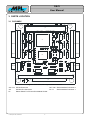
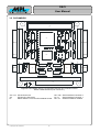
3.1 OSCI-8MIX
D1 C11
C13
C62
C79
D30
M2
M3
J13
50
C31
U1
U4
R5
U6
17
C86
C95
U17
U20
Port 6
U15
U9
C58
C81
U16
C40 C46 C28 C59
C76 R25
C77 R26
U18
C67
C68
J15
C69
C60 C70
C82
R27
R20
C78
R22
R21
R23
U10
X1
C52
U19
C96
C92 C93 C94
C16
C80
R29
C9 C10
U3
C8
Port 3
U5
R6
C3
C7
U2
C57
C74
C89 C90 C91
C6
J1
U14
R28
C15
C35
C85
C66
C5
R3
C2
C47 C64 C75 C56
C87 C88
C14
C43
C63 C65
C4
R11 C44 R12 R13 R14 C25
C36 C38 C34 C20 C37 C39 C21 R17 C22 C23 C24 R8 R9
R15
C17
R16
C1
C18 C19
Port 7
Port 5
50
A30
A1
C97
J26
Port 4
U21
Port 2
U22
17
C71 R24
C53
10
R1
R2
C83
C49
U11
U13
C26 C29 C32
U8
U12
C27 C30 C33 R10
B1
C84
10
R31
J25
R30
1
R19 C51 C55 C73
B32
J12
A32
A1
C19
C0
S1
R7
R4
M1
Port 0
C98
C42
C50 C54 C72
C45
J17
J16
J18
J19
J20
J21
J22
J23
J24
D4
U7
C61
D3
C12
1
C48
C41
R18
D2
D1
Port 1 J2
J3
J4
J5
J6
J8
J7
J9
J10
J11
J14
D0
D19
M4
S1=OFF/S2 =OFF: M ODULE =1, OFF/ON: 2, ON/OFF: 3 , ON /ON : 4
Figure 1: OSCI-8MIX, With 8 Type Selectable Interfaces
J12 / J14 PC104 Connector
J13
PC/104-Plus Connector
S1
Select-Switch For PC/104-Plus Module Socket
2004 by MPL AG, Switzerland
7
J25 / J26 Serial Interface Connector 0
J2 / J1
Serial Interface Connector 1
MEH-10101-001 Rev. A
OSCI
User Manual
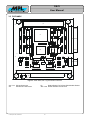
3.2 OSCI-6MIX2G
D1 C11
C13
C62
C79
D30
M2
M3
J13
50
C31
U1
U4
R5
17
C95
U17
U20
Port 6
U15
U9
C58
C81
U16
C40 C46 C28 C59
C76 R25
C77 R26
C67
C68
J15
C69
C60 C70
R27
R20
C78
R22
R21
R23
U10
U18
X1
C52
C82
U19
C96
C92 C93 C94
U6
C57
C86
C89 C90 C91
C16
U14
C80
R29
C9 C10
U3
C8
Port 3
U5
R6
C3
C7
U2
C85
C74
R28
C6
J1
C47 C64 C75 C56
C66
C5
R3
C2
C15
C43
C35
C87 C88
C14
C63 C65
C4
R11 C44 R12 R13 R14 C25
C36 C38 C34 C20 C37 C39 C21 R17 C22 C23 C24 R8 R9
R15
C17
R16
C1
C18 C19
Port 7
Port 5
50
A30
A1
C97
J26
Port 4
U21
Port 2
U22
17
C71 R24
C53
10
R1
C48
C41
R2
C83
U11
U13
T1
C26 C29 C32
U8
U12
C27 C30 C33 R10
B1
T2
J25
Port 0
C98
C12
C42
1
C50 C54 C72
C45
D4
C49
10
R31
D3
Port 1 J2
R18
D2
D1
U7
C61
C84
R30
1
R19 C51 C55 C73
B32
J12
A32
A1
C19
C0
S1
R7
R4
M1
J14
D0
D19
M4
S1=OFF/S2 =OFF: M ODULE =1, OFF/ON: 2, ON/OFF: 3 , ON /ON : 4
Figure 2: OSCI-6MIX2G, With 6 Type Selectable Interfaces And 2 Galvanic Isolated
RS422 / RS485 Interfaces (Port 0 And Port 1)
J12 / J14 PC104 Connector
J13
PC/104-Plus Connector
S1
Select-Switch For PC/104-Plus Module Socket
2004 by MPL AG, Switzerland
8
J25 / J26 Serial Interface Connector 0
J2 / J1
Serial Interface Connector 1
J25 / J2 500Vrms Galvanic Isolation
MEH-10101-001 Rev. A
OSCI
User Manual
3.3 OSCI-4MIX
D1 C11
C13
C62
C79
D30
M2
M3
J13
50
50
A30
A1
C18 C19
U4
R5
C86
C95
U17
U20
Port 3
U15
U9
C58
C81
U16
C40 C46 C28 C59
C76 R25
C77 R26
C67
C68
J15
C69
C60 C70
R27
R20
C78
R22
R21
R23
U10
U18
X1
C52
C82
U19
C96
C92 C93 C94
17
C80
C89 C90 C91
C9 C10
U6
C57
C74
R29
C8
R6
U3
C16
U14
R28
C6 C7
C3
U5
C35
C85
C66
C5
U2
R3
C2
C15
C47 C64 C75 C56
C87 C88
U1
C14
C43
C63 C65
C4
R11 C44 R12 R13 R14 C25
C36 C38 C34 C20 C37 C39 C21 R17 C22 C23 C24 R8 R9
R15
C17
R16
C1
C31
C97
J26
Port 2
U21
Port 1
U22
17
C71 R24
C53
10
R1
R2
C48 C61
C41
C83
U11
U13
C26 C29 C32
U8
U12
C27 C30 C33 R10
B1
C84
J25
R30
1
R19 C51 C55 C73
B32
J12
A32
A1
C19
C0
S1
R7
R4
M1
Port 0
C98
C12
C42
C50 C54 C72
C45
10
R31
D4
C49
J17
J16
J18
J19
J20
J21
J22
J23
J24
D3
U7
R18
D1
D2
1
J3
J4
J5
J6
J8
J7
J9
J10
J11
J14
D0
D19
M4
S1=OFF/S2=OFF: MODULE=1, OFF/ON: 2, ON/OFF: 3, ON/ON: 4
Figure 3: OSCI-4MIX, With 4 Type Selectable Interfaces
J12 / J14 PC104 Connector
J13
PC/104-Plus Connector
2004 by MPL AG, Switzerland
S1
Select-Switch For PC/104-Plus Module Socket
J25 / J26 Serial Interface Connector 0
9
MEH-10101-001 Rev. A
OSCI
User Manual
4. CONNECTORS
4.1 J12 / J14 PC104 CONNECTORS
The PC104 connector is a standard 2.54mm stack through connector. Only the power pins are used on this
connector. All other pins are only for stacking trough the PC104 signals.
Number
0
1
2
3
4
5
6
7
8
9
10
11
12
13
14
15
16
17
18
19
20
21
22
23
24
25
26
27
28
29
30
31
32
Row A
-NC (/IOCHCK)
NC (SD7)
NC (SD6)
NC (SD5)
NC (SD4)
NC (SD3)
NC (SD2)
NC (SD1)
NC (SD0)
NC (IOCHRDY)
NC (AEN)
NC (SA19)
NC (SA18)
NC (SA17)
NC (SA16)
NC (SA15)
NC (SA14)
NC (SA13)
NC (SA12)
NC (SA11)
NC (SA10)
NC (SA9)
NC (SA8)
NC (SA7)
NC (SA6)
NC (SA5)
NC (SA4)
NC (SA3)
NC (SA2)
NC (SA1)
NC (SA0)
GND
Row B
-GND
NC (RSTDRV)
+5V
NC (IRQ9)
NC (-5V)
NC (DRQ2)
NC (-12V)
NC (/ENDXFR)
NC (+12V)
NC
NC (/SMEMW)
NC (/SMEMR)
NC (/IOW)
NC (/IOR)
NC (/DACK3)
NC (DRQ3)
NC (/DACK1)
NC (DRQ1)
NC (/REFRESH)
NC (SYSCLK)
NC (IRQ7)
NC (IRQ6)
NC (IRQ5)
NC (IRQ4)
NC (IRQ3)
NC (/DACK2)
NC (TC)
NC (BALE)
+5V
NC (OSC)
GND
GND
Row C
GND
NC (/SBHE)
NC (LA23)
NC (LA22)
NC (LA21)
NC (LA20)
NC (LA19)
NC (LA18)
NC (LA17)
NC (/MEMR)
NC (/MEMW)
NC (SD8)
NC (SD9)
NC (SD10)
NC (SD11)
NC (SD12)
NC (SD13)
NC (SD14)
NC (SD15)
NC
--------------
Row D
GND
NC
NC (/IOCS16)
NC (IRQ10)
NC (IRQ11)
NC (IRQ12)
NC (IRQ15)
NC (IRQ14)
NC (/DACK0)
NC (DRQ0)
NC (/DACK5)
NC (DRQ5)
NC (/DACK6)
NC (DRQ6)
NC (/DACK7)
NC (DRQ7)
+5V
NC (/MASTER)
GND
GND
--------------
Pin Out
AB
1
DC
0
19
32
Figure 4: PC104 connector
Table 1: PC104 Connector Pin Out
Note:
• Only the shaded pins are connected, all other pins are not connected on the OSCI PCB.
2004 by MPL AG, Switzerland
10
MEH-10101-001 Rev. A
OSCI
User Manual
4.2 J13 PC/104-PLUS CONNECTOR
The PC/104-Plus connector is a standard 2mm stack through connector.
Number
1
2
3
4
5
6
7
8
9
10
11
12
13
14
15
16
17
18
19
20
21
22
23
24
25
26
27
28
29
30
Row A
GND (5V Key)
+5V
AD5
C/BE0
GND
AD11
AD14
NC (+3,3V)
SERR
GND
STOP
NC (+3,3V)
FRAME
GND
AD18
AD21
NC (+3,3V)
IDSEL0
AD24
GND
AD29
+5V
NC (REQ0)
GND
NC (GNT1)
+5V
CLK2
GND
NC (+12V)
NC (-12V)
Row B
NC
AD2
GND
AD7
AD9
+5V
AD13
C/BE1
GND
PERR
NC (+3,3V)
TRDY
GND
AD16
NC (+3,3V)
AD20
AD23
GND
C/BE3
AD26
+5V
AD30
GND
NC (REQ2)
+5V
CLK0
+5V
INTD
INTA
NC
Row C
+5V
AD1
AD4
GND
AD8
AD10
GND
AD15
NC (SBO)
NC (+3,3V)
NC (LOCK)
GND
IRDY
NC (+3,3V)
AD17
GND
AD22
IDSEL1
+5V
AD25
AD28
GND
NC (REQ1)
+5V
NC (GNT2)
GND
CLK3
+5V
INTB
NC
Row D
Pin Out
AD0
+5V
AD3
AD6
GND
GND (M66EN)
ABCD
1
AD12
NC (+3,3V)
PAR
NC (SDONE)
GND
DEVSEL
NC (+3,3V)
C/BE2
GND
AD19
NC (+3,3V)
GND
IDSEL2
IDSEL3
AD27
AD31
30
+5V
NC (GNT0)
Figure 5: PC/104-Plus connector
GND
CLK1
GND
RST
INTC
GND (3.3V Key)
Table 2: PC/104-Plus Connector Pin Out
Note:
• All the shaded signals are not connected on the OSCI PCB.
2004 by MPL AG, Switzerland
11
MEH-10101-001 Rev. A
OSCI
User Manual
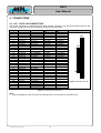
4.3 SERIAL INTERFACE CONNECTORS
The two serial interface connectors (standard 2.54mm headers) distribute the serial interface signals to the
interface cables that support the standard 9 pin D-SUB connectors for serial interfaces.
Pin
#
1
2
3
4
5
6
7
8
9
10
11
12
13
14
15
16
17
18
19
20
21
22
23
24
25
26
27
28
29
30
31
32
33
34
35
36
37
38
39
40
41
42
43
44
45
46
47
48
49
50
RS232
Signal
DCD0
DSR0
RxD0
RTS0
TxD0
CTS0
DTR0
RI0
GND
GND
NC
NC
NC
NC
NC
NC
DCD2
DSR2
RxD2
RTS2
TxD2
CTS2
DTR2
RI2
GND
GND
GND
GND
DCD4
DSR4
RxD4
RTS4
TxD4
CTS4
DTR4
RI4
GND
GND
GND
GND
DCD6
DSR6
RxD6
RTS6
TxD6
CTS6
DTR6
RI6
GND
GND
RS232 Signal Description
Data Carrier Detect Port 0
Data Set Ready Port 0
Receive Data Port 0
Request To Send Port 0
Transmit Data Port 0
Clear To Send Port 0
Data Terminal Ready Port 0
Ring Indicator Port 0
Ground
Ground
No contact available
No contact available
No contact available
No contact available
No contact available
No contact available
Data Carrier Detect Port 2
Data Set Ready Port 2
Receive Data Port 2
Request To Send Port 2
Transmit Data Port 2
Clear To Send Port 2
Data Terminal Ready Port 2
Ring Indicator Port 2
Ground
Ground
Ground
Ground
Data Carrier Detect Port 4
Data Set Ready Port 4
Receive Data Port 4
Request To Send Port 4
Transmit Data Port 4
Clear To Send Port 4
Data Terminal Ready Port 4
Ring Indicator Port 4
Ground
Ground
Ground
Ground
Data Carrier Detect Port 6
Data Set Ready Port 6
Receive Data Port 6
Request To Send Port 6
Transmit Data Port 6
Clear To Send Port 6
Data Terminal Ready Port 6
Ring Indicator Port 6
Ground
Ground
RS485
Signal
NC
NC
Rx+0
Rx-0
Tx+0
Tx-0
NC
NC
GND
GND
NC
NC
NC
NC
NC
NC
NC
NC
Rx+2
Rx-2
Tx+2
Tx-2
NC
NC
GND
GND
GND
GND
NC
NC
Rx+4
Rx-4
Tx+4
Tx-4
NC
NC
GND
GND
GND
GND
NC
NC
Rx+6
Rx-6
Tx+6
Tx-6
NC
NC
GND
GND
RS485/422 Signal
Description
Not Connected
Not Connected
Receive Data +
Receive Data Transmit Data +
Transmit Data Not Connected
Not Connected
Ground
Ground
No contact available
No contact available
No contact available
No contact available
No contact available
No contact available
Not Connected
Not Connected
Receive Data +
Receive Data Transmit Data +
Transmit Data Not Connected
Not Connected
Ground
Ground
Ground
Ground
Not Connected
Not Connected
Receive Data +
Receive Data Transmit Data +
Transmit Data Not Connected
Not Connected
Ground
Ground
Ground
Ground
Not Connected
Not Connected
Receive Data +
Receive Data Transmit Data +
Transmit Data Not Connected
Not Connected
Ground
Ground
Pin Out
2
J25
1
10 18
9
17
J26
50
49
Figure 6: Serial Interface Connector 0
Table 3: Serial Interface Connector 0 Pin Out
Note:
●
•
All interface signals are ESD protected.
In case of galvanic isolation the galvanic isolated interface is on the pins 1..10.
2004 by MPL AG, Switzerland
12
MEH-10101-001 Rev. A
OSCI
User Manual
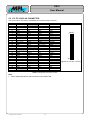
The contacts are so arranged that the same interface cable can be used on both sides.
Pin
#
1
2
3
4
5
6
7
8
9
10
11
12
13
14
15
16
17
18
19
20
21
22
23
24
25
26
27
28
29
30
31
32
33
34
35
36
37
38
39
40
41
42
43
44
45
46
47
48
49
50
RS232
Signal
DCD1
DSR1
RxD1
RTS1
TxD1
CTS1
DTR1
RI1
GND
GND
NC
NC
NC
NC
NC
NC
DCD3
DSR3
RxD3
RTS3
TxD3
CTS3
DTR3
RI3
GND
GND
GND
GND
DCD5
DSR5
RxD5
RTS5
TxD5
CTS5
DTR5
RI5
GND
GND
GND
GND
DCD7
DSR7
RxD7
RTS7
TxD7
CTS7
DTR7
RI7
GND
GND
RS485 Signal Description
Data Carrier Detect Port 1
Data Set Ready Port 1
Receive Data Port 1
Request To Send Port 1
Transmit Data Port 1
Clear To Send Port 1
Data Terminal Ready Port 1
Ring Indicator Port 1
Ground
Ground
No contact available
No contact available
No contact available
No contact available
No contact available
No contact available
Data Carrier Detect Port 3
Data Set Ready Port 3
Receive Data Port 3
Request To Send Port 3
Transmit Data Port 3
Clear To Send Port 3
Data Terminal Ready Port 3
Ring Indicator Port 3
Ground
Ground
Ground
Ground
Data Carrier Detect Port 5
Data Set Ready Port 5
Receive Data Port 5
Request To Send Port 5
Transmit Data Port 5
Clear To Send Port 5
Data Terminal Ready Port 5
Ring Indicator Port 5
Ground
Ground
Ground
Ground
Data Carrier Detect Port 7
Data Set Ready Port 7
Receive Data Port 7
Request To Send Port 7
Transmit Data Port 7
Clear To Send Port 7
Data Terminal Ready Port 7
Ring Indicator Port 7
Ground
Ground
RS485
Signal
NC
NC
Rx+1
Rx-1
Tx+1
Tx-1
NC
NC
GND
GND
NC
NC
NC
NC
NC
NC
NC
NC
Rx+3
Rx-3
Tx+3
Tx-3
NC
NC
GND
GND
GND
GND
NC
NC
Rx+5
Rx-5
Tx+5
Tx-5
NC
NC
GND
GND
GND
GND
NC
NC
Rx+7
Rx-7
Tx+7
Tx-7
NC
NC
GND
GND
RS485/422 Signal
Description
Not Connected
Not Connected
Receive Data +
Receive Data Transmit Data +
Transmit Data Not Connected
Not Connected
Ground
Ground
No contact available
No contact available
No contact available
No contact available
No contact available
No contact available
Not Connected
Not Connected
Receive Data +
Receive Data Transmit Data +
Transmit Data Not Connected
Not Connected
Ground
Ground
Ground
Ground
Not Connected
Not Connected
Receive Data +
Receive Data Transmit Data +
Transmit Data Not Connected
Not Connected
Ground
Ground
Ground
Ground
Not Connected
Not Connected
Receive Data +
Receive Data Transmit Data +
Transmit Data Not Connected
Not Connected
Ground
Ground
Pin Out
49
50
J1
17
9
J2
18 10
1
2
Figure 7: Serial Interface Connector 1
Table 4: Serial Interface Connector 1 Pin Out
Note:
• All interface signals are ESD protected.
• In case of galvanic isolation the galvanic isolated interface is on the pins 1..10.
• In case of OSCI-4xxx or –3xxx the Serial Interface Connector 1 is not used. All the interface signals are
on connector 0 (please refer to chapter 3.3).
2004 by MPL AG, Switzerland
13
MEH-10101-001 Rev. A
OSCI
User Manual
4.4 OSCI INTERFACE CABLES
The PC/104-Plus Card has not enough physical space to support the serial interfaces with standard D-SUB
connectors. There are two interface cables delivered with the OSCI to connect the on board headers with the
standard 9 pin D-SUB connectors.
4.4.1 CONFIGURATION OF THE CABLES
Pin 1
Identifier
Flat Ribbon
Cable Pin 1
Flat Ribbon
Cable Pin 17
D-SUB Connector
Serial Port 0 or 1
Pin 1
Connected
Pin1..Pin9
Unconnected
Pin10..Pin16
D-SUB Connector
Serial Port 2 or 3
Pin 1
Connected
Pin17..Pin25
50 Pin Flat Cable
Connector
Unconnected Pin26..Pin28
D-SUB Connector
Serial Port 4 or 5
Pin 1
Connected
Pin29..Pin37
Unconnected Pin38..Pin40
Connected
Pin41..Pin49
D-SUB Connector
Serial Port 6 or 7
Pin 1
Unconnected Pin50
Flat Ribbon
Cable Pin 29
Flat Ribbon
Cable Pin 41
Figure 8: Flat Cable With Header Connector And 9 Pin D-SUB Connectors
4.4.2 SERIAL INTERFACE D-SUB CONNECTORS
Pin
Number
1
2
3
4
5
6
7
8
9
Signal
RS232
DCD
RxD
TxD
DTR
GND
DSR
RTS
CTS
RI
Description
RS232
Data Carrier Detect
Receive Data
Transmit Data
Data Terminal Ready
Ground
Data Set Ready
Request To Send
Clear To Send
Ring Indicator
Signal
RS485/422
NC
Rx+
Tx+
NC
GND
NC
RxTxNC
Description
RS485/422
Not Connected
Receive Data +
Transmit Data +
Not Connected
Ground
Not Connected
Receive Data Transmit Data Not Connected
Pin Out
1
5
6
9
Figure 9: Serial Interface Connector
Table 5: Serial Interface D-SUB Connector Pin Out
Note:
• All interface signals are ESD protected on the OSCI.
• In case of RS485 half duplex mode the signals Rx+ / Tx+ and Rx- / Tx- must be connected
together in the cable connector case.
2004 by MPL AG, Switzerland
14
MEH-10101-001 Rev. A
OSCI
User Manual
5. CONFIGURATION
1
2
O
N
5.1 PC/104-PLUS MODULE SLOT SELECTION
Figure 10: Module Slot Selection Slide Switch S1
S1_1
S1_2
OFF
OFF
ON
ON
OFF
ON
OFF
ON
PC/104-Plus Module
Slot
0
1
2
3
Table 6: DIP-Switch S1 Settings
The OSCI needs no PCI REQ/GNT pair. It can used in a standard PC/104-Plus stack at any position.
In the MPL’s PIPx family only PC/104-Plus Slot 0 and Slot 1 are supported.
5.2 RS485 / RS232 INTERFACE SELECTION
The selection of the interface type is made via the hardware driver, either with IoCtrls or at Boot Time.
5.2.1 LINUX
Please refer to the chapter 7.1.2 for further information.
5.2.2 VxWORKS
Please refer to the chapter 7.2 for further information.
5.2.3 WINDOWS
In the Windows operating systems you can easy select the function you want in the System Control panel
under OSCI Configuration. Please refer to the chapter 7.3.2 for further information.
5.3 CABLE CONFIGURATION IN RS485 / RS422 MODE
5.3.1 HALF AND FULL DUPLEX
For half duplex mode it’s needed that you connect in your cable connector the Tx+ / Rx+ signals and the Rx/ Tx- signals together. So you have a 2 wire cable.
In full duplex mode you have a 4 wire cable and you must not connect any signals together.
NOTE:
In half duplex mode connect the Tx+ / Rx+ signals and the Rx- / Txsignals together.
5.3.2 TERMINATION
If the OSCI is at the end of your half duplex network you have to terminate in the cable connector the
differential transceiver lines Rx+/Tx+ to Rx-/Tx- with 120Ω.
For full duplex mode you must have a cable with 4 wires. If the OSCI is at the end of your 4 wire serial
network you have to terminate the Rx+ /Rx- signals with either 100Ω or 120Ω.
NOTE:
If the OSCI is at the end of your serial network terminate the
Receiver input with 100Ω or 120Ω
2004 by MPL AG, Switzerland
15
MEH-10101-001 Rev. A
OSCI
User Manual
6. OPERATION
6.1 RS232 BASICS
The full name of this interface is “Interface Between Data Terminal Equipment [DTE, e.g. PC] and Data
Circuit-Terminating Equipment [DCE, e.g. modem] Employing Serial Binary Data Interchange”.
The maximum driver load capacitance is specified as 2500pF. This allows a cable length of about 15m..20m,
dependent on the cable quality. The RS232 interface don’t need any termination resistors at any end of the
transmission line.
The signal levels allowed on driver output are:
High level or 1 or Mark:
-5V..-15V
Low level or 0 or Space:
5V..15V
The signal levels allowed on receiver input are:
High level or 1 or Mark:
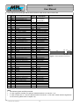
-3V..-25V
Low level or 0 or Space:
3V..25V
The driver interface devices used on OSCI have a maximum withstand rating for receiver and transmitter
pins of +/- 30V.
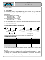
6.2 RS422 / RS485 BASICS
6.2.1 TOPOLOGIES ACCORDING TO RS422 AND RS485
120 Ohm
120 Ohm
100 Ohm
Driver
Driver
Receiver
Receiver
Receiver
Driver
Driver
Receiver
Receiver
2..32 Generator / Receiver Pairs
1..10 Receiver
Figure 11: RS422 Topology, Simplex Operation
Figure 12: RS485 Topology, Half Duplex Operation
2 Simplex lines in opposite direction (each with one receiver) result in a full duplex line.
6.2.2 SOME IMPORTANT VALUES
Max. Common Mode Voltage
Receiver Input Impedance
Minimum Generator Load
Generator Short Circuit Current
Signal High Level (Rx+ - Rx-)
Signal Low Level (Rx+ - Rx-)
Number Of Receivers
Max. Cable Length
Termination Resistor
RS422
RS485
-7V..+7V
-7V..+12V
Min. 4kΩ
Min. 12kΩ
100Ω
60Ω
<150mA to GND <250mA to –7V..+12V
> 200mV
< -200mV
1..10
1..32
About 1200m (also see below)
100Ω
120Ω
OSCI Differences
+/-30V
5kΩ
1..30
The OSCI hardware supports the stronger requirements of the RS485 standard. Except for the receiver input
impedance. That reduces the maximum number of receivers that can be connected to one driver. The
maximum allowed load with RS485 receivers (without the termination) is 375Ω (12kΩ 32 times in parallel) for
a driver. So if all other receivers are in the RS485 specification you can only connect 30 receivers to a driver
and not 32.
A rule of thumb says the product of data rate in Bits/s and the line length in meter must be <= 108 (means
e.g. 1Mbit/s with 100m or 100kbit/s with 1000m), but this is depending on the cable quality. Also it is not true
for cables longer than about 1000m.
The longer the line the greater the possibility of high common mode voltages. In some arrangements it is
better to use an interface with galvanic isolation for long connection lines.
2004 by MPL AG, Switzerland
16
MEH-10101-001 Rev. A
OSCI
User Manual
7. DRIVERS
The OSCI needs a special driver from MPL AG.
7.1 LINUX
There is an OSCI Linux driver for the old driver model and also one for the new driver model in kernel 2.6
available. With the old driver model only RS232 interfaces are supported until now.
7.1.1 DRIVER INSTALLATION
All the Files you need, you will find on the MPL AG’s homepage www.mpl.ch.
The MPL OSCI driver is provided as a patch against the official Linux-2.6.x kernel source, so in order to use
the driver you have to compile and install a new kernel and modules on your Linux machine.
The following is a quick step guide for this task:
• Download and/or install Linux-2.6.x kernel source on your machine
• Download the file "mpl_osci.patch.bz2" to machine
• Patch the kernel using "bunzip2 -c mpl_osci.patch.bz2 | patch -Ep1"
• Configure the kernel with support for MPL OSCI
• After a successful "make bzImage modules", install the new kernel and modules
• Reboot to use the new kernel or load the module using "modprobe mpl_osci"
7.1.2 DRIVER CONFIGURATION
(Almost) all driver configuration is done using IOCTLs. Some of them are OSCI specific (for more info, see
chapter 7.1.3), others are common for a whole class of devices.
7.1.3 DRIVER IOCTRLS
There are a number of OSCI specific IOCTLs. Please take a look at the "oscimode.c" file to get an idea on
how to use them.
Please note that the interface of the OSCI specific IOCTL calls is not stable yet.
7.2 VXWORKS
A VxWorks driver is in the queue.
7.3 WINDOWS
There are OSCI drivers for WinNT4.0, Win2000 and WinXP available. A WinCE driver is in the queue.
NOTE:
The WinNT4.0 driver supports only 1 OSCI card!
The Win2000 and WinXP driver supports power management and disables the transceiver chips if the ports
are not opened with software.
7.3.1 DRIVER INSTALLATION
All the drivers and install programs you will find on the MPL AG’s homepage www.mpl.ch.
7.3.1.1 WINDOWS NT
To install the driver and a set-up tool, you only have to execute the driver install program osciNTxx.exe (xx
stays for the version number).
Then the system ask for a reboot. Click Yes and after the Reboot the OSCI can be configured with the OSCI
Configuration Control Panel Applet. For more information about OSCI configuration please refer to the
chapter 7.3.2.
NOTE:
It’s important that you configure each ports interface type, else the
ports stay in disable mode and nothing can be transmitted!
2004 by MPL AG, Switzerland
17
MEH-10101-001 Rev. A
OSCI
User Manual
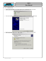
7.3.1.2 WINDOWS 2000
•
•
Install the OSCI hardware in your system (please refer to chapter 8 for more information).
At the next boot time Windows 2000 will find a new PCI Serial Port Device.
•
Then the Found New Hardware Wizard will start and prompt you trough all the needed steps.
•
•
But first unzip the osci2kxx.zip file to the C:\TEMP directory or elsewhere on your system.
Click next and select “Search for a suitable driver ...”.
2004 by MPL AG, Switzerland
18
MEH-10101-001 Rev. A
OSCI
User Manual
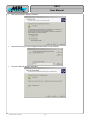
•
Click next and select “Specify a location”.
•
Select the directory you have unzipped the driver files to, then click OK.
•
Then the results will appear. Click Next.
2004 by MPL AG, Switzerland
19
MEH-10101-001 Rev. A
OSCI
User Manual
•
Windows ask you if you want to install the driver even though it is not signed. Click Yes.
•
Windows informs you that the installation has finished. Click Finish.
•
Then in the Device Manager a new device will appear. An MPL AG’s OSCI x-Port UART PCI Card with x
(4 or 8) Multifunction Devices.
2004 by MPL AG, Switzerland
20
MEH-10101-001 Rev. A
OSCI
User Manual
•
Then Windows will find a new Multifunction Device and you have to do the same procedure like for the
PCI Serial Port Device.
•
After the first Multifunction Device is proper installed the next Multifunction Devices will be installed
automatically. At the end of the procedure x (4 or 8) new OSCI Communications Port Devices will appear
in the Device Manager.
•
Don’t forget to configure all the new OSCI Communication Ports with the also installed OSCI
Configuration Tool in the Control Panel. For more information please refer to the chapter 7.3.2.
2004 by MPL AG, Switzerland
21
MEH-10101-001 Rev. A
OSCI
User Manual
7.3.1.3 WINDOWS XP
Windows XP searches a very long time for all the new hardware devices. As long as the symbol
is displayed in the right lower corner the installation is not finished and every manual change in the Device
Manager can damage the installation process. The following instructions guide you through the installation
process:
•
•
Install the OSCI hardware in your system (please refer to chapter 8 for more information).
At the next boot time Windows XP will find a new PCI Serial Port Device. Attend that Windows XP needs
a long time until the Hardware Wizard will appear. Select “Install from a list ...” then the installation
process goes faster. Click Next.
•
•
But first unzip the osciXPxx.zip file to the C:\TEMP directory or elsewhere on your system.
Select “Don’t search. I will choose ...”. Click Next.
2004 by MPL AG, Switzerland
22
MEH-10101-001 Rev. A
OSCI
User Manual
•
Select “Multi-port serial adapters”. Click Next.
•
Select “Have Disk ...”.
•
Select the directory you have unzipped the driver files to, then click OK.
2004 by MPL AG, Switzerland
23
MEH-10101-001 Rev. A
OSCI
User Manual
•
Windows will find an appropriate model for the OSCI hardware. Select the needed model and click Next.
•
Windows asks you about the Windows Logo Test. Click “Continue Anyway”.
•
Windows informs you that the installation has finished. Click Finish.
2004 by MPL AG, Switzerland
24
MEH-10101-001 Rev. A
OSCI
User Manual
•
•
•
Then Windows will find 4 or 8 new Multifunction Devices and you have to do for each Multifunction
Device the same procedure like for the PCI Serial Port Device.
If you do that correctly the Device Manager will display an “MPL AG’s OSCI x-Port UART PC/104-PLUS
Card” and x “OSCI Communications Port” devices. Dependent on the variant of your OSCI card x is 4 or
8:
Don’t forget to configure all the new OSCI Communication Ports with the also installed OSCI
Configuration Tool in the Control Panel. For more information please refer to the chapter 7.3.2.
2004 by MPL AG, Switzerland
25
MEH-10101-001 Rev. A
OSCI
User Manual
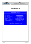
7.3.2 DRIVER CONFIGURATION
For the Windows driver settings there is a Control Panel Applet that you let configure the driver graphically.
For each OSCI serial port there is a page to set all the needed information.
NOTE:
It is important that you go through all the pages in the Control Panel
Applet and configures all the interface types you want. Else all OSCI
serial ports will stay disabled in hardware.
For more information about the several buttons and list boxes there is a help included in the OSCI Control
Panel Applet.
Figure 13: Control Panel Applet To Configure The OSCI Hardware
Don’t use the Windows specific Ports tool (in Windows NT only) out of the Control Panel for configuring the
OSCI hardware. It doesn’t support all the OSCI serial port features.
Attend that Terminal programs or other applications can change (with IoCtrls) standard settings like baud
rate, parity, flow control .. you have made with the OSCI Configuration Tool.
NOTE:
The OSCI ports COM numbering and the numbering in the Configuration Panel is in
WinXP and Win2000 systems from behind to ahead. Port 0 (first OSCI COM port in the
Windows system) is in WinXP and Win2000 systems the last hardware port.
2004 by MPL AG, Switzerland
26
MEH-10101-001 Rev. A
OSCI
User Manual
7.3.3 DRIVER IOCTRLS
7.3.3.1 IOCTRL DEFINITION
The windows drivers support all IoCtrls the standard Microsoft serial driver also supports. But there are also
some MPL AG specific IoCtrls you will find in the osciAPI.h file on the MPL AG homepage www.mpl.ch. The
File is also printed below. But for the latest version always have a look at the homepage.
With this special IoCtrls you can select which interface type you want, if RS232 or RS485/RS422 with full or
half duplex, and the RS485 auto direction control delay.
/*++
Module Name:
osciAPI.h
Copyright (c) 2004 MPL AG
Abstract:
This is the include file that defines all constants and types specific to the
serOSCI.sys driver from MPL AG. It can be used to make serOSCI driver specific
ioctrls from an application program.
All microsoft standard serial driver specific ioctrls are also included in the
serOSCI.sys driver and can be used by the application program.
Author:
Patrik Hossle (ph) 2004-03-18
Revision History:
2004-03-18
first edition
--*/
#ifndef _osciAPI_H_
#define _osciAPI_H_
//
// struct for IOCTL_OSCI_MPIO_READ_PLD / IOCTL_OSCI_MPIO_WRITE_PLD ioctrls
//
typedef struct _INTERFACE_MODE {
UCHAR RS232Enable;
// FALSE: rs232 disabled, TRUE: rs232 enabled
UCHAR RS485Enable;
// FALSE: rs485 disabled, TRUE: rs485 enabled
// -> in hardware the enable for rs232 is stronger than the enable for rs485
UCHAR FDEnable;
// FALSE: half duplex enable, TRUE: full duplex enable
} INTERFACE_MODE,*PINTERFACE_MODE;
//
// struct for IOCTL_OSCI_SET_RS485_DELAY / IOCTL_OSCI_GET_DELAY_DELAY ioctrls
//
typedef struct _RS485_DELAY {
UCHAR RS485Delay;
// delay in transmitter bit time. valid is 0 .. 15
// in auto rs485 half duplex mode the driver is disabled after
// this number in bit times (e.g. 9600 baud: bit time = 104.2 us)
} RS485_DELAY,*PRS485_DELAY;
//
// Define the various device type values. Note that values used by Microsoft
// Corporation are in the range 0-32767, and 32768-65535 are reserved for use
// by customers.
//
#define FILE_DEVICE_OSCI 0x00008005
//
// Macro definition for defining IOCTL and FSCTL function control codes. Note
// that function codes 0-2047 are reserved for Microsoft Corporation, and
// 2048-4095 are reserved for customers.
//
2004 by MPL AG, Switzerland
27
MEH-10101-001 Rev. A
OSCI
User Manual
#define OSCI_IOCTL_INDEX
0x805
// mpl ioctrls for handling the interface type
#define IOCTL_OSCI_MPIO_READ_PLD
CTL_CODE(FILE_DEVICE_OSCI,
METHOD_BUFFERED, FILE_ANY_ACCESS)
#define IOCTL_OSCI_MPIO_WRITE_PLD
CTL_CODE(FILE_DEVICE_OSCI,
METHOD_BUFFERED, FILE_ANY_ACCESS)
#define IOCTL_OSCI_SET_RS485_DELAY
CTL_CODE(FILE_DEVICE_OSCI,
METHOD_BUFFERED, FILE_ANY_ACCESS)
#define IOCTL_OSCI_GET_RS485_DELAY
CTL_CODE(FILE_DEVICE_OSCI,
METHOD_BUFFERED, FILE_ANY_ACCESS)
#endif
OSCI_IOCTL_INDEX+0x20,
OSCI_IOCTL_INDEX+0x21,
OSCI_IOCTL_INDEX+0x22,
OSCI_IOCTL_INDEX+0x23,
//_osciAPI_H_
7.3.3.2 IOCTRL EXAMPLE
Set COM10 to RS485 (with half duplex mode) and the RS485 auto direction control delay to 10 bit times.
#include “osciAPI.h”
...
... function(...){
unsigned long
CountReturned;
INTERFACE_MODE
InterfaceMode;
RS485_DELAY
RS485Delay;
...
hdriver = CreateFile(“\\\\.\\COM10”,
GENERIC_READ | GENERIC_WRITE,
0,
NULL,
OPEN_EXISTING,
0,
NULL);
InterfaceMode.RS232Enable = FALSE;
InterfaceMode.RS485Enable = TRUE;
InterfaceMode.FDEnable = FALSE;
DeviceIoControl(hdriver,
IOCTL_OSCI_MPIO_WRITE_PLD,
&InterfaceMode,
sizeof(INTERFACE_MODE),
NULL,
0,
(LPDWORD)&CountReturned,
0);
RS485Delay.RS485Delay = 10;
DeviceIoControl(hdriver,
IOCTL_OSCI_SET_RS485_DELAY,
&RS485Delay,
sizeof(RS485_DELAY),
NULL,
0,
(LPDWORD)&CountReturned,
0);
CloseHandle(hdriver);
...
}
7.4 TESTED OPERATING-SYSTEMS
The following combinations of operating systems and MPL single board computers with OSCIs are tested in
the lab:
PIP405: TBD
PIP5:
NT4.0
PIP6:
NT4.0
PIP7:
Linux with Kernel 2.6
PIP8:
Windows 2000, Windows XP SP1
2004 by MPL AG, Switzerland
28
MEH-10101-001 Rev. A
OSCI
User Manual
8. MOUNTING
The OSCI shall only be mounted by qualified personnel. MPL AG accepts no responsibility for any damage
to the host system or the OSCI module caused by the mounting procedure.
NOTE:
Before starting, verify that the host system is switched off and disconnected from the main power. Review
and observe the safety precautions description at the beginning of this manual to avoid personal injury or
damage to equipment.
8.1 PARTS NEEDED FOR MOUNTING
•
•
OSCI module
4 M3 x 6mm screws
8.2 MOUNTING DESCRIPTION
1. Turn the power on your host system off.
2. Plug the OSCI module to its place and insure that no pin is bent!
3. Insert and secure the screws at the mounting holes.
8.3 MECHANICAL DIMENSIONS
The location of the PC/104-Plus connectors and mounting holes you can find in the PC/104-Plus
Specification on the homepage of the PC/104 Consortium:
http://www.pc104.org/
The following picture is true for all OSCI variants. There are only little changes in the assembly between the
several variants.
2.54
1
2
O
N
22.2
20.3
2.54
95.9
90.2
Figure 14: OSCI Top View
2004 by MPL AG, Switzerland
29
MEH-10101-001 Rev. A
OSCI
User Manual
THIS PAGE IS INTENTIONALLY LEFT BLANK!
2004 by MPL AG, Switzerland
30
MEH-10101-001 Rev. A
OSCI
User Manual
THIS PAGE IS INTENTIONALLY LEFT BLANK!
2004 by MPL AG, Switzerland
31
MEH-10101-001 Rev. A
OSCI
User Manual
9. COPYRIGHT
Copyright © 2004 by MPL AG Elektronikunternehmen. All rights are reserved. Reproduction of this document
in part or whole, by any means is prohibited, without written permission from MPL AG
Elektronikunternehmen.
10. DISCLAIMER
MPL AG has fully tested the OSCI module and reviewed the documentation. However, MPL AG makes no
warranty or representation, either expressed, or implied, with respect to this product, its quality, performance,
merchantability, or fitness for a particular purpose.
In no event will MPL AG be liable for direct, indirect, special, incidental, or consequential damages resulting
from any defect in the product or its documentation, even if advised of the possibility of such damages. In
particular MPL AG shall have no liability for any parts connected to this product.
MPL AG reserves the right to make changes to any product herein to improve reliability, function or design.
11. SUPPORT
In case of questions please feel free to contact us at our homepage (www.mpl.ch) or per email
([email protected]).
Our local Distributor:
2004 by MPL AG, Switzerland
32
MEH-10101-001 Rev. A