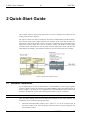
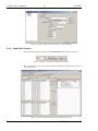
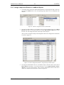
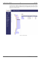
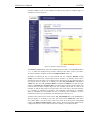
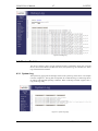
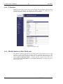
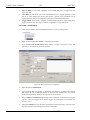
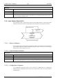
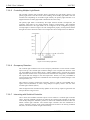
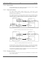
1
L-DALI DALI Light Controller User’s Manual LOYTEC electronics GmbH Contact LOYTEC Blumengasse 35 A-1170 Vienna AUSTRIA/EUROPE [email protected] http://www.loytec.com Version 2.0.1 Document 88077105 LOYTEC MAKES AND YOU RECEIVE NO WARRANTIES OR CONDITIONS, EXPRESS, IMPLIED, STATUTORY OR IN ANY COMMUNICATION WITH YOU, AND LOYTEC SPECIFICALLY DISCLAIMS ANY IMPLIED WARRANTY OF MERCHANTABILITY OR FITNESS FOR A PARTICULAR PURPOSE. THIS PRODUCT IS NOT DESIGNED OR INTENDED FOR USE IN EQUIPMENT INTENDED FOR SURGICAL IMPLANT INTO THE BODY OR OTHER APPLICATIONS INTENDED TO SUPPORT OR SUSTAIN LIFE, FOR USE IN FLIGHT CONTROL OR ENGINE CONTROL EQUIPMENT WITHIN AN AIRCRAFT, OR FOR ANY OTHER APPLICATION IN WHICH IN THE FAILURE OF SUCH PRODUCT COULD CREATE A SITUATION IN WHICH PERSONAL INJURY OR DEATH MAY OCCUR. LOYTEC MAKES NO REPRESENTATION AND OFFERS NO WARRANTY OF ANY KIND REGARDING OF ANY THIRDPARTY COMPONENTS MENTIONED IN THIS MANUAL. No part of this publication may be reproduced, stored in a retrieval system, or transmitted, in any form or by any means, electronic, mechanical, photocopying, recording, or otherwise, without the prior written permission of LOYTEC. LC3020, L-Chip, L-Core, L-DALI, L-GATE, L-INX, L-IOB, L-IP, LPA, L-Proxy, L-Switch, L-Term, L-VIS, L-WEB, and ORION™ stack are trademarks of LOYTEC electronics GmbH. LonTalk®, LONWORKS®, Neuron®, LONMARK®, LonMaker®, i.LON®, and LNS® are trademarks of Echelon Corporation registered in the United States and other countries. L-DALI User’s Manual 3 LOYTEC Contents 1 Introduction ................................................................................................ 11 1.1 Overview ............................................................................................................ 11 1.2 L-DALI Models ................................................................................................. 15 1.3 Scope................................................................................................................... 15 2 Quick-Start Guide ...................................................................................... 16 2.1 Hardware Installation ....................................................................................... 16 2.2 Configuration of IP Address ............................................................................ 17 2.2.1 IP Configuration via Console ................................................................... 17 2.2.2 IP Configuration via the Web Interface .................................................... 18 2.3 Configuration with PC Software (LDALI-3E10X only) ................................ 20 2.3.1 Connect to Device in Stand-Alone Mode................................................. 21 2.3.2 Scan DALI Channel ................................................................................. 22 2.3.3 Assign Lamps and Sensor to LONMARK Objects ..................................... 23 2.3.4 Grouping Lamps....................................................................................... 24 2.3.5 Calibrate Light Sensor.............................................................................. 24 2.3.6 Parameterize the Constant Light Controller ............................................. 26 2.3.7 Download Configuration .......................................................................... 26 2.4 Configuration using Web Interface ................................................................. 28 2.4.1 Scan DALI Channel ................................................................................. 28 2.4.2 Assign Lamps and Sensor to LONMARK/BACnet Objects ....................... 29 2.4.3 Grouping Lamps....................................................................................... 30 2.4.4 Calibrate Light Sensor.............................................................................. 31 2.4.5 Parameterize the Constant Light Controller ............................................. 31 2.5 Configuration with CEA-709 Network Management Tool (LDALI-3E10X only) .................................................................................................................... 32 2.6 Configuration of BACnet Interface (LDALI-ME20X only) .......................... 33 2.6.1 Configure BACnet Interface .................................................................... 33 2.6.2 Set up Constant Light Controller ............................................................. 33 3 Hardware Installation ............................................................................... 35 3.1 Enclosure............................................................................................................ 35 3.1.1 L-DALI..................................................................................................... 35 3.2 Product Label .................................................................................................... 35 3.3 Mounting ............................................................................................................ 36 3.4 LED signals ........................................................................................................ 36 3.4.1 Power LED ............................................................................................... 36 3.4.2 Status LED ............................................................................................... 36 Version 2.0.1 LOYTEC electronics GmbH L-DALI User’s Manual 4 LOYTEC 3.4.3 FT Activity LED (LDALI-3E10X only) .................................................. 36 3.4.4 MSTP Activity LED (LDALI-ME20X only) ........................................... 36 3.4.5 Ethernet Link LED .................................................................................. 37 3.4.6 Ethernet Activity LED ............................................................................. 37 3.4.7 Ethernet Config LED ............................................................................... 37 3.4.8 CN/IP LED .............................................................................................. 37 3.4.9 DALI Activity LEDs ................................................................................ 38 3.4.10 Wink Action (LDALI-3E10X only) ......................................................... 38 3.5 Buttons ............................................................................................................... 38 3.5.1 Status Button ........................................................................................... 38 3.5.2 DALI Mode Button.................................................................................. 38 3.5.3 DALI Channel Button.............................................................................. 39 3.5.4 DALI Program Button ............................................................................. 39 3.6 DIP Switch Settings .......................................................................................... 39 3.7 Terminal Layout and Power Supply ............................................................... 40 3.8 Wiring ................................................................................................................ 41 3.8.1 LDALI-ME20X ....................................................................................... 41 3.8.2 LDALI-3E10X ......................................................................................... 41 4 Web Interface ............................................................................................. 42 4.1 Device Information and Account Management .............................................. 42 4.2 Device Configuration ........................................................................................ 44 4.2.1 System Configuration .............................................................................. 44 4.2.2 Backup and Restore ................................................................................. 45 4.2.3 Port Configuration ................................................................................... 46 4.2.4 IP Configuration ...................................................................................... 47 4.2.5 CEA-709 Configuration (LDALI-3E10X only) ....................................... 48 4.2.6 CEA-852 Device Configuration (LDALI-3E10X only) ........................... 48 4.2.7 BACnet Configuration (LDALI-ME20X only)........................................ 50 4.2.8 BACnet/IP Configuration (LDALI-ME20X only) ................................... 50 4.2.9 MS/TP Configuration (LDALI-ME20X only) ......................................... 51 4.2.10 E-Mail Configuration .............................................................................. 52 4.2.11 DALI Installation ..................................................................................... 53 4.2.12 DALI Groups ........................................................................................... 59 4.2.13 Data Points .............................................................................................. 59 4.2.14 Trend ....................................................................................................... 62 4.2.15 Scheduler ................................................................................................. 62 4.2.16 Calendar .................................................................................................. 64 4.2.17 Alarm ....................................................................................................... 65 4.2.18 Debug ...................................................................................................... 66 Version 2.0.1 LOYTEC electronics GmbH L-DALI User’s Manual 4.3 5 LOYTEC Device Statistics ................................................................................................. 67 4.3.1 System Log............................................................................................... 67 4.3.2 IP Statistics .............................................................................................. 68 4.3.3 CEA-852 Statistics (LDALI-3E10X only) ............................................... 68 4.3.4 Enhanced Communications Test (LDALI-3E10X only) .......................... 69 4.3.5 CEA-709 Statistics (LDALI-3E10X only) ............................................... 70 4.3.6 BACnet MS/TP Statistics (LDALI-ME20X only).................................... 71 4.3.7 DALI Statistics ......................................................................................... 72 4.3.8 Scheduler Statistics Page ......................................................................... 73 4.3.9 Alarm Log Page........................................................................................ 73 4.4 Reset, Contact, Logout ...................................................................................... 74 5 Concepts ...................................................................................................... 75 5.1 Alarming ............................................................................................................ 75 5.2 Historical Alarm Log ........................................................................................ 75 5.3 Scheduling .......................................................................................................... 76 5.4 Trending ............................................................................................................. 78 5.5 E-Mail................................................................................................................. 79 6 The L-DALI Configurator (LDALI-3E10X only)................................... 80 6.1 Installation ......................................................................................................... 80 6.1.1 Software Installation ................................................................................ 80 6.1.2 Registration as a Plug-In .......................................................................... 81 6.1.3 Operating Modes ...................................................................................... 83 6.2 Workflows for the L-DALI ............................................................................... 83 6.2.1 Involved Configuration Files.................................................................... 83 6.2.2 On-Line .................................................................................................... 83 6.2.3 Off-Line ................................................................................................... 84 6.2.4 Replace an L-DALI .................................................................................. 85 6.2.5 Using non-standard network interface ..................................................... 86 6.3 Adding L-DALI ................................................................................................. 86 6.4 Replace an L-DALI ........................................................................................... 89 6.5 Working with Configuration Properties ......................................................... 92 6.6 Enable Legacy NM Mode ................................................................................. 94 6.7 Using the L-DALI Configurator ...................................................................... 94 6.7.1 Starting as an LNS Plug-In ....................................................................... 94 6.7.2 Starting Stand-Alone ................................................................................ 94 6.7.3 Uploading the Configuration ................................................................... 95 6.7.4 Configuration Download .......................................................................... 96 6.7.5 Upload the System Log ............................................................................ 99 6.7.6 Backup and Restore ............................................................................... 100 Version 2.0.1 LOYTEC electronics GmbH L-DALI User’s Manual 6.8 6 LOYTEC DALI Installation ............................................................................................ 100 6.8.1 DALI Installation Tab ............................................................................ 100 6.8.2 DALI Groups Tab .................................................................................. 103 6.8.3 DALI Channels Tab ............................................................................... 104 6.9 Parameter Configuration ............................................................................... 104 6.9.1 Reset Run Hours and Energy Count ...................................................... 105 6.9.2 Calibrate Light Sensor ........................................................................... 106 6.9.3 Calibrate Constant Light Controller ...................................................... 106 6.9.4 Modify Sunblind Controller Event Priorities ......................................... 107 6.9.5 Link Sunblind Controller to Constant Light Controller ......................... 108 6.9.6 Configure Emergency Light Auto-Test Calendar .................................. 108 6.10 Data Point Manager ....................................................................................... 109 6.10.1 Folder List ............................................................................................. 109 6.10.2 Network Port Folders ............................................................................. 110 6.10.3 Data Point List ....................................................................................... 110 6.10.4 Property View ........................................................................................ 111 6.10.5 User Registers ........................................................................................ 112 6.11 E-Mail Templates............................................................................................ 113 6.11.1 Create an E-Mail Template .................................................................... 113 6.11.2 Trigger E-Mails ..................................................................................... 114 6.11.3 Attachments ........................................................................................... 115 6.11.4 Limit E-Mail Send Rate......................................................................... 116 6.12 Local Schedule and Calendar ........................................................................ 116 6.12.1 Create a local Calendar .......................................................................... 116 6.12.2 Create Calendar Pattern ......................................................................... 117 6.12.3 Create a Local Scheduler ....................................................................... 117 6.12.4 Configure Scheduled Data Points .......................................................... 118 6.12.5 Configure Daily Schedules .................................................................... 119 6.12.6 Configure Exception Days ..................................................................... 121 6.12.7 Configure Embedded Exceptions .......................................................... 122 6.12.8 Configure Control Data Points .............................................................. 122 6.12.9 Using the Local Scheduler ..................................................................... 123 6.12.10 6.13 Limitations for Local CEA-709 Schedulers...................................... 123 Local Alarming ............................................................................................... 123 6.13.1 Create an Alarm Condition .................................................................... 123 6.13.2 Deliver Alarms via E-Mail..................................................................... 126 6.13.3 Create an Alarm Log.............................................................................. 126 6.13.4 Limitations for CEA-709 Alarm Servers ............................................... 127 6.14 Version 2.0.1 Local Trending................................................................................................ 127 LOYTEC electronics GmbH L-DALI User’s Manual 7 LOYTEC 6.14.1 Create a Local Trend .............................................................................. 127 6.14.2 Configure Trended Data Points .............................................................. 129 6.14.3 Trend Triggers ........................................................................................ 130 6.14.4 Download Trend Data in CSV Format ................................................... 130 6.14.5 Deliver Trend Data via E-Mail ............................................................... 131 6.14.6 Limitations for Local CEA-709 Trends.................................................. 131 6.15 Math Objects ................................................................................................... 132 6.15.1 Create a Math Object ............................................................................. 132 6.15.2 Editing a Math Object ............................................................................ 133 6.16 Project Settings ................................................................................................ 133 6.16.1 General ................................................................................................... 134 6.16.2 CEA-709 Settings .................................................................................. 134 6.16.3 CEA-709 AST Settings .......................................................................... 135 6.16.4 System Settings ...................................................................................... 136 7 Operating Interfaces ................................................................................ 138 7.1 Common Interface ........................................................................................... 138 7.1.1 Schedule and Calendar XML Files ......................................................... 138 7.1.2 Trend Log CSV File ............................................................................... 138 7.1.3 Alarm Log CSV File .............................................................................. 140 7.1.4 Emergency Light Test Log CSV File ..................................................... 140 7.2 CEA-709 Interface (LDALI-3E10X only) ..................................................... 140 7.2.1 Node Object #0000 ................................................................................ 141 7.2.2 Real-Time Keeper Object #3300 ............................................................ 141 7.2.3 Calendar Object #0006 .......................................................................... 141 7.2.4 Scheduler Object #0007 ......................................................................... 141 7.2.5 Lamp actuator Object #3040 .................................................................. 142 7.2.6 Light Sensor Object #1010 .................................................................... 162 7.2.7 Occupancy Sensor Object #1060 ........................................................... 164 7.2.8 Constant Light Controller Object #3050 ................................................ 166 7.2.9 Sunblind Controller Object #6111 ......................................................... 180 7.2.10 Globals #0005 ........................................................................................ 199 7.3 BACnet Interface (LDALI-ME20X only) ...................................................... 206 7.3.1 Interface Version .................................................................................... 207 7.3.2 Device Object......................................................................................... 207 7.3.3 Light Output Objects.............................................................................. 213 7.3.4 Sensor Objects ....................................................................................... 232 7.3.5 Constant Light Controller ...................................................................... 235 7.3.6 Alarming, Scheduling and Trending Objects (AST) .............................. 242 7.3.7 Client Mapping CSV File ...................................................................... 242 Version 2.0.1 LOYTEC electronics GmbH L-DALI User’s Manual 8 LOYTEC 7.3.8 EDE Export of BACnet Objects ............................................................ 243 7.4 DALI Interface ................................................................................................ 243 7.4.1 Multi-Master Operation ......................................................................... 243 7.4.2 DALI Device Types ............................................................................... 244 7.4.3 DALI Channel Bridging ........................................................................ 245 7.4.4 Special Use Cases .................................................................................. 245 8 Network Media ......................................................................................... 246 8.1 FT (LDALI-3E10X only) ................................................................................ 246 8.2 MS/TP (LDALI-ME20X only) ....................................................................... 247 9 L-DALI Firmware Update ...................................................................... 248 9.1 Firmware Update via the L-DALI Configurator (LDALI-3E10X only) .... 248 9.2 Firmware Update via FTP ............................................................................. 250 9.3 Firmware Update via the Console ................................................................. 250 10 Troubleshooting ....................................................................................... 253 10.1 Technical Support........................................................................................... 253 10.2 Statistics on the Console ................................................................................. 253 10.2.1 Connecting to the Console..................................................................... 253 10.2.2 Reset configuration (load factory defaults) ............................................ 254 10.2.3 Device Statistics Menu .......................................................................... 254 10.3 DALI Protocol Analyzer ................................................................................ 256 10.3.1 Starting DALI PA via Console .............................................................. 256 10.3.2 Starting DALI PA via Telnet ................................................................. 256 10.3.3 DALI PA Information ............................................................................ 257 11 Specifications ............................................................................................ 258 11.1 L-DALI ............................................................................................................ 258 11.1.1 Physical Specifications .......................................................................... 258 11.1.2 Resource Limits (LDALI-3E10X) ......................................................... 258 12 Revision History ....................................................................................... 259 Version 2.0.1 LOYTEC electronics GmbH L-DALI User’s Manual 9 LOYTEC Abbreviations 100BaseT ............................ 100 Mbps Ethernet network with RJ-45 plug Aggregation ......................... Collection of several CEA-709 packets into a single CEA-852 packet AST ..................................... Alarming, Scheduling, Trending BACnet ............................... Building Automation and Control Network CC ....................................... Configuration Client, also known as CN/IP Device CEA-709 ............................. Protocol standard for LONWORKS networks CEA-852 ............................. Protocol standard for tunneling CEA-709 packets over IP channels CN ....................................... Control Network CN/IP .................................. Control Network over IP CN/IP Channel .................... logical IP channels that tunnels CEA-709 packets according CEA-852 CN/IP packet ....................... IP packet that tunnels one or multiple CEA-709 packet(s) COV .................................... change-of-value CR ....................................... Channel Routing CS........................................ Configuration Server that manages CEA-852 IP devices DA ....................................... Data Access DALI ................................... Digital Addressable Lighting Interface, see IEC 62386 DHCP .................................. Dynamic Host Configuration Protocol, RFC 2131, RFC 2132 DL ....................................... Data Logger, Datenlogger (Webservice) DNS..................................... Domain Name Server, RFC 1034 DST ..................................... Daylight Saving Time GMT .................................... Greenwich Mean Time IP ......................................... Internet Protocol LSD Tool ............................. LOYTEC System Diagnostics Tool IP-852 .................................. Logical IP-Channel, for tunneling CEA-709 packets according to CEA-852 LSD Tool ............................. LOYTEC System Diagnostics Tool MAC ................................... Media Access Control MD5 .................................... Message Digest 5, a secure hash function, see Internet RFC 1321 MS/TP ................................. Master/Slave Token Passing (this is a BACnet data link layer) NAT .................................... Network Address Translation, see Internet RFC 1631 NV ....................................... Network Variable OPC ..................................... Open Process Control RNI...................................... Remote Network Interface RTT ..................................... Round-Trip Time RTU..................................... Remote Terminal Unit SL ........................................ Send List SMTP .................................. Simple Mail Transfer Protocol SNTP ................................... Simple Network Time Protocol SNVT .................................. Standard Network Variable Type Version 2.0.1 LOYTEC electronics GmbH L-DALI User’s Manual 10 LOYTEC SSL ..................................... Secure Socket Layer TLS ..................................... Transport Layer Security UI ........................................ User Interface UNVT ................................. User-Defined Network Variable Type UTC .................................... Universal Time Coordinated XML ................................... eXtensible Markup Language Version 2.0.1 LOYTEC electronics GmbH L-DALI User’s Manual 11 LOYTEC 1 Introduction 1.1 Overview The L-DALI controllers for LONMARK (LDALI-3E10X) and BACnet (LDALI-ME20X) are DALI gateways with built-in light controller functionality. systems DALI (Digital Addressable Lighting Interface) is defined in the international standard IEC 60929 Annex E and the newer IEC 62386. It is used to dim and switch luminaries from most leading manufacturers. DALI also supports devices like multi-sensors (e.g. for brightness, occupancy, etc.) and intelligent switches. Figure 1: L-DALI supports up to four DALI channels Version 2.0.1 LOYTEC electronics GmbH L-DALI User’s Manual 12 LOYTEC The L-DALI lineup features 1, 2, or 4 independent DALI channels. Up to 64 DALI-based luminaries per DALI channel can be controlled individually or via 16 groups. All luminaries are monitored for lamp defect. L-DALI can provide this information to the Building Management System (BMS) through its NV or BACnet interface respectively. For CEA-709 communication IP-852 (Ethernet/IP) and TP/FT-10 are supported, for BACnet communication BACnet/IP and BACnet MS/TP are supported. LDALI-3E101, LDALI-3E102, and LDALI-3E104 are gateways connecting a DALI network to a CEA-709 network, LDALI-ME204 is a gateway connecting a DALI network to a BACnet network. On the DALI network the L-DALI controller represents a DALI master controller. On the CEA-709 or BACnet network the L-DALI controller offers a NV interface or a BACnet server objects respectively to control the ballasts and the sensors connected for the DALI network. The constant light controller (LONMARK functional profile #3050, BACnet Loop object) allows controlling DALI ballasts with lighting nodes on the CEA-709 or BACnet network. On the LDALI-3E10X (LONMARK) version a built-in sunblind controller (LONMARK functional profile #6111) interacts with other nodes on the CEA-709 network. Interaction between the sunblind and constant light controller applications allows adjusting sunblinds depending on the constant light controller output, e.g. for energy saving concepts. L-DALI supports automation functions such as alarming, scheduling, and trending. The L-DALI controllers offer local scheduling services including the possibility to configure several local and remote 24 hour schedulers through the Web UI. Alarming includes the functionality to generate, deliver, acknowledge, and display alarm conditions and logs regardless whether the condition comes from the DALI or the CEA-709/BACnet network. The trending capability includes periodic and event triggered data logging of values and time stamps. Alarms and trend data are stored on the device accessible via an FTP connection as CSV files. Figure 2: Using L-DALI together with the L-WEB product family L-DALI devices can be integrated with LWEB-801 Server using OPC XML-DA to save trend and log files for long term storage. In addition, the optional LWEB-820 Master Schedule Configurator gives the ability for remotely managing schedulers and calendars. LWEB-830 Dream Report is used to analyze data and generate reports. L-DALI supports Version 2.0.1 LOYTEC electronics GmbH L-DALI User’s Manual 13 LOYTEC event-driven E-Mail notification as a result of a predefined action triggered by a specific status or an exceeded high limit. E-Mail notification can also be used to forward trend and log files to central SQL databases for long term storage (see LWEB-801 for details). L-DALI supports common mathematical operations and functions, as well as Boolean expressions. Some lighting controller applications do not need a connection to the CEA-709 or BACnet network. Therefore the L-DALI controller can control a DALI network as a standalone device with the aid of the supported automation functions (alarming, scheduling, and trending). Connected to an IP network, remote access allows to set parameters and to read the system status. The complete configuration can be done through the built-in Web server. The commissioning and maintenance of the DALI system can be done using a standard Web browser on a PC. The configuration can also be done via a PC based configuration software (LDALI-3E10X only). The L-DALI offers the following features: Version 2.0.1 DALI gateway and controller Supports 1, 2, or 4 DALI channels (dependent on model) Direct control of up to 64 DALI devices per DALI channel Direct control of up to 16 DALI groups per DALI channel Scene control for up to 16 groups and one broadcast scene per DALI channel Detect lamp and ballast failure on DALI luminaries and signals Simple replacement of (broken) DALI devices (no configuration tool required) DALI Multi-Master capable Built-in DALI protocol analyzer Supports Alarming, Scheduling, and Trending (AST™) Supports common mathematical operations and functions as well as Boolean expressions Supports event-driven E-Mail notification Supports periodic testing of emergency lights Supports lamp burn-in mode Support calculation of energy consumption and run-hours Configuration via Web interface Firmware update via serial, CEA-709, or Ethernet port Operating Voltage: 12-35 V DC or 12-24 V AC 157 x 86 x 60 (L x B x H in mm) or 9 TE LOYTEC electronics GmbH L-DALI User’s Manual 14 LOYTEC DIN rail mountable LDALI-3E10X (LONMARK, CEA-709) only: Fully compliant with CEA-709, CEA-852, and EN 14908 standard Supports LONMARK TP/FT-10 or CEA-852 Ethernet (IP-852) channels (selectable) Control of DALI capable ballasts via NVs Retrieve information from DALI capable sensors via NVs Supports LONMARK Functional Profiles: o Lamp Actuator #3040 o Light Sensor #1010 o Occupancy Sensor #1060 o Constant Light Controller #3050 o Sunblind Controller #6111 o Scheduler #0007 o Calendar #0006 LDALI-ME20X (BACnet) only: Version 2.0.1 Fully compliant with BACnet standard ANSI/ASHRAE 135-2008 Supports BACnet/IP or BACnet MS/TP (selectable) Control of DALI capable ballasts and sensors via BACnet server objects Retrieve information from DALI capable sensors via BACnet server objects BACnet client functionality (configurable) Supports the following BACnet server objects: o Analog Output objects to control DALI ballasts, groups, and channels o Multi-State Output objects for scene control of DALI groups and channels o Analog Input objects providing feedback from DALI ballast, groups, and channels o Analog Input objects providing status information from DALI groups and channels o Accumulator objects providing estimated energy usage of DALI groups and channels LOYTEC electronics GmbH L-DALI User’s Manual 15 LOYTEC o Analog Input object providing lux level information from supported DALI sensors o Binary Input objects providing occupancy information from supported DALI sensors o Loop objects providing constant light controller functionality 1.2 L-DALI Models This Section provides an overview of the different L-DALI models in Table 1. This table identifies the different features of the L-DALI models. Models that possess a certain feature have a check mark () in the respective column. If a feature is not available in the particular model, the column is left blank. ME204 1 2 4 4 CEA-709 (FT) CEA-852 (IP) 3E102 DALI channels Features 3E101 3E104 L-DALI Model BACnet MS/TP BACnet IP LDALI Configurator Table 1: Available features in different L-DALI models 1.3 Scope This document covers , LDALI-3E10X devices with firmware version 2.1, LDALI-ME204 devices with firmware version 2.2, and the L-DALI Configuration Software version 1.1. Version 2.0.1 LOYTEC electronics GmbH L-DALI User’s Manual 16 LOYTEC 2 Quick-Start Guide This Chapter contains step-by-step instructions on how to configure the L-DALI for the simple project shown in Figure 3. The project consists of a single room (Room 306) which is illuminated by four DALI lamps. Two of those lamps form a light band near the windows of the room and the other two lamps form a light band near the corridor. The room is equipped with a DALI multi-sensor which acts as both a light sensor and an occupancy sensor. The build-in constant light controller of the L-DALI device uses the input from the DALI multi-sensor and dims the DALI ballasts accordingly. The sunblind controller is not used in this quick-start example. Figure 3: Quick-Start Example Project 2.1 Hardware Installation It is recommended to use the LDALI-PWR4-U or LDALI-PWR2-U power supply together with the L-DALI. Connect the L-DALI to the LDALI-PWR4-U and to the DALI network as shown in Figure 4. To allow for easy configuration it is recommended to always connect the L-DALI to the Ethernet network. More detailed instructions are given in Chapter 3. Important: Do not connect terminal 26 to earth ground! After the DALI ballasts have been installed and connected to the DALI network, the installation can be tested by following these steps: 1. Version 2.0.1 Check that the DALI LEDs (“DALI x ACT”, where x is 1 to 4) do not light up red. If one of these LEDs is red, check the proper connection of the bus power supply for the corresponding channel. LOYTEC electronics GmbH L-DALI User’s Manual 17 LOYTEC 2. Press the DALI mode button (“ON/OFF/AUTO”) on the front panel of the L-DALI once. Now all DALI ballasts should be switched on (maximum level) and the DALI LEDs on the L-DALI should light up green. 3. Press the DALI mode button again. Now all DALI ballasts should be switched off and the DALI LEDs on the L-DALI should light up orange. 4. Press the DALI mode button again. This should not change the state of the DALI ballasts but return the L-DALI to the auto-mode (control via CEA-709/BACnet interface). Figure 4: Basic Hardware Installation. 2.2 Configuration of IP Address The L-DALI can be configured via a console interface or via the Web interface. To configure the L-DALI, the following steps have to be performed: Note: 1. Setup IP configuration (see Sections 2.2.1 and 2.2.2). 2. Setup the DALI network (see Section 2.3). This setup procedure assumes the use of the IP interface. 2.2.1 IP Configuration via Console Use a PC terminal program with the communication settings set to 38,400 bps / 8 data bits / no parity / 1 stop bit / no handshake. To connect COM1 of the PC to the Console on the Version 2.0.1 LOYTEC electronics GmbH L-DALI User’s Manual 18 LOYTEC device, use a standard null-modem cable with full handshaking. Power up the device or press Return if the device is already running. The following menu should appear on the terminal: Device Main Menu [1] [2] [3] [4] [5] [6] [7] [8] [9] Show device information Serial firmware upgrade System configuration DALI maintenance IP configuration CEA-852 device configuration CEA-709 configuration Reset configuration (factory defaults) Device statistics [a] Data Points [0] Reset device Please choose: Figure 5: Device Main Menu Select ‘5’ from the device main menu and enter the IP address, netmask, and gateway address. Note that you must use different IP addresses if you are using multiple IP devices in your setup. IP Configuration Menu [1] [2] [3] [4] [5] [6] [7] [9] [0] [b] DHCP : disabled IP Address : 192.168.1.254 IP Netmask : 255.255.255.0 IP Gateway : 192.168.1.1 Hostname : new Domainname : <unset> DNS Servers : <unset> MAC Address : 00:0A:B0:01:0C:9F (factory default) NTP Servers : <unset> (out-of-sync) Link Speed & Duplex : Auto Detect [q] Quit without saving [x] Exit and save Please choose: Figure 6: Enter basic IP settings. Press ‘x’ to save the IP settings and reset the device with the main menu item ‘0’ in order to let the new IP settings take effect. Important! The default IP address 192.168.1.254 is only set for configuration access. It must be changed in order to make the device functional. 2.2.2 IP Configuration via the Web Interface As an alternative to the console interface the Web interface can be used to configure the device. In a Web browser enter the default IP address 192.168.1.254 of the L-DALI. Note that if your PC has an IP address in a subnet other than 192.168.1.xxx please open a command tool and enter the following route command to add a route to the L-DALI. To Add a Route to the Device Version 2.0.1 1. Windows START Run 2. Enter ‘cmd’ and click OK. 3. In the command window enter the command line LOYTEC electronics GmbH L-DALI User’s Manual 19 LOYTEC route add 192.168.1.254 %COMPUTERNAME% In Windows7 replace %COMPUTERNAME% with the PC’s actual IP address. 4. Then open your Web browser and type in the default IP address 192.168.1.254. Figure 7: Example Start Screen 5. Click on Config in the left menu. You will be asked to enter the administrator password in order to change the IP settings. Enter ‘loytec4u’ and select Login. Figure 8: Enter ‘loytec4u’ as the default administrator password. Version 2.0.1 LOYTEC electronics GmbH L-DALI User’s Manual 20 LOYTEC 6. The Config menu opens. Click on Port Config in the Config menu and select Ethernet tab. Enter the IP address, the IP netmask, and IP gateway for this device as shown in Figure 9. 7. Press Save Settings and then reset the device by selecting Reset in the highlighted text. This changes the IP settings of the device. Figure 9: Enter IP address and gateway. 2.3 Configuration with PC Software (LDALI-3E10X only) For the LDALI-3E10X family (CEA-709/LONMARK) a PC based configuration software – the LDALI Configurator – is available. For the LDALI-ME20X family (BACnet) the web interface can be used for configuration (see Section 2.4). Install the L-DALI configuration software from the setup.exe. This file can be downloaded from www.loytec.com. This tool can be used as a stand-alone tool or as LNS plug-in. To show that the DALI installation can be done without an LNS database, we will use the L-DALI configuration software as a stand-alone tool in this quick-start example. A detailed description of the L-DALI configuration software can be found in Chapter 6. Version 2.0.1 LOYTEC electronics GmbH L-DALI User’s Manual 21 LOYTEC Figure 10: L-DALI Configuration Software, Start 2.3.1 Connect to Device in Stand-Alone Mode 1. Select the FTP connection method by clicking on the FTP connect button in the tool bar as shown in Figure 11. Figure 11: L-DALI Configuration Software, FTP Connect Version 2.0.1 2. In the FTP connection dialog (see Figure 12) enter the IP address of the L-DALI, the user name and password. The default user is ‘admin’ and the default password is ‘loytec4u’ (older firmware versions used ‘admin’). 3. Optionally, click on New and enter a user-defined name for this connection. That name can be selected later to connect. Click on Save to store that connection. 4. If your device is located behind a NAT router or firewall, you may change the FTP, Telnet, and HTTP ports to your needs for accessing the device. Clicking Save also stored these settings. 5. Click on Connect. This establishes the connection to the device. 6. The L-DALI configuration software asks if you want to upload the current configuration of the device. You can cancel this dialog because in this quick-start we configure the device from scratch. LOYTEC electronics GmbH L-DALI User’s Manual 22 LOYTEC Figure 12: L-DALI Configuration Software, FTP Connection Dialog 2.3.2 Scan DALI Channel 1. Select the DALI channel and click on the Scan Channel button shown in Figure 13. Figure 13: L-DALI Configuration Software, Scan Channel 2. The L-DALI device scans the selected channel and displays all detected devices as shown in Figure 14. Figure 14: L-DALI Configuration Software, Detected DALI Devices Version 2.0.1 LOYTEC electronics GmbH L-DALI User’s Manual 23 LOYTEC 2.3.3 Assign Lamps and Sensor to LONMARK Objects 1. To identity which of the four detected DALI ballasts is which physical lamp, select one and click the Wink button. The corresponding lamp blinks for the configured wink duration. Figure 15: L-DALI Configuration Software, Wink Button 2. To assign an DALI ballast to a LONMARK object, select the ballast in the list of DALI Devices and drag it to the desired position in the Lamp Actuator objects list on the left side. You can change the names of the lamp actuator objects. After you have assigned all lamps and changed the names the configuration should look as shown in Figure 16. Figure 16: L-DALI Configuration Software, Assigned Lamp Actuator Objects 3. Version 2.0.1 To assign the DALI multi-sensor to a LONMARK object, select the sensor in the list of DALI Devices and drag it to the desired position in the Light/Occupancy Sensor objects list on the lower left side. After you have changed the names of the sensor object the configuration should look as shown in Figure 17. LOYTEC electronics GmbH L-DALI User’s Manual 24 LOYTEC Figure 17: L-DALI Configuration Software, Assigned Light/Occupancy Sensor Object 2.3.4 Grouping Lamps Lamps which are assigned to a group can be controlled together by the corresponding LONMARK group object. We will create two groups: One for the lamps near the window and one for the lamps near the corridor. 1. In the L-DALI configuration software switch to the DALI Groups tab. 2. Add the two lamps near the window to group 0 and the two lamps near the corridor to group 1. Assign names to the groups as shown in Figure 18. Figure 18: L-DALI Configuration Software, Group Configuration 2.3.5 Calibrate Light Sensor The L-DALI device allows calibrating the light sensor under up to seven different light conditions to counter any non-linearity of the sensor. However, in many cases it is enough to calibrate the sensor with a single light condition which is near the setpoint. In this quickstart only one lux measurement is performed. 1. Version 2.0.1 In the L-DALI configuration software switch to the Parameters tab. LOYTEC electronics GmbH L-DALI User’s Manual 2. 25 LOYTEC Select the light sensor index 0 and click on the Calibrate Light Sensor… button as shown in Figure 19. The light sensor calibration window as shown in Figure 20 in displayed. Figure 19: Parameterize Light Sensor 3. Measure the current lux level at the reference area (e.g. desk) using a luxmeter. 4. Enter the measured lux level in the input field and select the index 0. 5. Press the Calibrate button. 6. Close the dialog by pressing the Done button. Figure 20: Calibrate Light Sensor Version 2.0.1 LOYTEC electronics GmbH L-DALI User’s Manual 26 LOYTEC 2.3.6 Parameterize the Constant Light Controller 1. In the L-DALI configuration software switch to the Parameters tab. 2. Select the constant light controller with index 0 as shown in Figure 21. The parameters of the selected constant light controller are displayed in the lower half of the window. 3. Change the parameter nciClMode to CL_MODE_REGULATOR. This parameter selects the operating mode. The REGULATOR mode is used if a light/occupancy sensor is installed which measures the indoor illumination. 4. Change the setpoint of the constant light controller (nciLuxSetpoint) to 700. 5. You can leave the default values for the remaining parameters. For a description of the constant light controller functionality and the parameters refer to Section 7.2.8. Figure 21: Parameterize Constant Light Controller 2.3.7 Download Configuration 1. Version 2.0.1 To download the configuration into the L-DALI device click on the Download Configuration button in the toolbar. LOYTEC electronics GmbH L-DALI User’s Manual 27 LOYTEC Figure 22: L-DALI Configuration Software, Download Configuration 2. Because we have changed only the DALI configuration and the parameters it is sufficient to check only DALI Configuration and Parameters in the following dialog. This speeds up the download process. Figure 23: L-DALI Configuration Software, Download DALI Configuration and Parameters 3. Version 2.0.1 After the download is complete, the assigned DALI devices are displayed on a green background (see Figure 24). The green background color indicates that the communication with the device is OK. If there is a communication error, the device will be displayed with a red background color. LOYTEC electronics GmbH L-DALI User’s Manual 28 LOYTEC Figure 24: L-DALI Configuration Software, After Configuration Download 2.4 Configuration using Web Interface As an alternative to the LDALI Configurator PC Software the Web interface of the L-DALI can be used. In a Web browser enter the IP address as set up in Section 2.2. A detailed description of the L-DALI Web interface can be found in Chapter 4. 2.4.1 Scan DALI Channel Version 2.0.1 1. In the L-DALI Web interface click on Config in the left menu. If not already logged in you will be asked to enter the administrator password. Enter ‘loytec4u’ and select Login. 2. The Config menu opens. Click on DALI Installation in the Config menu. The DALI installation page opens as shown in Figure 25. 3. Selected the DALI channel by clicking on the different tabs at the top of the page labeled Channel 1, Channel 2, etc. and press the Rescan button. LOYTEC electronics GmbH L-DALI User’s Manual 29 LOYTEC Figure 25: DALI Installation Web Interface: Initial View 4. The L-DALI scans the DALI channel and lists the detected devices under Scanned Devices not in Database in the lower halve of the Web interface (see Figure 26). Figure 26: DALI Installation Web Interface: Detected DALI Devices 2.4.2 Assign Lamps and Sensor to LONMARK/BACnet Objects Version 2.0.1 1. To identity which of the four detected DALI ballasts is which physical lamp, select one and click the Wink button. The corresponding lamp blinks for the configured wink duration. 2. To assign an DALI ballast or sensor to a LONMARK or BACnet object, use the dropdown list available for each device in the Scanned Devices not in Database section (left column). This list contains all available fieldbus objects. When you are done, press the button Save Assignment. Alternatively to manual assignment press the button LOYTEC electronics GmbH L-DALI User’s Manual 30 LOYTEC Auto Assign for random assignment. After you have assigned all lamps the configuration should look as shown in Figure 27. Figure 27: DALI Installation Web Interface: Device Assignment Done 2.4.3 Grouping Lamps Lamps which are assigned to a group can be controlled together by the corresponding LONMARK or BACnet group object. We will create two groups: One for the lamps near the window and one for the lamps near the corridor. 1. Click on DALI Groups in the Config menu. The DALI Groups page opens. 2. Again, selected the DALI channel by clicking on the different tabs at the top of the page labeled Channel 1, Channel 2, etc. Figure 28: DALI Installation Web Interface: Group Configuration Version 2.0.1 LOYTEC electronics GmbH L-DALI User’s Manual 3. 31 LOYTEC Add the two lamps near the window to group 0 and the two lamps near the corridor to group 1 by checking the corresponding check boxes. Press the Save button. The result will look like in Figure 28. 2.4.4 Calibrate Light Sensor The L-DALI device allows calibrating the light sensor under up to seven different light conditions to counter any non-linearity of the sensor. However, in many cases it is enough to calibrate the sensor with a single light condition which is near the setpoint. In this quickstart only one lux measurement is performed. 1. Go to the DALI Installation page and press the Calibrate button next to the sensor that is to be calibrated. The DALI sensor calibration page is shown in Figure 29. Figure 29: DALI Installation Web Interface: Sensor Calibration 2. Measure the current lux level at the reference area (e.g. desk) using a luxmeter. 3. Enter the measured lux level in the input field and select index 0. 4. Press the Calibrate button. 2.4.5 Parameterize the Constant Light Controller 1. Go to the Data Points page and select the data point path of constant light controller application instance 0. BACnet L-DALI: /BACnet Port/Datapoints/Channel Controllers/Constant Light Controller 0/ CEA-709 L-DALI: /CEA709 DALI Controllers/Constant Light Controller 0/ Channel 1/Constant 1/Datapoints/Constant Light Light The page will look like in Figure 30. 2. Version 2.0.1 The parameters of the selected constant light controller are displayed on the right side. Change the constant light controller mode (parameter nciClMode or Mode) to REGULATOR. This parameter selects the operating mode. The REGULATOR mode is used if a light/occupancy sensor is installed which measures the indoor illumination. LOYTEC electronics GmbH L-DALI User’s Manual 32 LOYTEC Figure 30 DALI Installation Web Interface: Parameters 3. Change the setpoint of the constant light controller (parameter nciLuxSetpoint or Setpoint) to 700. 4. Set the On_Hysteresis and the Off_Hysteresis to 5%, the Off_Delay to 300 seconds and the Hold_Time to 600 seconds. You can leave the default values for the remaining parameters. For a description of the constant light controller functionality and the parameters refer to Section 7.2.8 (CEA-709) and 7.3.5 (BACnet). 2.5 Configuration with CEA-709 Network Management Tool (LDALI-3E10X only) Refer to Section 6.3 on how to add the L-DALI to your LonMaker drawing. Per default the constant light controller is linked to the light sensor, occupancy sensor, and group object with the same index. In our example the following default connections apply: The network variable input nviLuxLevel of the constant light controller 0 is connected to the network variable output nvoLuxLevel of the light sensor 0. The network variable input nviOccup of the constant light controller 0 is connected to the network variable output nvoOccup of the occupancy sensor 0. The network variable output nvoLampValue of the constant light controller 0 is connected to the network variable input nviGPValue of the group object 0. We have to change the default connection of the nvoLampValue network variable. The network variable nvoLampValue should control the light band near the corridor (group 1) and the secondary output of the constant light controller (nvoLamp2Value) should control the light band near the window (group 0). Therefore we need to do bindings as shown in Figure 31. Version 2.0.1 LOYTEC electronics GmbH L-DALI User’s Manual 33 LOYTEC Figure 31: Network Variable Bindings To enable the constant light controller use the network variable input nviCLSetting of type SNVT_setting. Set the .function part of this network variable input to SET_ON. For a detailed description of the functionality and interfaces of the LONMARK objects refer to Section 7.2. 2.6 Configuration of BACnet Interface (LDALI-ME20X only) 2.6.1 Configure BACnet Interface To allow integrating the L-DALI to a BACnet network a network wide unique device ID and device name must be configured. This is best done using the web interface: 1. Similar to the configuration of the IP address connect to the L-DALI using your Internet browser. 2. Click on Config and then BACnet Config in the left menu. Figure 32: BACnet Device Configuration. 3. Enter a unique device ID and device name as shown in Figure 32. For further details see Section 4.2.7. 2.6.2 Set up Constant Light Controller As described in Section 7.3.5 the constant light controller applications are available via the BACnet interface as Loop objects. To allow automatic retrieval of input values (occupancy, Version 2.0.1 LOYTEC electronics GmbH L-DALI User’s Manual 34 LOYTEC lux level) and automatic writing to outputs (light output) the following properties have to be set up using a BACnet Operator Workstation (BOWS): Version 2.0.1 Manipulated_Variable_Reference: Must be configured to write to light output (typically Present_Value of Analog Output object controlling DALI group, see Section 7.3.3.10). Controlled_Variable_Reference: Must be configured to read from light sensor (typically Present_Value of Analog Input object mapping to DALI lux level sensor, see Section 7.3.4.2). Occupancy_Variable_Reference (property ID 537): Must be configured to read from occupancy sensor (typically Present_Value of Binary Input object mapping to DALI occupancy sensor, see Section 7.3.4.3). LOYTEC electronics GmbH L-DALI User’s Manual 35 LOYTEC 3 Hardware Installation 3.1 Enclosure 3.1.1 L-DALI The L-DALI enclosure is 159 mm wide for DIN rail mounting, following DIN 43 880 (see Figure 33). Figure 33: L-DALI Enclosure (dimensions in mm) 3.2 Product Label The product label on the side of the L-DALI contains the following information: Version 2.0.1 Order number with bar-code (e.g. LDALI-3E104), LOYTEC electronics GmbH L-DALI User’s Manual 36 LOYTEC serial number with bar-code (Ser#), LDALI-3E10X only: unique node ID and virtual ID with bar-code for each DALI channel (NID1, VID1, NID2, VID2, etc.), Ethernet MAC ID with bar-code (MAC1). Unless stated otherwise, all bar codes are encoded using “Code 128”. An additional label is also supplied with the L-DALI for documentation purposes. A virtual ID (VID) is a Node ID on the IP channel. 3.3 Mounting The device comes prepared for mounting on DIN rails following DIN EN 50 022. The device can be mounted in any position. However, an installation place with proper airflow must be selected to ensure that the temperature of the L-DALI device does not exceed the specified range (see Chapter 11). 3.4 LED signals 3.4.1 Power LED The L-DALI power LED lights up green when power is supplied to terminals 24, 25, and 26. 3.4.2 Status LED The L-DALI is equipped with a red status LED (see Figure 33). This LED is normally off. During boot-up the status LED is used to signal error conditions (red). If the fall-back image is executed the status LED flashes red once every second. 3.4.3 FT Activity LED (LDALI-3E10X only) The FT port on the LDALI-3E10X has a three-color LED (green, red, and orange, see Figure 33). Table 2 shows different LED patterns of the port and their meaning. Behavior Description GREEN flashing fast Traffic GREEN flashing at 1Hz L-DALI is unconfigured RED permanent Port damaged RED flashing fast Traffic with high amount of errors RED flashing at 1 Hz (all ports) Firmware image corrupt Please upload new firmware ORANGE permanent Port disabled Comment e.g. using LSD Tool Table 2: CEA-709 Activity LED Patterns 3.4.4 MSTP Activity LED (LDALI-ME20X only) The MS/TP port on the LDALI-ME20X has a three-color MSTP Activity LED (see Figure 33). Table 3 shows the different LED patterns of the port and their meaning. A permanent color reflects a state. Flicker is for 25 ms when there is activity on the MS/TP data link layer. Version 2.0.1 LOYTEC electronics GmbH L-DALI User’s Manual 37 LOYTEC Behavior Description Comment GREEN permanently, flicker off Multi-Master, token ok, flicker when traffic Normal condition on a multi-master MS/TP network. ORANGE flicker Sole master, flicker when traffic Normal condition on a single-master MS/TP network. RED permanent, flicker GREEN Token lost state, flicker when transmit attempt Cable might be broken. RED flash fast Transmission or receive errors This indicates bad cabling. Table 3: MS/TP Activity LED Patterns. 3.4.5 Ethernet Link LED The Ethernet Link LED lights up green whenever an Ethernet cable is plugged-in and a physical connection with a switch, hub, or PC can be established. 3.4.6 Ethernet Activity LED The Ethernet Activity LED lights up green for 6 ms whenever a packet is transmitted or received or when a collision is detected on the network cable. 3.4.7 Ethernet Config LED Currently the Ethernet Config LED has no function. 3.4.8 CN/IP LED On the LDALI-3E10X the CNIP LED is a three color LED that indicates different operating states of the L-DALI’s CEA-852 device. Green: The CEA-852 device is fully functional and all CEA-852 configuration data (channel routing info, channel membership list, send list) are up-to-date. Green flicker: If a valid CEA-709 packet is received or transmitted over the IP channel, the CNIP LED turns off for 50 ms. Only valid CEA-709 IP packets sent to the IP address of the L-DALI can be seen. Stale packets or packets not addressed to the L-DALI are not seen. Yellow: The CEA-852 device is functional but some configuration data is not up-to-date (device cannot contact configuration server but has configuration data saved in Flash memory) Red: The CEA-852 device is non-functional because it was rejected from the CEA-852 IP channel or shut-down itself due to an internal error condition. Off: The CEA-852 device is non-functional because it has not been started. This can be the case if the L-DALI uses DHCP and it has not received a valid IP configuration (address) from the DHCP server. Flashing Red at 1 Hz: The CEA-852 device is non-functional because it is started but has not been configured. Please add the device to a CEA-852 IP channel (register in configuration server). Flashing green or orange at 1 Hz: The L-DALI’s CEA-709 side of the gateway has not been commissioned yet. The color indicates the CEA-852 IP channel status as described above. On the LDALI-ME20X the CNIP LED reflects the status of the BACnet/IP communication. It flashes green for 25 ms when BACnet packets are transmitted or received over the BACnet/IP interface. Version 2.0.1 LOYTEC electronics GmbH L-DALI User’s Manual 38 LOYTEC 3.4.9 DALI Activity LEDs Each DALI interface on the L-DALI has a three color LED (green, red and orange). Table 4 shows different LED patterns and their meaning. Behavior Description GREEN flashing Traffic RED flashing fast Traffic with errors RED permanent No bus power-supply/bus-power supply failed ORANGE permanent Manual override to off or interface is selected GREEN permanent Manual override to on Table 4: DALI Activity LED patterns 3.4.10 Wink Action (LDALI-3E10X only) If the L-DALI receives a wink command on any of its network ports, it shows a blink pattern on the CEA-709 or CNIP activity LEDs and the DALI activity LEDs. The LEDs turn green/orange/red (each 0.15 s). This pattern is repeated six times. After that, the activity LED of the DALI channel corresponding to the CEA-709 node on which the wink was received flashes orange six times. After that the L-DALI LEDs resume their normal behavior. 3.5 Buttons 3.5.1 Status Button The L-DALI is equipped with a status button (see Figure 33). When pressing the status button shortly during normal operation of the L-DALI, it sends a “Service Pin Message” on every active CEA-709 node or a BACnet “I Am” message on all active BACnet data link layers respectively. LDALI-3E10x only: Note that there is one CEA-709 node for each DALI channel and each has its own unique node ID (“Neuron ID”). Pressing the status button longer than 2 seconds will allow you to select the node to send out the “Service Pin Message” message: The DALI port LED of the currently selected node will light up orange. After 2 seconds the next available node will be selected. When the status button is released the “Service Pin Message” is sent out on the currently selected node. As an alternative to pressing the status button, a service pin message can be sent via the Web interface (see Section 4.1). The status button can also be used to switch the device back to factory default state. Press the service button and power-cycle the device. Keep the button pressed until the port LEDs illuminate orange permanently. Release the button within five seconds from that time on to reset the device to factory defaults. Alternatively, the device can be switched back to factory defaults over the console UI (see Section 10.2.2). 3.5.2 DALI Mode Button The L-DALI is equipped with a DALI mode button (“ON/OFF/AUTO”, see Figure 33). It is used to manually override the dim values of the attached DALI devices. Press it once and all DALI devices on the selected channels are switched on (“on mode”), press it again and all DALI devices on the selected channels are switched off (“off mode”), press it a third time and the selected channels go back to “auto mode”. Version 2.0.1 LOYTEC electronics GmbH L-DALI User’s Manual 39 LOYTEC In the “on mode” and “off mode” the dim levels of the DALI devices cannot be changed via the CEA-709 interface (“manual override”). In the “auto mode” the dim level of the DALI devices is controlled via the CEA-709 or BACnet interface respectively. Channels are selected via the DALI Channel button (see Section 3.5.3). The current state of a DALI channel can be determined based on the corresponding DALI Activity LED (see Section 3.4.9). The main purpose of the mode button is to test the wiring during installation of the DALI system. 3.5.3 DALI Channel Button The L-DALI is equipped with a DALI Channel button (“CHANNEL”, see Figure 33). It is used to select a specific channel. All other functions which can be performed via the DALI button interface (e.g. select DALI mode, see Section 3.5.2) are applied only to the selected DALI channel(s). By default all DALI channels are selected. If the DALI Channel button is pressed once the first channel is selected and the corresponding DALI Activity LED lights up orange. Now each time the button is pressed the next channel is selected. If the last DALI channel is selected and the button is pressed once again, all DALI channels are selected. If no button is pressed for more than 15 seconds, the current selection is canceled. 3.5.4 DALI Program Button The L-DALI is equipped with a DALI Program button (“PROG”, see Figure 33). It is used to replace a broken ballast. When the button is pressed, the L-DALI scans the selected DALI channel for missing and unconfigured ballasts. If exactly one missing ballast and one unconfigured ballast are found on a channel, the unconfigured ballast is used to replace the missing ballast. That is, the unconfigured ballast is configured with the address and the configuration parameters of the missing ballast. If multiple missing ballasts or multiple unconfigured ballasts are found, the Web UI or L-DALI configuration software must be used to replace the missing ballast(s) (see Section and 6.7.6). During the replace operation, the DALI Activity LED of the corresponding channel lights up orange. If the operation was successful, the LED lights up green for 0.5 seconds, if it failed, the LED lights up red for 0.5 seconds. Which channels are selected can be controlled via the DALI Channel button (see Section 3.5.3). 3.6 DIP Switch Settings The DIP switch assignment for the L-DALI is shown in Table 5. Please leave all switches at default state. Version 2.0.1 LOYTEC electronics GmbH L-DALI User’s Manual 40 LOYTEC DIP Switch # Function Factory Default 1 Must be OFF OFF 2 Must be OFF OFF 3 Must be OFF OFF 4 Must be OFF OFF 5 Must be OFF OFF 6 Must be OFF OFF 7 Must be OFF OFF Table 5: DIP Switch Settings for L-DALI 3.7 Terminal Layout and Power Supply The L-DALI provides screw terminals to connect to the network as well as to the power supply. The screw terminals can be used for wires of a maximum thickness of 1.5 mm2/AWG12. The device can either be DC or AC powered. Terminal Function 13 Earth Ground 14, 15 CEA-709 A, B of FT-10 Channel Port 24 Earth Ground 25, 26 Power Supply 12-35 VDC or 12-24 VAC ± 10% Do not connect terminal 26 to earth ground! 27, 28 DALI Channel 4 29, 30 DALI Channel 3 32, 33 DALI Channel 2 34, 35 DALI Channel 1 Table 6: LDALI-3E10X Terminals. Terminal Function 13 BACnet MS/TP / Modbus RS-485 Ground 14 BACnet MS/TP / Modbus RS-485 Non-Inverting Input 15 BACnet MS/TP / Modbus RS-485 Inverting Input 24 Earth Ground 25, 26 Power Supply 12-35 VDC or 12-24 VAC ± 10% Do not connect terminal 26 to earth ground! 27, 28 DALI Channel 4 29, 30 DALI Channel 3 32, 33 DALI Channel 2 34, 35 DALI Channel 1 Table 7: LDALI-ME20X Terminals. Note: Version 2.0.1 The L-DALI does not provide the DALI bus power supply for any of the connected DALI channels. Thus, on each DALI channel a proper external DALI bus power supply must be provided. For this purpose LOYTEC recommends the use of LOYTEC’s DALI bus power LOYTEC electronics GmbH L-DALI User’s Manual 41 LOYTEC supply LDALI-PWR4-U or LDALI-PWR2-U, which is capable of providing the DALI bus power for the four or two DALI interfaces respectively. If some other DALI masters are connected to the DALI channel, these devices might generate the DALI bus power internally, in which case no additional bus power supply must be connected to this channel. 3.8 Wiring Connect the L-DALI to the LDALI-PWR4-U and to the DALI network as shown in Figure 4. For easy configuration, it is recommended to always connect the L-DALI to the Ethernet network. 3.8.1 LDALI-ME20X If BACnet over MS/TP is enabled, the MS/TP network segment must be properly terminated with an LT-04 network terminator connected at each of the two ends of the segment media. 2-wire MS/TP Important: Power Supply 3-wire MS/TP Power Supply E t h e (a) (b) r Figure 34: Connecting the LDALI-ME20X: n(a) 2-wire MS/TP, (b) 3-wire MS/TP. e When using 2-wire MS/TP, earth ground mustt be connected to both terminal 24 and 25 (see Figure 34a). Never connect terminal 26 to earth ground! 3.8.2 LDALI-3E10X The CEA-709 network segment connected to the L-DALI needs to be terminated according to the rules found in the specification of the transceiver (see Section 8.1). Important: Version 2.0.1 When using shielded network cables, only one side of the cable should be connected to earth ground. Thus, the shield must be connected to earth ground either at the L-DALI terminals or somewhere else in the network. LOYTEC electronics GmbH L-DALI User’s Manual 42 LOYTEC 4 Web Interface The L-DALI comes with a built-in Web server and a Web interface to configure the device and extract statistics information. The Web interface allows configuring the IP settings, CEA-852 and CEA-709 settings, and managing the DALI devices. This interface is very simple to use and has an intuitive, self-explanatory user interface. 4.1 Device Information and Account Management In a Web browser enter the default IP address 192.168.1.254 of the L-DALI. Note that if your PC has an IP address in a subnet other than 192.168.1.xxx you must open a command tool and enter the following route command to add a route to the L-DALI: To Add a Route to the Device 1. Windows START Run 2. Enter ‘cmd’ and click Ok. 3. In the command window enter the command line route add 192.168.1.254 %COMPUTERNAME% Version 2.0.1 4. Then open your Web browser and type in the default IP address 192.168.1.254. 5. The device information page should appear as shown in Figure 35. 6. The device information page shows information about the L-DALI and the current firmware version. It includes the unique node IDs (“Neuron IDs”) of the CEA-709 applications. The L-DALI has a separate CEA-709 application for each DALI channel. 7. Figure 35 shows the device information page for a LDALI-3E104 which has four DALI channels. In this example the CEA-709 protocol is enabled and the CEA-852 (CEA-709 over IP) protocol is disabled. Therefore the web page shows the four applications CEA-709 Node 1, 2, 3, and 4 and displays their node IDs and program IDs. This page can also be used to send the CEA-709 service pin messages. This is a useful feature when commissioning the L-DALI, since it is not necessary to be on-site to press the device’s status button. The applications IP Node 1, 2, 3, and 4 are inactive because the CEA-852 protocol is disabled. LOYTEC electronics GmbH L-DALI User’s Manual 43 LOYTEC Figure 35: Device Information Page Click through the menus on the left hand side to become familiar with the different screens. If you click on Config in the left menu you will be asked to enter the administrator password in order to make changes to the settings as shown in Figure 36. Enter the default administrator password ‘loytec4u’ and select Login. Figure 36: Enter ‘loytec4u’ as the default administrator password. The Config menu opens. Click on Passwords in the Config menu, which opens the password configuration page as shown in Figure 37. The L-DALI has three user accounts: (1) guest allows the user to view certain information only, e.g., the device info page. By Version 2.0.1 LOYTEC electronics GmbH L-DALI User’s Manual 44 LOYTEC default the guest user has no password. (2) operator is able to read more sensible information such as calendar data. (3) admin has full access to the L-DALI and can make changes to its configuration. Note that the user accounts are also used to log on to the FTP and Telnet server. Figure 37: Password Configuration Screen Please change the administrator password in order to protect yourself from unwanted configuration changes by anyone else. To do so, select the admin account in the drop-down box and enter the new password. If the administrator password is left empty, password protection is turned off and everyone can access the L-DALI without entering a password. Click on Change password to activate the change. 4.2 Device Configuration The device configuration pages allow viewing and changing the device settings of the L-DALI. Here are some general rules for setting IP addresses, port numbers, and time values: An empty IP address field disables the entry. An empty port number field sets the default port number. An empty time value field disables the time setting. 4.2.1 System Configuration The system configuration page is shown in Figure 38. This page allows configuring the device’s system time. The time sync source can be set to auto, manual, NTP, or LonMark. In the auto mode, the device switches to the first external time source that is discovered. Possible external time sources are NTP and LonMark. The option manual allows setting the time manually in the fields Local Time and Local Date. In manual mode, the device does not switch to an external time source. Note, that if NTP is selected, the NTP servers have to be configured on the IP Configuration page (see Section 4.2.4). The time zone offset must be defined independently of the time source. It is specified as the offset to GMT in hours and minutes (e.g., Vienna/Austria is +01:00, New York/U.S.A. is -06:00). For setting the daylight saving time (DST) pre-defined choices are offered for Version 2.0.1 LOYTEC electronics GmbH L-DALI User’s Manual 45 LOYTEC Europe and U.S.A./Canada. DST can be switched off completely by choosing none or set manually for other regions. In that case, start and end date of DST must be entered in the fields below. Figure 38: System Configuration Page The next section on the page allows configuring the earth position of the L-DALI. This setting defines the longitude, latitude and elevation of the device. The latitude and longitude are entered as degrees, minutes, and seconds. The altitude (or elevation) is entered in meters from sea level. This setting is used for an astronomical clock. For fixed locations such as a building, the position can be entered on this page. For moving locations, this setting can be updated over the network using the network variable nciEarthPos (see Section 7.2.1). The CSV delimiter specifies what character is used as delimiter when downloading a CSV file (e.g. trend log file) from the L-DALI. Enable the legacy mode if this is required by your network management tool (see Section 6.6, LDALI-3E10X only). The BACnet interface version can be configured via the setting “Interface Version” (see Section 7.3.1, LDALI-ME20X only). 4.2.2 Backup and Restore A configuration backup of the L-DALI device can be downloaded via the Web interface. Press the Backup/Restore link as shown in Figure 39 to start the download. The L-DALI device assembles a single file including all required files. A file requestor dialog allows specifying the location where the backup file shall be stored. Version 2.0.1 LOYTEC electronics GmbH L-DALI User’s Manual 46 LOYTEC To restore the device settings, simply select a previously generated backup file in the Restore Configuration section of the page by clicking the button next to the Filename field. Then press the Restore button. The backed up configuration data consists of: Device settings (Passwords, IP settings, E-Mail config, etc.), Data point configuration, CEA-709 binding information, AST settings, Light and sunblind application parameters, DALI configuration. Figure 39: Backup/Restore page. 4.2.3 Port Configuration This menu allows configuring the device’s communications ports. For each communication port, which is available on the device and shown on the label (CEA-709, Ethernet), a corresponding configuration tab is provided by the Web UI. An example is shown in Figure 40. Each port tab contains a selection of available communication protocols. By selecting a checkbox or radio button the various protocols can be enabled or disabled on the communication port. Some ports allow exclusive protocol activation only, other ports (e.g., the Ethernet port) allow multiple protocols bound to that port. Figure 40: Port Configuration Page. Version 2.0.1 LOYTEC electronics GmbH L-DALI User’s Manual 47 LOYTEC When selecting a protocol on a communication port, the protocol’s communication parameters are displayed in a box on the right-hand side. To save the settings of the currently opened protocol, click the Save Settings button. Pressing Get Settings retrieves the current settings from the device. 4.2.4 IP Configuration The TCP/IP configuration is done under the Ethernet port tab as shown in Figure 41. The mandatory IP settings, which are needed to operate the device, are marked with a red asterisk (IP address, netmask, gateway). The Enable DHCP checkbox switches between manual entry of the IP address, netmask, and gateway address, and automatic configuration from a DHCP server. Hostname and Domainname are optional entries and can be left empty. For some DHCP configurations it may be necessary to enter a hostname. Please contact your system administrator on how to configure DHCP to acquire an IP address. Further, you can configure up to 3 Domain Name Servers. Figure 41: IP Configuration Page. The device comes configured with a unique MAC address. This address can be changed in order to clone the MAC address of another device. Please contact your system administrator to avoid MAC address conflicts. The device can be configured to synchronize its clock with NTP time. Enter the IP address of a primary and, optionally, a secondary NTP server. The L-DALI will use NTP as a time source if the time sync source in the system configuration page is set to NTP (see Section 4.2.1). The field NTP status below the NTP server settings displays the current NTP synchronization status (out-of-sync, or in-sync). If the device is operated with a 10 Mbit/s-only hub, the link speed should be switched from Auto Detect to 10Mbps/Half-Duplex. With modern 100/10 Mbit/s switches, this setting can be left at its default. Version 2.0.1 LOYTEC electronics GmbH L-DALI User’s Manual 48 LOYTEC Other standard protocols that are bound to the Ethernet interface are FTP, Telnet, and HTTP (Web server). By deselecting the checkbox, those protocols can be individually disabled. The standard UDP/TCP ports can be changed in the respective protocol settings. An example for the FTP server is shown for FTP in Figure 42. The FTP server is used for instance to update the firmware (see Section 9.1) or to upload a new data point configuration. Note that HTTP for the Web server can only be disabled on the console interface or by using the device configuration of the Configurator. Figure 42: FTP server configuration on the Ethernet port. 4.2.5 CEA-709 Configuration (LDALI-3E10X only) The CEA-709 protocol can be enabled/disabled as shown in Figure 43. The protocol settings box on the right-hand side displays the current transceiver settings. Note, that enabling the CEA-709 protocol will disable the CEA-852 protocol and vice versa. Figure 43: CEA-709 Configuration Page. 4.2.6 CEA-852 Device Configuration (LDALI-3E10X only) The CEA-852 protocol is only available on the Ethernet port. To enable CEA-852 on the device, select the CEA-852 (CEA-709 over IP) checkbox on the Ethernet tab of the port configuration page. Note, that enabling the CEA-852 protocol will disable the CEA-709 protocol and vice versa. The CEA-852 protocol settings are displayed in the settings box on the right-hand side as shown in Figure 44. Typically, the device is added to an IP channel by entering the relevant information on a configuration server. The configuration server then contacts the CEA-852 device of the L-DALI and sends its configuration. The field Config server address and Config server port display the IP address and port of the configuration server, which manages the L-DALI and the IP channel. The field Config client port represents the IP port of the L-DALI’s CEA-852 device. This setting should be left at its default (1628) unless there are more than one CEA-852 devices operating behind a single NAT router. Please refer to the L-IP User Manual [1] to learn more about NAT configuration. In the field Device name the user can enter a descriptive name for the L-DALI, which will appear in the IP channel to identify this device. You can enter a device name with up to 15 characters. It is recommended to use unique device names throughout the IP channel. The Channel mode field reflects the current channel mode of the CEA-852 device. It is configured by the configuration server. If there are any two devices in the channel which use the same IP address but different ports (e.g., multiple L-DALI behind one NAT router) Version 2.0.1 LOYTEC electronics GmbH L-DALI User’s Manual 49 LOYTEC the channel switches to Extended NAT mode. Please refer to the L-IP User Manual [1] to learn more about configuring the Extended NAT mode in the configuration server. Figure 44: CEA-852 Device Configuration Page. The configuration server sets the SNTP server addresses and the Channel timeout. The filed Escrow timeout defines how long the CEA-852 device on the L-DALI waits for out-of-sequence CEA-852 data packets before they are discarded. Please enter the time in ms or ‘0’ to disable escrowing. The maximum time is 255 ms. The field Aggregation timeout defines the time interval in which multiple CEA-709 packets are combined into a single CEA-852 data packet. Please enter the time in ms or ‘0’ to disable aggregation. The maximum time is 255 ms. Note that disabling aggregation will negatively affect the performance of the CEA-852 device of the L-DALI. The field MD5 authentication enables or disables MD5 authentication. Note that MD5 authentication cannot be used together with the Echelon’s i.LON 1000 since the i.LON 1000 is not fully compliant with the CEA-852 authentication method. MD5 can be used with the i.LON 600. In the following field MD5 secret enter the 16-byte MD5 secret. Note that for security purposes the active MD5 secret is not displayed. You may enter the 16 bytes as one string or with spaces between each byte, e.g., 00 11 22 33 44 55 66 77 88 99 AA BB CC DD EE FF. Also note that entering the MD5 secret on the Web interface may pose a security risk. Since the information is transmitted over the network it can be subject for eavesdroppers on the line. It is recommended to use a cross-over cable. In the field Location string the user can enter a descriptive test which identifies the physical location of the L-DALI. A location string can have a maximum length of 255 characters. This is optional and for informational purposes only. If the CEA-852 device on the L-DALI is used behind a NAT router, the public IP address of the NAT router or firewall must be known. To automatically detect the NAT address leave the Auto-NAT checkmark enabled. The Multicast Address field allows the user to add the CEA-852 device of the L-DALI into a multi-cast group for the CEA-852 IP channel. Enter the channel’s IP multi-cast address here. Please contact your system administrator on how to obtain a valid multi-cast address. Version 2.0.1 LOYTEC electronics GmbH L-DALI User’s Manual 50 LOYTEC To learn when it is beneficial to use multi-cast addresses in your channel please refer to the L-IP User Manual [1]. 4.2.7 BACnet Configuration (LDALI-ME20X only) Figure 45 shows the BACnet device configuration page. This configuration page allows setting the Device ID, which is the instance part of the Object_Identifier property of the BACnet Device object. The field Device name holds the name of the BACnet device object (property Object_Name). Important! The device ID and device name must be unique within the BACnet internetwork. Figure 45: BACnet Device Configuration. Further, the description and location can be configured. These configuration items correspond to the properties Description, and Location respectively of the BACnet Device object. On the settings for BACnet/IP refer to Section 4.2.8. For configuring the MS/TP data link refer to Section 4.2.9. Note: If this page displays the message “Device communication is disabled via BACnet network!” the device has been externally disabled. Reboot the device to activate communication again. 4.2.8 BACnet/IP Configuration (LDALI-ME20X only) The BACnet/IP protocol is available on the Ethernet port. To enable BACnet/IP on the device, select the BACnet/IP checkbox on the Ethernet tab of the port configuration page. Please note that the BACnet MS/TP protocol will be disabled. The BACnet/IP protocol settings are displayed in the settings box on the right-hand side as shown in Figure 46. If the BACnet/IP network uses a non-default UDP port number other than 47808/0xBAC0, enter this port in the BACnet/IP port field. Enter ‘0’ in this field for switching back to the default setting. Version 2.0.1 LOYTEC electronics GmbH L-DALI User’s Manual 51 LOYTEC Figure 46: BACnet/IP Configuration. In the field BACnet/IP mode the operation mode of the device is selected: Device (Default): In this mode the device operates as a regular BACnet/IP device on the local network without other advanced features. Foreign Device (FD): In this mode, the device registers at an existing BBMD in the BACnet/IP network as a foreign device. It is used, if the device is located as a single BACnet/IP device on a remote IP subnet or behind a NAT router. If operated as a foreign device behind a NAT router, port forwarding to the BACnet/IP port (UDP, default port 0xBAC0) and optionally to the Web server and FTP server port (TCP, default port 80 and 21) must be setup in the NAT router. If foreign device is selected, the following, additional settings must be made: o FD BBMD IP address and FD BBMD port: IP address and port of the remote BBMD the device registers at as a foreign device. o FD re-registration: A foreign device must periodically re-register at a BBMD. Here you can setup the corresponding interval. The default is 1800 seconds. o FD retry timeout and FD retries: Here you can specify the behavior, if registration does not work instantly. These values should be left at default: 30000ms / 3 retries. 4.2.9 MS/TP Configuration (LDALI-ME20X only) The BACnet MS/TP protocol can be enabled on the device’s port Port1. To enable it, click the BACnet MS/TP radio button as shown in Figure 47. By default the BACnet MS/TP port is disabled. Figure 47: MS/TP Configuration. The MS/TP protocol settings are displayed in the settings box on the right-hand side as shown in Figure 47. Mandatory settings are the MS/TP node number and the MS/TP baud rate. The MS/TP node number determines the physical address of the device on the MS/TP channel and must be in the range from ‘0’ to the number configured with the MS/TP max master configuration option. It must be unique within the MS/TP channel. The Baud rate on the MS/TP channel can be set to 9600, 19200, and 38400 Baud. Version 2.0.1 LOYTEC electronics GmbH L-DALI User’s Manual Important: 52 LOYTEC All masters on the MS/TP channel must have the same setting for MS/TP max master. Decreasing the default value 127 of MS/TP max master may reduce latency on the MS/TP bus. It is strongly recommended to leave the MS/TP max info frames and the MS/TP max master configuration options at their default settings. In any case the MS/TP max master number must be high enough to include the highest MS/TP node number of all masters on the channel. Slave devices may have a higher MS/TP node number than MS/TP max master. To operate with slow devices on the MS/TP network set the Network Timing option to slow. This increases a number of timeouts, which is needed by some devices, but slows down network communication. If communication problems occur in standard mode, try setting the slow mode. For fine-tuning other parameters please refer to Section 8.2. Note, that BACnet/IP will be disabled, when the MS/TP port is enabled. 4.2.10 E-Mail Configuration The Web interface provides the E-Mail configuration page to set up an E-Mail account, which is used to send E-Mails. The content and time when E-Mails are sent is configured through the Configurator software (see Section 6.10.5). The E-Mail configuration page is shown in Figure 48. In the field for the outgoing E-Mail server, enter the SMTP server of your Internet provider. Typically, the SMTP server port can be left at 25. In the field Source E-Mail Address, enter the E-Mail address of the L-DALI’s E-Mail account. In the field Source E-Mail Sender Name enter a name that the E-Mail will display as the source name. Note, that only ASCII characters are allowed in the name. If replies shall be sent to another E-Mail address, specify this in the Reply E-Mail Address. If the provider’s SMTP server requires authentication, enter the required user name and password. Note, that only username/password is supported. SSL/TLS authentication is not supported by the L-DALI (e.g., Hotmail, gmail cannot be used). To verify the E-Mail configuration, reboot the device to let the changes take effect and return to the E-Mail configuration page. Then press one of the Send Test E-Mail buttons. Note, that a DNS server must be configured in the IP settings (see Section 4.2.4) to resolve the E-Mail server host name. The Web UI displays a warning message at the top of the page, if the DNS configuration is missing. Figure 48: E-Mail Configuration Version 2.0.1 LOYTEC electronics GmbH L-DALI User’s Manual 53 LOYTEC 4.2.11 DALI Installation Figure 48 shows the initial DALI configuration page. The DALI channels can be selected by clicking on the different tabs at the top of the page labeled Channel 1, Channel 2, etc. Figure 49: DALI Installation: Initial View 4.2.11.1 Installing DALI devices To install DALI devices press the Rescan button. The L-DALI scans the DALI channel and lists the detected devices under Scanned Devices not in Database in the lower halve of the Web interface (see Figure 50). The scanned DALI devices have to be assigned to LONMARK or BACnet objects respectively. This can be done by one of two ways: Version 2.0.1 Auto Assign: Press the button Auto Assign to assign the scanned lamps and sensors randomly to LONMARK objects. Manual Assign: For each detected DALI lamp/sensor a drop-down list of available LONMARK objects is displayed. Select a fieldbus object and press the button Save Assignment. To identify a DALI lamp/sensor press the Wink button. The duration for how long a lamp/sensor winks can be configured. LOYTEC electronics GmbH L-DALI User’s Manual 54 LOYTEC Figure 50: DALI Installation: Rescan If a DALI device type (e.g. emergency lighting) has been configured during the off-line preparation steps of the L-DALI configuration (see Section 6.8.1.2), this device type must match the device type of the assigned device. In case of Manual Assign, the drop-down list will only offer devices with matching device type. After the lamps/sensors have been assigned they are listed under Devices in Database in the upper half of the Web interface (see Figure 51). The table displays the following information: Version 2.0.1 Name: This column displays the name of the DALI device. Click on the name to jump to the data point configuration page of the corresponding fieldbus object. The name can be changed by editing the nciLocation (LONMARK) or Object_Name (BACnet) property. Type: Displays the type of the DALI device. Nominal Power: Displays the nominal power for DALI lamps. Some DALI ballasts report their nominal power. For DALI ballasts which do not support this feature the nominal power can be configured by the configuration property nciNominalPwr (LONMARK) or Nominal_Power (BACnet) of the corresponding fieldbus object. Status: This column displays the status of the DALI device and the current value. In addition the battery charge is displayed for self-contained emergency lights providing this information. Short Address: DALI short address which was assigned to the device by the L-DALI. Serial Number: This column displays the serial number of the DALI device if available. Not all DALI devices have a serial number. LOYTEC electronics GmbH L-DALI User’s Manual 55 LOYTEC Buttons: Each DALI device can be winked. The wink duration can be configured. DALI lamps can be switched on/off manually and DALI light sensors can be calibrated. The calibration of a light sensor is described in Section 4.2.11.5. Figure 51: DALI Installation: Device Assignment 4.2.11.2 Reset a DALI network In case of a misconfigured DALI network, the Reset button can be used to reset the DALI configuration of all DALI devices in the network including their short address assignment. Note that if the DALI network is reset, all DALI related configuration data is lost. 4.2.11.3 Manage Devices The devices listed under Devices in Database can be managed by checking the box at the right of the devices row. Then the desired function must be selected with the drop down box Action on Selected. Finally the Execute button must be pressed to perform the function. The following management functions are supported: Version 2.0.1 Delete: Delete the selected device(s) from the data base. This clears the assignment to a LONMARK/BACnet object, the group assignment, and the device name. Further, it resets the DALI device to factory defaults. Unassign: Clear the assignment to a LONMARK/BACNET object, but keep the group assignment and the device name. Wink: Wink the selected devices. On: Switch the selected devices on (applies only to lamps). Off: Switch the selected devices off (applies only to lamps). LOYTEC electronics GmbH L-DALI User’s Manual 56 LOYTEC Reset Run Hours: Reset the run hours of the selected lamps (applies only to lamps). Reset Energy Count: Reset the run hours of the selected lamps (applies only to lamps). Start Burn-In: Start the burn-in mode. Some lamps require a burn-in time during which they must not be dimmed. The burn-in time is defined by the configuration property nciBurnInTime (LONMARK) or Burn_In_Time (BACnet) of the corresponding channel fieldbus object. During this time the lamps will only be switched to on (100%) or off (0%) but not dimmed. The remaining burn-in time is displayed in the status column (see Figure 52 for an example). Abort Burn-In: Abort burn-in mode. Figure 52: DALI Lamps in Burn-In Mode Version 2.0.1 Emergency Light: Configure Test: Configure auto-test calendar of selfcontained emergency lights. See Section for 4.2.11.6 details. Emergency Light: Start Function Test: Start function test of self-contained emergency lights supporting this function. Please refer to the documentation of the ballast vendor to determine whether the ballast supports execution of a function test. Whether the function test is executed, pending or failed is shown in the status of the selected devices. A test is pending if its execution is delayed as the current state does not permit the execution of the test (e.g. battery not fully charged, other test being performed, etc.). Test results will be stored in the appropriate emergency light test log (see Section 7.1.4). Emergency Light: Stop Function Test: Abort any function test currently executed or pending. Emergency Light: Start Duration Test: Start duration test of self-contained emergency lights supporting this function. Please refer to the documentation of the ballast vendor to determine whether the ballast supports execution of a duration test. Whether the duration test is executed, pending or failed is shown in the status of the selected devices. A test is pending if its execution is delayed as the current state does not permit the execution of the test (e.g. battery not fully LOYTEC electronics GmbH L-DALI User’s Manual 57 LOYTEC charged, other test being performed, etc.). Test results will be stored in the appropriate emergency light test log (see Section 7.1.4). Emergency Light: Stop Duration Test: Abort any duration test currently executed or pending. 4.2.11.4 Replace a DALI device If one or more broken DALI device must be replaced, the following steps must be performed: 1. Install the new device. 2. Press the Rescan button to detect the newly installed and unconfigured device. 3. After the scan, the DALI configuration page should look similar to Figure 53. The broken device should be marked “Offline” in the Status field and the new device should be listed in the Scanned Devices not in Database section. Select the defective device in the drop-down list and press the Save Assignment button. Figure 53: Replacing a defective DALI device 4.2.11.5 Sensor Calibration To calibrate a light sensor press the Calibrate button on the DALI Installation page. The DALI sensor calibration page is shown in Figure 54. The L-DALI device allows calibrating the light sensor under up to seven different light conditions to counter any non-linearity of the sensor. Version 2.0.1 LOYTEC electronics GmbH L-DALI User’s Manual 58 LOYTEC Figure 54: Sensor Calibration To calibrate the sensor perform the following steps: 1. Measure the current lux level at the reference area (e.g. desk) using a luxmeter. 2. Enter the measured lux level in the input field and select an unused index. 3. Press the Calibrate button. 4. To get the more accurate sensor reading, perform steps 1. – 3. With different light conditions. To reset the calibration table press the Clear Gain Table button. 4.2.11.6 Emergency Light Auto-Test Configuration To configure the test calendar for the automatic function and duration tests of self-contained emergency lights supporting this function check the box at the right of the devices row of the DALI Installation page, choose Emergency Light: Configure Test from the Action on Selected drop-down box and click on the Execute button. Now the L-DALI will read the currently configured test calendar from the selected devices. When done it will show a page similar to the one shown in Figure 55. For both tests – function and duration test – a test interval in days and the time and date of the next execution of the test can be specified. Click Save to store the new values in the devices selected by the check box at the right of the devices row. Note: The resolution of the duration test interval is 7 days, the resolution of the delay to the next test execution is 15 minutes. In both cases the value entered will be rounded to the next appropriate value. Further, the time and date of the next test execution is calculated based on the system time and time zone of the L-DALI as configured in the System Configuration (see Section 4.2.1). Test results will be stored in the appropriate emergency light test log (see Section 7.1.4). Version 2.0.1 LOYTEC electronics GmbH L-DALI User’s Manual 59 LOYTEC Figure 55: Emergency Light Auto-Test Configuration 4.2.12 DALI Groups The DALI ballasts can be assigned to DALI groups as shown in Figure 56. Click on the name to jump to the data point configuration page of the fieldbus object corresponding to the group. The name can be changed by editing the nciLocation (LONMARK) or Object_Name (BACnet) property. Figure 56: DALI Group Configuration 4.2.13 Data Points The device’s Web interface provides a data point page, which lists all configured data points on the device. An example is shown in Figure 57. The data point page contains a tree view. Clicking on a particular tree item fills the right part of the page with a data point list of that tree level and all levels below. Thus, one can get an easy overview of all data points. Version 2.0.1 LOYTEC electronics GmbH L-DALI User’s Manual 60 LOYTEC The data point list displays the data point name, direction, type, current value, and data point state. Inactive points are displayed in gray. If the data point list does not fit on one page, there are page enumerator links at the bottom. Important data point states and their implications are listed in Table 8. Figure 57: Data point page. Version 2.0.1 LOYTEC electronics GmbH L-DALI User’s Manual 61 LOYTEC Data Point Status Description normal The data point is in normal operation state and possesses a value. Invalid value The data point has no valid value. Offline (config) The data point has a value but it is not reflected on the network due to a configuration error (not commissioned, no binding, no client mapping, etc.) offline The data point has a value but it is not reflected on the network due to a communication error (e.g., the peer node is not online). Unreliable (offline) The data point is in normal operation. The value of it, however, is qualified as unreliable because a connected data point is offline. For an output data point it means that the value was fed from a connection, where the source is offline. For an input data point it means that the connected output data point could not send the value to the network. Unreliable (range) The data point is in normal operation. The value of it, however, is qualified unreliable because the value is an out-of-range value for the connected data point. The value is limited to the supported range. Unreliable The data point is in normal operation. The value of the data point or a connected data point has been tagged as unreliable over the network. This is the case when the BACnet reliability has been written. Not configured The data point is mapped to a port, which is not configured (e.g., the port is disabled). Inactive The data point is inactive and the line is grayed-out. Values can be written but no network communication is triggered. This can be the case, if a data point is not used in the configuration or it is connected to a BACnet server object, which is not present on the device. Table 8: Data Point States. The data point names are links. Clicking on such a link opens a detailed page on that data point. If the data point supports it, the user can also enter a new data point value as depicted in Figure 58. Figure 58: Data point details page. Version 2.0.1 LOYTEC electronics GmbH L-DALI User’s Manual 62 LOYTEC Clicking on the Set button writes the new value to the device’s data server. When setting a value, the Web page displays the status of the action: Successfully set value: The new value has been successfully set in the data point and the update has been sent on the network, if it is a network data point. Could not send value update: The new value has been set but it has not been sent out on the network. The reason can be that the peer node is currently offline or there is a configuration error. The data point status reflects this error. Could not set value (error code): The new value has not been set because of an internal error. Please contact LOYTEC with the error code. 4.2.14 Trend The Web interface provides a configuration page to re-configure trend logs at run-time. The changes made to the trend logs take effect immediately without the needs for a reboot of the device. Allocating new trend logs can only be done in the configuration software (see Section 6.14.1). The trend log main page displays all available trend logs. Click on the trend log to be edited. This opens the trend log configuration page. An example is shown in Figure 59. The user can change the Trend Mode, the Fill Mode, the Log Interval and the Fill Level Notification. Furthermore, data points can be added to the trend log by clicking the Add… button. A data point selector dialog opens. Click on a data point for adding it. For removing a data point from the trend log, click on it in the Logged Data Points list and hit the Remove button. Save the changes made by clicking the Save button. For more information on how a trend log can be configured please refer to the Configurator Section 6.14. Figure 59: Trend log configuration page. 4.2.15 Scheduler The Web interface provides the scheduler page to edit its schedules at run-time, i.e., change the times and values that shall be scheduled. Allocating new schedules can only be done in the configuration software (see Section 6.12). The scheduler main page displays all Version 2.0.1 LOYTEC electronics GmbH L-DALI User’s Manual 63 LOYTEC available schedules. Click on the schedule to be edited. This opens the scheduler page. An example is shown in Figure 60. Figure 60: Schedule Configuration Page. The effective period defines when this schedule shall be in effect. Leave From and To at ‘*.*.*’ to make this schedule always in-effect. Otherwise enter dates, such as ’30.1.2000’. To entirely disable a scheduler de-select the Enable Schedule check box. Schedules are defined per day. On the left-hand side, the weekdays Monday through Sunday can be selected, or exception days from the calendar, e.g., Holidays. Once a day is selected, the times and values can be defined in the daily planner on the right-hand side. In the example shown in Figure 60, on Monday the value OC_OCCUPIED is scheduled at 7:00am and the value OC_UNOCCUPIED is scheduled at 6:00pm. The same principle applies to exception days. Exception days override the settings of the normal weekday. Put a check mark on those exception days from the calendar, which shall be used in the schedule. To edit the date ranges of exception days click on the links to the used calendars, e.g., ‘Calendar’ or ‘Schedule_nviOccSensor’. The ‘Schedule_nviOccSensor’ is a calendar, which is embedded into the schedule and not accessible by other schedulers. For more information on how to set up schedules and calendars refer to Section 6.12. To define actual values for the names such as OC_OCCUPIED click on the tab Presets as shown in Figure 61. To define a new value, click on the button Add Preset. This adds a new column. Enter a new preset name. Then enter values for the data points in the preset column. The Data Point Description column displays the short-hand name defined in the configuration software. Click on this description to change it on the Web interface. Version 2.0.1 LOYTEC electronics GmbH L-DALI User’s Manual 64 LOYTEC You can switch back and forth between the two tabs. Once the configuration is complete, click on the Save button. This updates the schedule in the device. Any changes made become effective immediately. Figure 61: Scheduled Presets Configuration Page. The Web UI also allows reconfiguring the scheduled data points. This change takes effect immediately without a reboot of the device. To add and remove data points to the scheduler, go to the Data Points tab. The configuration page is depicted in Figure 62. To add a new data point, click the Add… button. To remove a data point, select the data point in the list Scheduled Data Points by clicking on it and then press the Remove button. Finally, store the changes by clicking the Save button. After modifying the scheduled data points, go back to the Presets tab and enter descriptive value label names. For more information on how to configure a scheduler please refer to the Configurator Section 6.12. Figure 62: Re-configure scheduled data points on the Web UI. 4.2.16 Calendar The Web interface provides the calendar page to edit its calendars at run-time, i.e. change the exception days. The calendar main page displays all available calendars. Click on the calendar to be edited. This opens the calendar configuration page. An example is shown in Figure 63. Version 2.0.1 LOYTEC electronics GmbH L-DALI User’s Manual 65 LOYTEC The effective period defines when this calendar shall be in effect. Leave From and To at ‘*.*.*’ to make this calendar always in-effect. Otherwise enter dates, such as ’30.1.2000’. Figure 63: Calendar Configuration Page. On the remainder of this page, work from left to right. Click on a calendar pattern or create a new calendar pattern by clicking Add new entry. A calendar pattern defines a set of pattern entries, which defines the actual dates or date ranges. In the example in Figure 63, the calendar pattern holidays is selected. In the Pattern Configuration box, the calendar pattern’s name can be edited. It also lists the entries. New entries can be added by clicking Add new entry. Existing entries can be selected and edited in the box on the right-hand side. In the example in Figure 63, the date 14.7.* is selected, which means “The 14.7. of every year”. Other entry types such as Date Range and Week-and-Day can be selected. See Section 5.3 for more information about defining exception dates. 4.2.17 Alarm The Web interface provides the alarm page to view the currently pending alarms of its alarm data points. The alarm main page displays all available alarm data points. Alarm objects which have active alarms are displayed in red. Click on the alarm object to be viewed. This opens the alarm summary page. An example is shown in Figure 64. Active alarms are highlighted red. Inactive alarms which have not been acknowledged are rendered in green. Alarms that can be acknowledged have an Ack button. Press on the Ack button to acknowledge the alarm. Depending on the technology, this and older alarm records will be acknowledged. Acknowledged, active alarms are rendered in red. Click on Reload to refresh your alarm list. Inactive alarms that have been acknowledged disappear from the list. To record historical information about those alarms, the alarm log must be used. See Section 4.3.9 for the alarm log Web interface. Version 2.0.1 LOYTEC electronics GmbH L-DALI User’s Manual 66 LOYTEC Figure 64: Alarm Summary Page. 4.2.18 Debug Log messages can be activated for each LONMARK or BACnet Object present on the L-DALI to allow analyzing the light and the sunblind applications (see Figure 65). The debug log allows recording all changes on inputs and outputs as well as all application internal transitions in case a fieldbus object does not behave as expected. Debug logs are stored in RAM. The messages logged are in most cases self-explanatory. Further, LOYTEC support requires a debug log to be able to analyze any potential problems. Therefore, such a log should be created before contacting LOYTEC support. Figure 65: Setup Debug Mask. Version 2.0.1 LOYTEC electronics GmbH L-DALI User’s Manual 67 LOYTEC Figure 66: Debug Log. 4.3 Device Statistics The device statistics pages provide advanced statistics information about the CEA-709 device, the CEA-852 device, the BACnet device, the System Log, the scheduler, the Alarm Log and the Ethernet interface. 4.3.1 System Log The System Log page prints all messages stored in the system log of the device. An example is shown in Figure 67. This log data is important for trouble-shooting. It contains log entries for reboots and abnormal operating conditions. When contacting LOYTEC support, have a copy of this log ready. Figure 67: System Log Page. Version 2.0.1 LOYTEC electronics GmbH L-DALI User’s Manual 68 LOYTEC 4.3.2 IP Statistics Figure 68 shows the IP statistics page. It allows finding possible problems related to the IP communication. Specifically any detected IP address conflicts are displayed (if the L-DALI’s IP address conflicts with a different host on the network). Figure 68: IP Statistics Page 4.3.3 CEA-852 Statistics (LDALI-3E10X only) The CEA-852 statistics page displays the statistics data of the CEA-852 device on the L-DALI. It is only displayed if the CEA-852 interface is enabled. The upper part of the CEA-852 statistics page is depicted in Figure 69. To update the statistics data press the button Update all CEA-852 statistics. To reset all statistics counters to zero, click on the button Clear all CEA-852 statistics. The field Date/Time of clear will reflect the time of the last counter reset. Version 2.0.1 LOYTEC electronics GmbH L-DALI User’s Manual 69 LOYTEC Figure 69: Part of the CEA-852 Statistics Page 4.3.4 Enhanced Communications Test (LDALI-3E10X only) The Enhanced Communications Test allows testing the CEA-852 communication path between the CEA-852 device on the L-DALI and other CEA-852 devices as well as the configuration server. The test thoroughly diagnoses the paths between individual members of the IP channel and the configuration server in each direction. Port-forwarding problems are recognized. For older devices or devices by other manufacturers, which do not support the enhanced test features, the test passes as soon as a device is reachable, but adds a comment, that the return path could not be tested. A typical output is shown in Figure 70. The round-trip value (RTT) is measured as the time a packet sent to the peer device needs to be routed back to the L-DALI. It is a measure for general network delay. If the test to a specific member fails, a text is displayed to describe the possible source of the problem. The reasons for failure are summarized in Table 9. Version 2.0.1 LOYTEC electronics GmbH L-DALI User’s Manual 70 LOYTEC Figure 70: Enhanced Communication Test Output Text displayed (Web icon) Meaning OK, Return path not tested (green checkmark) Displayed for a device which is reachable but which does not support the feature to test the return path (device sending to this CEA-852 device). Therefore a potential NAT router configuration error cannot be detected. If the tested device is an L-IP, it is recommended to upgrade this L-IP to 3.0 or higher. Not reachable/not supported This is displayed for the CS if it is not reachable or the CS does not support this test. To remove this uncertainty it is recommended to upgrade the L-IP to 3.0 or higher. (red exclamation) Local NAT config. Error (red exclamation) Peer not reachable (red exclamation) This is displayed if the CEA-852 device of the L-DALI is located behind a NAT router or firewall, and the port-forwarding in the NAT-Router (usually 1628) or the filter table of the firewall is incorrect. Displayed for a device, if it is not reachable. No RTT is displayed. The device is either not online, not connected to the network, has no IP address, or is not reachable behind its NAT router. Execute this test on the suspicious device to determine any NAT configuration problem. Table 9: Possible Communication Problems. 4.3.5 CEA-709 Statistics (LDALI-3E10X only) The CEA-709 statistics page displays statistics data of the CEA-709 nodes. Each DALI channel corresponds to a separated CEA-709 node. If the device supports multiple DALI channels it is possible to switch between the CEA-709 nodes using the tabs on the top (see Figure 71). This data can be used to troubleshoot networking problems. To update the data, click on the button Update CEA-709 statistics. Version 2.0.1 LOYTEC electronics GmbH L-DALI User’s Manual 71 LOYTEC Figure 71: CEA-709 Statistics Page 4.3.6 BACnet MS/TP Statistics (LDALI-ME20X only) The BACnet MS/TP statistics page is only available, when the MS/TP data link layer is enabled (see Section 4.2.9) and supported by the L-INX model. An example is shown in Figure 72. The separated part on the top of the table contains the most important statistics data. The MS/TP token status reports the current token passing state. In state OK, the token is circulating between the masters. This is the normal state, when multiple masters are on the MS/TP network. The state SOLE MASTER is the normal state when the device is the only master on the network. If there are multiple masters on the network, this state is a hint to a broken cable. In state TOKEN LOST, the token is currently not circulating. The counter MS/TP lost tokens is an indicator for communication problems on the MST/TP network. If it increases, there is a cabling, ground, or termination problem. The counters Rcv OK and Send OK reflect the number of successfully received or transmitted MS/TP frames. Check these counters to verify that communication is flowing on the MS/TP segment. Version 2.0.1 LOYTEC electronics GmbH L-DALI User’s Manual 72 LOYTEC Figure 72: BACnet MS/TP Statistics Page. 4.3.7 DALI Statistics The DALI statistics page displays the statistics data of the DALI channels. If the device supports multiple DALI channels it is possible to switch between the channels using the tabs on the top (see Figure 73). To update the statistics data press the button Reload. To reset all statistics counters to zero, click on the button Reset Channel Statistics. The field Date/Time of clear will reflect the time of the last counter reset. Version 2.0.1 LOYTEC electronics GmbH L-DALI User’s Manual 73 LOYTEC Figure 73: DALI Statistics 4.3.8 Scheduler Statistics Page The scheduler statistics page provides an overview of what is scheduled at which day and which time. In the Display Schedules list select a single schedule to view its scheduled values and times. Use the multi-select feature to get the overview of more schedules. An example is shown in Figure 74. Figure 74: Scheduler Statistics Page 4.3.9 Alarm Log Page The alarm log page provides an overview of all alarm logs on the system. Click on one of the links to view a specific alarm log. Each alarm log contains a historical log of alarm transitions. When an inactive and acknowledged alarm disappears from the alarm summary Version 2.0.1 LOYTEC electronics GmbH L-DALI User’s Manual 74 LOYTEC page (live list), the alarm log contains this last transition and maintains it over a reboot. An example is shown in Figure 75. To refresh the alarm log contents click on the Reload button. Currently active alarms cannot be acknowledged in this historical view. Follow the link to the attached alarm objects to get to the respective live lists, where alarms can be acknowledged on the Web interface (see Section 4.2.17). Figure 75: Alarm Log Page. The alarm log contents can be uploaded from the device in a CSV formatted file. Click on the button Upload Alarm Log to upload the current log. To clear the log, press the button Clear Alarm Log. Please note, that this permanently purges all historical alarm log data of this alarm log. 4.4 Reset, Contact, Logout The menu item Reset allows two essential operations: Rebooting the L-DALI from a remote location, or Reset the data point configuration from a remote location. This option clears all data points incl. parameter values, the entire port configuration, and the DALI configuration stored in the L-DALI. It leaves the IP settings intact. The Contact item provides contact information and a link to the latest user manual and the latest firmware version. The Logout item closes the current session. Version 2.0.1 LOYTEC electronics GmbH L-DALI User’s Manual 75 LOYTEC 5 Concepts 5.1 Alarming The alarming architecture comprises a number of entities. Objects that monitor values of data points and generate alarms depending on an alarm condition are called alarm sources. The alarms are reported to an alarm server on the same device. The alarm server maintains a list of alarm records, called the alarm summary. The alarm server is the interface to access the local alarms. This can be done over the network or the Web UI. An alarm record contains the information about the alarm. This includes information about the alarm time, the source of the alarm, an alarm text, an alarm value, an alarm type, an alarm priority, and an alarm state. An alarm record undergoes a number of state changes during its life-cycle. When the alarm occurs, it is active. When the alarm condition subsides, the alarm becomes inactive. Active alarms can be acknowledged by an operator. Then they become active acknowledged. Active alarms can also become inactive, but an acknowledgement is still required. Then they become ack-pending. When an alarm is inactive and was acknowledged it disappears from the alarm summary. Other devices can access the alarm information of an alarm server. These devices are alarm clients. They register with the alarm server and get notified about changes to the alarm summary. Alarm clients can be used to display the current alarm summary and acknowledge alarms. Depending on the underlying technology, some restrictions to the available alarm information and acknowledgement behavior may exist. 5.2 Historical Alarm Log The alarm summary of the alarm objects contains a live list of currently active and acknowledge-pending alarms. As soon as an alarm becomes inactive and has been acknowledged, it disappears from the alarm summary. To store a historical log of alarm transitions an alarm log is utilized. An alarm log can log transitions of one or more alarm objects. The alarm log is always local and stored as a file on the device. The size of an alarm log is configurable. The alarm log operates as a ring buffer. As soon as its size limit is reached, the oldest alarm log records are overwritten by newer alarm transitions. The alarm log is available on the Web UI or can be uploaded from the device as a CSV file. The CSV file can also be used as an E-Mail attachment. Version 2.0.1 LOYTEC electronics GmbH L-DALI User’s Manual 76 LOYTEC 5.3 Scheduling Schedulers are objects that schedule values of data points on a timely basis. A scheduler object is configured by which data points it shall schedule. This configuration is done by the system engineer once when the system is designed. The configuration of the times and values that shall be scheduled is not part of that initial configuration and may be changed later. This distinction has to be kept in mind. A scheduler object sets its data points to pre-defined values at specified times. The function of the scheduler is state-based. This means, that after a value is scheduled, the scheduler maintains its state for this value. It can re-transmit the scheduled values as appropriate (e.g., when rebooting). The pre-defined values are called /value presets/. A value preset contains one or more values under a single label (e.g., “day” schedules the values {20.0, TRUE, 400}). Which value preset is scheduled at what time is defined through a daily schedule. The daily schedule defines the times and value presets in a 24-hour period. A schedule typically contains daily schedules for the weekdays Monday through Sunday. See Figure 76 for an example of a daily schedule. Figure 76: Example of a Daily Schedule. For some tasks the daily schedules on weekdays is sufficient. However, on some specific dates, there may be exceptions to the regular week. This can be implemented by defining daily schedules for exception days. For instance, there may be a separate daily schedule for Holidays. The exception days are defined through a calendar. The calendar contains a number of calendar patterns. Each calendar pattern describes a pattern of dates that define the class of an exception, e.g., Holidays. When a calendar is defined on a system, the exception days are available in all schedules. When a schedule wants to define daily schedules for some of the available exception days, Version 2.0.1 LOYTEC electronics GmbH L-DALI User’s Manual 77 LOYTEC they need to be enabled in the schedule. See Figure 77 for an example where Holidays is used. Figure 77: Example of on used Exception Day. The function of the exception is simple. The daily schedule of a regular weekday is overridden by the daily schedule of the exception, when one of the specified date patterns is in effect (e.g., July 14th in Holidays overrides the regular weekday). If more than one exception days are in use, there may be conflicts on specific dates. These conflicts are resolved by defining priorities for the different exceptions. The daily schedule of the exception with the higher priority is eventually in effect. If two exceptions with the same priority exist, it is not defined, which one is in effect. Therefore, always use distinct priorities. Apart from the defined value presets, there exist special events that can be scheduled in a daily schedule. They affect how the scheduler behaves and which exception is active: Invalid: If this value is scheduled, the scheduler transmits the invalid value. The numeric representation of that invalid value is defined by the underlying data point and is technology-specific. Withdraw: If this value is scheduled, the scheduler takes the previously value preset out of effect. This means that the daily schedule with the next lower priority becomes effective. If no daily schedule with lower priority applies, the scheduler behaves as if it was disabled. Figure 78 presents an example of the Maintenance exception day, which schedules the maint value at 6 am and goes out of effect at 10 am. If the maintenance day falls on a Monday, the regular schedule for Monday will be overridden by the Maintenance schedule at 6 am and become effective again at 10 am sending the day value. Temporary Disable: If this value is scheduled, the entire scheduler is disabled until a new event is scheduled in a daily schedule of the same or higher priority than the one that has the temporary disable event. This type of event can be used to define periods for manual override. Please also refer to the technology-specific limitations described in Section 6.12.10 to learn about special behavior of the respective networking technology. Version 2.0.1 LOYTEC electronics GmbH L-DALI User’s Manual 78 LOYTEC Figure 78: Example using withdraw in an exception schedule. The configuration of exceptions is done by calendar patterns in the calendar. Each calendar pattern contains a number of pattern entries. These entries can define the following: A single date: This defines a single date. Wildcards may be used in the year to specify July 14th of every year. A date range: This defines a range. Starting with a start date and ending with the end date. No wildcards should be used. A Week-and-Day definition: This defines dates based on a week, such as every 1 st Friday in a month, every Monday, every last Wednesday of a month. While exception days of a calendar are accessible to all schedules on a device, specific exceptions can be defined, which are embedded into a specific schedule. These are referred to as an embedded calendar. In contrast to a regular calendar each calendar pattern of an embedded calendar can hold exactly one date entry. This can be a single date or a date range. The embedded exception days are only visible to the schedule they are defined in. Apart from these restrictions, embedded calendars behave like the regular calendar. Figure 77 shows an example for an embedded exception day named ‘24_12_xx’. When a scheduler is executing the schedule on the local device, it is called a local scheduler. Such a scheduler is configured to schedule data points and later its daily schedules can be modified. When accessing the daily schedules of a scheduler, which executes on a remote device, the object is called a remote scheduler. A remote scheduler has the same interface to the user to modify daily schedules. A remote scheduler object can be used as a user-interface for schedulers that execute on different devices. 5.4 Trending Trending refers to the ability to log values of data points over time. A trend log object is responsible for this task. It is configured, which data points shall be trended. Log records Version 2.0.1 LOYTEC electronics GmbH L-DALI User’s Manual 79 LOYTEC are generated either in fixed time intervals, on change-of-value conditions, or when a trigger is activated. The trend data is stored in a binary format on the device. The capacity of a given trend log is configured. The trend log can be operated in one of two modes: (1) In linear mode the trend file fills up until it reaches its capacity. It then stops logging. (2) In ring buffer mode. In this mode the oldest log records are overwritten when the capacity is reached. Trended data points can be logged as their actual values at given time instants or as an aggregated value over the defined log interval. Aggregation can be calculated as minimum, maximum, or average. Aggregation can be beneficial, if the trended value changes more frequently than the selected log interval. Using aggregation, the log interval can be chosen to limit the amount of logged data while preserving information of the trended value. How many data points can be trended in one trend log is limited by the underlying technology. So are some of the log modes. Refer to the technology sections for more information. 5.5 E-Mail The E-Mail function can be combined with the other AST features. The format of an E-Mail is defined through E-Mail templates. An E-Mail template defines the recipients, the E-Mail text, value parameters inserted into the text and triggers, which invoke the transmission of an E-Mail. An E-Mail template can also specify one or more files to be sent along as an attachment. A prerequisite to sending E-Mails is the configuration of an E-Mail account on the L-DALI. This can be done on the Web UI (see Section 4.2.7). It is recommended to use the E-Mail server of your Internet provider. For public mailers enable the required authentication. Please note that the L-DALI does currently not support the SSL/TLS E-Mail authentication mechanism. Therefore, Hotmail and gmail cannot be used. The amount of generated E-Mails can be limited using a rate limit algorithm. The transmission of E-Mails can be disabled altogether by using a special data point. That data point can be scheduled or driven over the network. If an E-Mail cannot be sent (e.g. the mail server is not reachable), the mail delivery is retried up to 24 times every 30 minutes. Version 2.0.1 LOYTEC electronics GmbH L-DALI User’s Manual 80 LOYTEC 6 The L-DALI Configurator (LDALI-3E10X only) This Chapter gives step-by-step instructions on how to commission L-DALI, setup and commission the devices and groups on the connected DALI channels, configure the parameters of the L-DALI’s light and sunblind applications, and setup advanced alarming, scheduling and trending functionality. We show the configuration steps using LonMaker TE but other LNS-based network management tools can be used as well to install and configure the L-DALI. We also show how to configure the L-DALI without LNS. Note: Currently the L-DALI Configurator Software only support the LDALI-3E10X family of products! 6.1 Installation 6.1.1 Software Installation The L-DALI Configurator must be used to setup the data point configuration of the L-DALI. The Configurator is installed as a plug-in tool for all LNS-based network management tools as well as a stand-alone tool (for systems without LNS). System requirements: Version 2.0.1 LNS 3.1, Service Pack 8 or LNS TE SP5 or higher (for LNS mode), Windows XP, Windows 2003 Server, Windows Vista, Windows 7, or Windows 2008 Server. LOYTEC electronics GmbH L-DALI User’s Manual 81 LOYTEC Figure 79: Last dialog of L-DALI Configurator Installer. The L-DALI Configurator can be downloaded from the LOYTEC Web site http://www.loytec.com. When asked whether to install the LONMARK resource files along with the software at the end of the configuration process, check the corresponding checkbox if the system does not have the newest resource files (see Figure 79). 6.1.2 Registration as a Plug-In If the L-DALI shall be configured using LNS-based tools (e.g., NL200 or LonMaker), the L-DALI Configurator needs to be registered as an LNS plug-in. In the following, the process is described for LonMaker TE. Otherwise, please refer to the documentation of your network management tool on how to register an LNS plug-in. Note: If you are using a LNS-based tool using an LNS version prior to LNS TE, registration of the L-DALI Configurator as a Plug-In may take more than 10 minutes. To Register in LonMaker TE Version 2.0.1 1. Open LonMaker and create a new network. 2. Click Next until the plug-in registration tab appears in the Network Wizard. Select the LOYTEC L-DALI Configurator (Version X.Y) from the list of Not Registered (see Figure 80). LOYTEC electronics GmbH L-DALI User’s Manual 82 LOYTEC Figure 80: Select the Plug-in to be registered. Note: 3. Click Register. The Configurator now appears in the Pending list. 4. Click Finish to complete the registration. Device templates for the L-DALI are added automatically and XIF files are copied into the LNS import directory. If you are using multiple databases (projects) make sure you have registered the plug-in in each project. 5. Under LonMaker Network Properties Plug-In Registration make sure that the LOYTEC L-DALI Configurator (Version X.Y) shows up under Already Registered. Figure 81: Check that the L-DALI Configurator is properly registered. Version 2.0.1 LOYTEC electronics GmbH L-DALI User’s Manual 83 LOYTEC 6.1.3 Operating Modes The Configurator can be used in on-line, off-line, and stand-alone mode. On-line and offline mode refers to the 2 operating modes of your LNS network management software. On-line Mode: This is the preferred method to use the configuration utility. The network management tool is attached to the network and all network changes are directly propagated into the network. This mode must be used to add the device, commission the device, scan the connected DALI channels, and download the configuration into the device. Off-line Mode: In off-line mode, the network management software is not attached to the network or the device is not attached to the network, respectively. This mode can be used to add the device using the device templates, setup DALI devices and groups, configure the parameters of the L-DALIs light and sunblind applications, and setup advanced alarming, scheduling and trending functionality. Stand-alone Mode: The Configurator can also be executed as a stand-alone program. This mode is useful for the engineer who doesn’t want to start the configuration software as a plug-in from within network management software (e.g., NL-220, LonMaker or Alex). Instead the engineer can work directly with the device when online or engineer it offline. 6.2 Workflows for the L-DALI This section discusses a number of work flows for configuring the L-DALI in different use cases in addition to the simple use case in the quick-start scenario (see Chapter 2). The description is intended to be high-level and is depicted in flow diagrams. The individual steps refer to later sections, which describe each step in more detail. In principle, the L-DALI Configurator supports the following use cases: On-Line (see Section 6.2.2) Off-Line (see Section 6.2.3) 6.2.1 Involved Configuration Files In the configuration process, there are a number of files involved: XIF file: This is the standard file format to exchange the static interface of a device. This file can be used to create a device in the database without having the L-DALI online. There exists a standard XIF file for the FT port (“L-DALI_FT-10.xif”) and one for the IP-852 port (“L-DALI_IP-10L.xif”). In addition, there are XIF files for an L-DALI with enabled Emergency interface (“L-DALI_emergency_FT-10.xif” and “L-DALI_emergency_IP-10L.xif”, see Section 7.2) and for use with legacy mode (“L-DALI_legacy_FT-10.xif” and “L-DALI_legacy_IP-10L.xif”, see Section 6.6). L-DALI Configurator project file: This file contains the DALI configuration for all ports, light and sunblind application parameters and the AST configuration. These files end with “.ldali”. It stores all relevant configuration data and is intended to be saved on a PC to backup the L-DALI’s configuration. 6.2.2 On-Line The flow diagram in Figure 82 shows the steps that need to be followed in order to configure the L-DALI when the device and the DALI network including all DALI devices (e.g. ballasts, sensors, etc.) are available on-line. First, the L-DALI device must be added to LNS (see Section 6.3). Then the L-DALI Configurator must be started in plug-in mode to configure the L-DALI (see Section 6.7.1). In the Configurator, the DALI network is scanned for DALI devices and the devices are Version 2.0.1 LOYTEC electronics GmbH L-DALI User’s Manual 84 LOYTEC setup and assigned to DALI groups (see Section 6.7.6). Then the parameters for the light application and the sunblind application can be configured (see Section 6.9). Optionally, alarming, scheduling and trending functionality can be set up (see Section 6.10). Finally, the configuration needs to be downloaded to the L-DALI (see Section 6.7.4). It is recommended to save the complete configuration to a file for being able to replace an L-DALI in the network. Additionally a backup should be created (see Section 4.2.2). START Add LDALI-3E10X to LNS Section 6.3 Start the Configurator as a plug-in Section 6.6.1 Scan DALI network and setup DALI devices and groups Section 6.7 Configure LDALI-3E10X application parameters Section 6.8 Setup alarming, scheduling & trending Section 6.9 Download configuration to LDALI-3E10X Section 6.6.4 DONE Figure 82: Basic on-line design-flow. To add more DALI devices, change DALI group assignment or application parameters simply repeat the steps described above. Of course, the same work flow can be used if the Configurator is used in stand-alone mode (see Section 6.1.3). In this case the L-DALI device needs not to be added to the LNS if the connection is established using FTP. Important! If the L-DALI shall be used with a non-standard network interface (e.g. Emergency interface or enabled legacy mode) please also see Section 6.2.5. 6.2.3 Off-Line The flow diagram in Figure 83 shows the steps that need to be followed in order to configure the L-DALI off-line. In this scenario the first steps can be performed without the L-DALI and the DALI network being physically available. This allows to prepare the on-line commissioning and thus to speed up the time required for on-site installation. Further, some steps of the on-line commissioning part can be performed by less skilled personnel using the L-DALI Web Interface. First, the L-DALI device must be added to LNS (see Section 6.3). Then the L-DALI Configurator must be started in plug-in mode to configure the L-DALI (see Section 6.7.1). Note, that the device is off-line. Select the correct L-DALI model in the Model menu. Next setup names, groups and optionally ballast type for the DALI devices (see Section 6.7.6). The names assigned must allow identifying physical devices later on (e.g. “Room 301-1” for first ballast in room 301). The ballast type (e.g. emergency light) must be selected if any device type specific parameters shall be configured in the next step. Then configure the parameters for the light application and the sunblind application (see Section 6.9). Version 2.0.1 LOYTEC electronics GmbH L-DALI User’s Manual 85 LOYTEC Optionally, alarming, scheduling and trending functionality can be set up (see Section 6.10). Save the created configuration to a file. When the L-DALI is physically available, first commission all ports of the L-DALI in LNS. Then again start the Configurator in plug-in mode (see Section 6.7.1). Load the file created during the off-line preparation and download the configuration to the L-DALI (see Section 6.7.4). Now, scan the DALI channels, either using the Configurator (see Section 6.7.6) or the Web Interface (see Section 4.2.11) and assign the DALI devices found to the names entered during off-line preparation. Finally, it is recommended to upload and save the complete configuration to a file for being able to replace an L-DALI in the network. Additionally a backup should be created (see Section 4.2.2). START OFF-LINE START ON-LINE Add LDALI-3E10X to LNS Section 6.3 Commission LDALI-3E10X in LNS Start the Configurator as a plug-in Section 6.6.1 Start the Configurator as a plug-in Section 6.6.1 Select correct L-DALI model in the Model menu Load configuration file created during off-line preparation Setup DALI device names, groups, and ballast types Section 6.7 Download configuration to LDALI-3E10X Section 6.6.4 Configure LDALI-3E10X application parameters Section 6.8 Scan DALI channels and assign devices Section 6.7 or Section 4.2.8 Setup alarming, scheduling & trending Section 6.9 DONE ON-LINE Save configuration to file DONE OFF-LINE Figure 83: Basic off-line design-flow. To add more DALI devices, change DALI group assignment or application parameters it is recommended to use the on-line work flow (see Section 6.2.2). Of course, the same work flow can be used if the Configurator is used in stand-alone mode (see Section 6.1.3). In this case the L-DALI device needs not to be added to the LNS if the connection is established using FTP. Important! If the L-DALI shall be used with a non-standard network interface (e.g. Emergency interface or enabled legacy mode) please also see Section 6.2.5. 6.2.4 Replace an L-DALI An L-DALI can be replaced in the network by another unit. This might be necessary if a hardware defect occurs. First of all, the replacement L-DALI needs to be configured with the appropriate IP settings, including all relevant CEA-852 device settings. The work flow is depicted in Figure 84. Version 2.0.1 LOYTEC electronics GmbH L-DALI User’s Manual 86 LOYTEC START Replace all ports of LDALI-3E10X Section 6.4 Start the Configurator plug-in or stand-alone Section 6.6.1 and 6.6.2 Load a saved LDALI-3E10X project file Download configuration to LDALI-3E10X Section 6.6.4 DONE Figure 84: Basic work flow to configure a replacement device. First, if using an LNS-based tool, all ports of the L-DALI device need to be replaced in that tool (see Section 6.4). If you are not using LNS, then refer to your network management tool’s reference manual on how to replace a device. After replacing the CEA-709 ports start the Configurator software stand-alone or as a plugin and connect to the device (see Section 6.7.1 and 6.7.2). Load the L-DALI Configurator project file from the directory, which has been saved when the original L-DALI has been configured or modified. Double-check, if the DALI configuration seems ok and all DALI devices in use are assigned, that is, have a valid short address assigned. Then download the configuration to the L-DALI (see Section 6.7.4). As an alternative to using the latest L-DALI Configurator project file, an up-to-date device backup can be restored (see Section 4.2.2). Important! If the L-DALI is used with a non-standard network interface (e.g. Emergency interface or enabled legacy mode) please also see Section 6.2.5. 6.2.5 Using non-standard network interface If the L-DALI shall be used with a non-standard network interface – e.g. Emergency interface (see Section 7.2) or enabled legacy mode (see Section 6.6) – the interface must be changed before the device is commissioned or used for a replace operation by LNS. Changing the interface either involves downloading the data point configuration in case of the Emergency interface or enabling the legacy mode using the Web Interface or the System Settings in the Project Settings of the Configurator Software. Important! In both cases it is crucial, that the changes have to be done using an IP connection. If no IP connection to the L-DALI is available at the final installation site, it is mandatory, that the interface is changed before the device is physically installed! 6.3 Adding L-DALI To configure an L-DALI in your LonMaker drawing, the device needs to be added to the LNS database and commissioned. This Section refers to LonMaker TE and describes how to add an L-DALI to your database. Note: Version 2.0.1 For the L-DALI versions supporting multiple DALI channels (LDALI-3E102 and LDALI-3E104) for each DALI channel used a LonMark device must be added to the LNS database. LOYTEC electronics GmbH L-DALI User’s Manual 87 LOYTEC To Add a Device to LonMaker TE 1. In your LonMaker drawing, drag a device stencil into the drawing. Enter an appropriate name as shown in Figure 85. Figure 85: Create a new device in the drawing. Version 2.0.1 2. Select Commission Device if the L-DALI is already connected to the network. 3. In the Device Template group box select the existing device template of the L-DALI. Select “LOYTEC L-DALI FT-10”, if the L-DALI is configured to use the FT-10 interface, or “LOYTEC L-DALI IP-10L”, if the L-DALI is configured to be on the IP channel. For information on how to configure which port to use, refer to Section 4.2.5 for the Web UI. In addition, there are corresponding device templates for an L-DALI with enabled Emergency interface (“LOYTEC L-DALI emergency FT-10” and “LOYTEC L-DALI emergency IP-10L”, see Section 7.2). If using the Emergency interface, make sure the appropriate data point configuration was already loaded to the device (see Section 6.2.5). 4. Select the channel, which the L-DALI is connected to and click Next. 5. The following dialog shown in Figure 86 appears, click Next. LOYTEC electronics GmbH L-DALI User’s Manual 88 LOYTEC Figure 86: Leave defaults for Location. 6. Check Service Pin as the device identification method as shown in Figure 87 and click Next. Figure 87: Use Service Pin. Version 2.0.1 7. Click Next in the following screens until you get to the final dialog shown in Figure 88. 8. If the device is already on-net, select Online. Also make sure to select Current device values for “Source of CP Values” (see Section 6.5 for details). LOYTEC electronics GmbH L-DALI User’s Manual 89 LOYTEC Figure 88: Final dialog. 9. Click Finish. A dialog will prompt to press the service pin. 10. Finally, you should get the device added to your drawing as depicted in Figure 89. LNS Network Interface ldali Channel 1 Figure 89: The L-DALI has been added to the drawing. 11. Repeat steps 1-10 for each CEA-709 node representing one DALI channel. 6.4 Replace an L-DALI This Section describes how to replace an L-DALI in your LNS database. The description refers to LonMaker TE. Let’s assume there is a device ‘ldali’ in the LNS database as shown in Figure 90. Version 2.0.1 LOYTEC electronics GmbH L-DALI User’s Manual Note: 90 LOYTEC For the L-DALI versions supporting multiple DALI channels (LDALI-3E102 and LDALI-3E104) for each DALI channel a LonMark device representing that channel must be replaced in the LNS database. nviEmergTest nviGPOverride nviGPScene nviGPSetting nviGPValue nvoBatteryCharge nvoGPEnergyCnt nvoGPFailure nvoGPRunHours nvoGPValueFb nvoPowerOff ldali.LAGroup[4] LNS Network Interface ldali Channel 1 Figure 90: LonMaker drawing with one L-DALI. Important! If using the Emergency interface, make sure the appropriate data point configuration was already loaded to the device (see Section 6.2.5). To Replace a Device in LonMaker TE 1. Select the device and right-click on the device shape. 2. Select Commissioning Replace…. This opens the LonMaker Replace Device Wizard as shown in Figure 91. Figure 91: LonMaker replace device wizard. Version 2.0.1 3. Choose the existing device template and click Next. 4. In the following window shown in Figure 92 click Next. LOYTEC electronics GmbH L-DALI User’s Manual 91 LOYTEC Figure 92: Click Next without loading an application image. 5. Then select Online for State and New Device Values for “Source of CP Values” as shown in Figure 93 and click Next. Figure 93: Select online state and source of CP values. 6. Version 2.0.1 Select the Service pin method and click on Finish as shown in Figure 94. LOYTEC electronics GmbH L-DALI User’s Manual 92 LOYTEC Figure 94: Select Service Pin and click Finish. 7. Then the service pin requestor opens. Press the service pin on the replacement L-DALI on the correct port. You can also send the service pin using the Web interface (see Section 4.1). 8. After the service pin has been received, LonMaker commissions the replacement device. 9. Repeat steps 1-8 for each CEA-709 node representing one DALI channel. 6.5 Working with Configuration Properties All application parameters which can be configured via the L-DALI Configurator (see Section 6.7.6) are available as LonMark configuration properties. The L-DALI Configurator, on the other hand, directly modifies the values on the device when downloading its parameters (see Section 6.7.4). However, LNS based tools do not automatically read back CPs from the devices when browsing them. This can result in inconsistencies between the actual CP contents on the device and their copy in the network management tool. It is recommended to synchronize the CPs from the device into the LNS database before editing and writing them back. Note: Always choose Current device values or New Device Values for “Source of CP Values” when commissioning or replacing a device! To Synchronize CPs in NL220 1. Version 2.0.1 Double-click on the device object in the device tree LOYTEC electronics GmbH L-DALI User’s Manual 93 LOYTEC Figure 95: Configuration Tab for Configuration Properties in NL220. 2. Press the Upload button on the Configuration tab of the device properties (see Figure 95). To Synchronize CPs in LonMaker TE 1. Right-click on a device object and select Commissioning Resync CPs… from the context menu. 2. This opens the dialog shown in Figure 96. Figure 96: Set Configuration Properties in LonMaker TE. Version 2.0.1 3. In this dialog select the radio button Upload values from device in the Operation group box. To use the current settings of the device as default values for new devices, select Set device template defaults from device. 4. Execute the operation by clicking the OK button. LOYTEC electronics GmbH L-DALI User’s Manual 94 LOYTEC 6.6 Enable Legacy NM Mode For network management tools, which do not support the ECS (enhanced command set) network management commands, the legacy network management mode must be configured. Please contact the tool’s vendor for information whether ECS is supported or not. Note, that changing to legacy network management mode changes the static interface of the device and thus requires different XIF files. The legacy mode can be enabled using the Web Interface (see Section 4.2.1) or the System Settings tab in the Project Settings dialog of the Configurator Software (see Section 6.16.4). 6.7 Using the L-DALI Configurator 6.7.1 Starting as an LNS Plug-In In LonMaker the plug-in is started by right-clicking on the L-DALI device shape and selecting Configure… from the pop-up window. In NL-220, the Plug-in is started by right clicking on the L-DALI node, then selecting the Option LOYTEC L-DALI Configurator in the PlugIns sub menu. In Alex, the Plug-in is started by right clicking on the L-DALI device and selecting the LOYTEC L-DALI Configurator in the Starte PlugIn sub menu. A window similar to what is shown in Figure 97 should appear. Figure 97: L-DALI Configurator main window. 6.7.2 Starting Stand-Alone The L-DALI can also be used without LNS-based tools. In this case, the L-DALI Configurator needs to be started as a stand-alone application. Go to the Windows Start Version 2.0.1 LOYTEC electronics GmbH L-DALI User’s Manual 95 LOYTEC menu, select Programs, LOYTEC L-DALI Configurator and then click on L-DALI Configurator. This starts the L-DALI Configurator and DALI Installation tab is displayed. If the L-DALI is not yet connected to the network, go to the Firmware menu and select the firmware version of the L-DALI to be configured. If the L-DALI is already connected to the network it is recommended to connect the configuration software to the L-DALI. To Connect to an L-DALI Stand-Alone 1. Select the FTP connection method by clicking on the FTP connect button in the tool bar of the main connections window. The FTP connect dialog as shown in Figure 98 opens. 2. To add a new device connection, click on New or select an existing connection in the tree on the left-hand side. 3. Enter the host name or IP address of the device. Enter the admin password. The default password is ‘loytec4u’ (older firmware versions used ‘admin’). 4. If your device is located behind a NAT router or firewall, you may change the FTP, Telnet, and HTTP ports to your needs for accessing the device. 5. Click on Save to store that connection. 6. Click on Connect. This establishes the connection to the device. Figure 98: FTP connection dialog. 6.7.3 Uploading the Configuration To get the configuration of the L-DALI it needs to be uploaded. This allows uploading the entire configuration from the L-DALI, including DALI configuration, light and sunblind application parameters, system settings, AST configuration, and schedules. Optionally, parts of the configuration can be omitted from upload. Version 2.0.1 LOYTEC electronics GmbH L-DALI User’s Manual Note: 96 LOYTEC To speed up configuration upload and download LOYTEC recommends using an IP connection (FTP). If an IP connection is available the L-DALI Configurator will try to use it, even if the software was started as LNS Plug-In. To Upload a Configuration 1. Click on the upload button in the tool bar. The configuration upload dialog opens up as shown in Figure 99. 2. Choose which configuration items shall be uploaded: Figure 99: Upload Options Dialog. 3. Datapoint Configuration: Contains everything configured on the Datapoints tab (see Section 6.10) and in the project settings except for the system settings (see Section 6.16). Typically this includes local alarm, scheduler, calendar, and trendlog objects, E-Mail templates, math objects and user registers. System settings: Contains the configuration setup in the System Settings tab of the Project Settings (see Section 6.16.4) Scheduler and calendar patterns: Contains the schedule and calendar configuration (“contents” of scheduler and calendar objects). DALI Configuration: Contains configuration of DALI network, including device names, device types, device assignment (DALI short address), group names and group assignment as configured on the DALI Installation, DALI Groups and DALI Channel tabs (see Section 6.7.6). Parameters: Contains parameters of L-DALI light and sunblind applications as configured on the Parameters tab (see Section 6.9). Click on the button Upload Configuration… to start the transfer. This will upload the selected configuration items. The configuration items not selected for upload will remain as before the upload. 6.7.4 Configuration Download After a configuration was created or changed, it needs to be downloaded to the L-DALI. For doing so, the L-DALI must be online. If the L-DALI is not yet connected to the network, the configuration can be saved to a project file on the local hard drive. Version 2.0.1 LOYTEC electronics GmbH L-DALI User’s Manual Note: 97 LOYTEC To speed up configuration upload and download LOYTEC recommends using an IP connection (FTP). If an IP connection is available the L-DALI Configurator will try to use it, even if the software was started as LNS Plug-In. To Download a Configuration 1. In the main connections window, click on the Download Configuration speed button in the tool bar of the main connections window. This will open the configuration download dialog as shown in Figure 100. 2. Choose which configuration items shall be: Figure 100: Download Options Dialog Tip! Datapoint Configuration: Contains everything configured on the Datapoints tab (see Section 6.10) and in the project settings (see Section 6.16). Typically this includes local alarm, scheduler, calendar, and trendlog objects, E-Mail templates, math objects and user registers. System settings: Contains the configuration setup in the System Settings tab of the Project Settings (see Section 6.16.4) Scheduler and calendar patterns: Contains the schedule and calendar configuration (“contents” of scheduler and calendar objects). DALI Configuration: Contains configuration of DALI network, including device names, device assignment (DALI short address), group names and group assignment as configured on the DALI Installation, DALI Groups and DALI Channel tabs (see Section 6.7.6). Parameters: Contains parameters of L-DALI light and sunblind applications as configured on the Parameters tab (see Section 6.9). To speed up your work flow only download the configuration items changed. In applications where no AST features are used it is sufficient to download DALI Configuration and Parameters. 3. Version 2.0.1 After clicking on OK the Configuration Download dialog appears as shown in Figure 101. Click Start to start the download. Each of the actions is displayed in the Task List section of the dialog. The current progress is indicated by the progress bar below. LOYTEC electronics GmbH L-DALI User’s Manual Note: 98 LOYTEC As new DALI devices are commissioned during the download of the DALI configuration this operation may take some time depending on the number of DALI devices to be commissioned. 4. When the download process has finished, a notification window appears, which has to be acknowledged by clicking OK. If an error occurred details are available when clicking on Show Details. Figure 101: Configuration Download Dialog. 5. Finally, if the download process included the “Parameters” item it is recommended to synchronize the L-DALI’s configuration properties with the LNS database (see Section 6.5). If the dialog shown in Figure 102 appears, the software has detected a version mismatch between the DALI configuration in the device and the one in the Configurator. Figure 102: DALI configuration mismatch. Possible reasons for this message are: Version 2.0.1 LOYTEC electronics GmbH L-DALI User’s Manual 99 LOYTEC The DALI configuration on the device was changed using the web interface. An old configuration file version was loaded to the LDALI Configurator software. No configuration file was loaded to the LDALI Configurator software but the device contains a DALI configuration. If you are sure, you are loading a matching DALI configuration to the device, you can answer the question by clicking on Yes. In any case the log (“Show details”) will contain the message “Syncro counter did not match” for each affected channel. 6.7.5 Upload the System Log The system log on the device contains important log messages. Log messages are generated for important operational states (e.g., last boot time, last shutdown reason) or errors at runtime. This file is important for trouble-shooting and is available on the Web UI (see Section 4.3.1). The file can also be uploaded from the device with the L-DALI Configurator. To Upload the System Log 1. Connect to the L-DALI via the FTP or LNS method (see Section 6.7.2). 2. Click on the Upload system log button in the tool bar. The upload system log dialog as shown in Figure 103 opens showing the upload progress. Figure 103: Upload system log dialog. 3. When the upload is finished, click on Show System Log. The system log window appears as shown in Figure 104. 4. Click on Save to store the system log into a file on your local hard drive. Figure 104: System log window. Version 2.0.1 LOYTEC electronics GmbH L-DALI User’s Manual 100 LOYTEC 6.7.6 Backup and Restore The Configurator provides a backup and restore function for the connected device. It is highly recommended to create a device backup once the device configuration has been completed. This backup can be used in the case a device needs to be replaced in the network. To Create a Backup 1. Connect to the device (see Sections 6.7.1 and 6.7.2). 2. Choose the menu Tools Backup Device Configuration …. 3. A file requestor opens. Choose a location to store the ZIP file of the device backup. The suggested file name contains device IP address and creation date. 4. Click on Save. The backup is being uploaded. To Restore a Backup 1. Choose the menu Tools Restore Device Configuration …. 2. In the file requestor choose a backup ZIP file and click Open. 3. The Configurator restores and reboots the device. The process is complete when the device has finished rebooting. 6.8 DALI Installation To install and manage the DALI channels connected to the L-DALI the tabs DALI Installation, DALI Groups, and DALI Channels are used: The DALI Installation tab is used to assign DALI ballasts to Lamp Actuator objects and DALI sensors to Light and Occupancy Sensor objects. Additionally, a name can be assigned to each ballast and sensor. For details see Section 6.8.1. The DALI Groups tab is used to assign ballasts to DALI groups. Additionally, a name can be assigned to each group. For details see Section 6.8.2. The DALI Channels tab can be used to virtually connect two DALI channels (“bridging”). Additionally, a name can be assigned to each channel. For details see Section 6.8.3. 6.8.1 DALI Installation Tab The DALI Installation tab is shown in Figure 105. It is used to scan a DALI channel and assign DALI devices to Lamp Actuator and Light/Occupancy Sensor objects. The dialog is divided into three sections: Version 2.0.1 The channel selection and functions section (number 1 in Figure 105). The DALI network database with the device assignment (number 2 in Figure 105). The DALI network scan results (number 3 in Figure 105). LOYTEC electronics GmbH L-DALI User’s Manual 101 LOYTEC 1 3 2 Figure 105: DALI Installation tab. 6.8.1.1 Channel Selection and Functions Section The following functions are available in on-line and off-line mode: The drop down box to the left of this section allows you to choose the DALI channel to work with. The default selection is Channel 1. The number of channels available depends on the L-DALI model. The Export and Import buttons allow exporting and importing the DALI configuration of the selected channel to/from an XML file. This includes DALI device assignment, device names, group assignment, group names, and the channel configuration. If you are online the following additional functions are available: The Scan Channel button starts a scan of the DALI channel. When pressing the button a window showing the scan progress will be shown (see Figure 106). After the scan the devices found will be listed in the DALI network scan results section (number 3 in Figure 105) of the DALI Installation tab. Figure 106: DALI channel scan progress. Note: Version 2.0.1 Pressing the Reset button will clear the DALI configuration of the selected channel including all DALI device assignments, device names, group assignment, group names, and the channel configuration. If on-line it will also reset all DALI devices on the channel to factory defaults. The Automatic Status check box allows enabling and disabling the periodic update of the status of the devices in the DALI network database. Pressing Get Status allows updating the device status manually if automatic status update is disabled. If there is no IP connection available, disable automatic status update in case there is no need to monitor the status of ballasts and sensors as the status update uses network bandwidth. LOYTEC electronics GmbH L-DALI User’s Manual 6.8.1.2 102 LOYTEC DALI Network Database Section This section allows naming DALI devices (ballasts and sensors) and assigning them to the Lamp Actuator and Light/Occupancy Sensor objects on the CEA-709 interface (see Section 7.2). Optionally the DALI device type can be configured for unassigned ballasts. The upper table contains 64 entries, one for each Lamp Actuator of the channel. The lower table contains 16 entries, one for each Light and Occupancy Sensor of the channel. For each entry the tables contain the following columns: Lamp name: Contains the name of the DALI device. Double click on the name to modify it. The name should be chosen in a way which allows identifying the lamp (e.g. room number/ballast number). This is specifically important in off-line work flow (see Section 6.2.3) for the installer to pick the correct lamp during the final on-line phase and to identify a lamp if it reports an error. Type: Show the type and optionally the make of the DALI ballast or sensor assigned. For assigned and online ballasts this information is read from the ballast. In case of unassigned ballasts, the DALI device type can be chosen using a dropdown box or Set device type… from the context menu (can be used with multiselect). Selecting the ballast type allows to configure DALI device type specific parameters during off-line preparation. Further, this information is used during device assignment when on-line to ensure only a matching device type can be assigned. For information on the device type reported by a ballast please refer to the documentation provided by the vendor of the ballast. Status: Shows the status of the DALI device if a DALI ballast or sensor is assigned and the DALI configuration was downloaded. If the DALI device is online the status is OK, if it is not reachable via the DALI network it is Offline. The device is marked modified if its configuration/assignment was changed, but not yet downloaded to the L-DALI. If Automatic Status is checked the status is periodically updated. Press Get Status to manually trigger an update of the Status column. Short Addr.: Shows the DALI short address of the device. The DALI short address can be in the range 0 to 63. Serial Nr.: Shows the serial number of the device, if available. If the serial number of the device is known during preparation phase of off-line work flow (see Section 6.2.3) it can be entered by double clicking on this field. In this case the assignment is automatically performed once the DALI configuration is downloaded to the L-DALI. The list can be sorted by clicking on one of the column headers. A device can be winked by selecting the corresponding row and clicking on the Wink button located between the DALI network database section and the DALI scan result section. 6.8.1.3 DALI Network Scan Result Section If a DALI network scan has been performed by pressing the Scan Channel button, the unassigned devices found during the scan are displayed in the table in the DALI network scan result section. For each entry the tables contain the following columns: Version 2.0.1 LOYTEC electronics GmbH L-DALI User’s Manual 103 LOYTEC Short Addr.: Shows the DALI short address of the device. For devices which do not contain a short address L-DALI automatically assigns one during network scan. Device: Can be Ballast, Sensor, or Unknown. Unknown devices are devices not supported by the L-DALI (e.g. switches). See Section 7.4.1 for details on the different DALI device types. Type: Show the type and optionally the make of the DALI device. Serial Nr.: Shows the serial number of the device, if available. The list can be sorted by clicking on one of the column headers. Devices found during a DALI network scan can be assigned to Lamp Actuators either one by one or using the Auto Assign button. To manually assign a device select one device in the scan results list on the right side and an unassigned entry in the Lamp Actuator or Sensor objects lists on the left side and press the Assign button. Alternatively you can drag a device from the scan results list and drop it to an unassigned entry in the object lists. DALI ballasts must be assigned to Lamp Actuator objects. DALI sensors must be assigned to Light/Occupancy Sensor objects. To remove an assignment from an object select the corresponding entry and press the Unassign button. The entry in the object list will become unassigned again and the DALI device will be moved to the scan results list to the right. To identify a device in the scan results list select the corresponding row and click on the Wink button. The duration of the Wink action can be chosen in the drop down box besides the button. When a device winks it dims between its minimum and maximum value for the specified wink duration. Tip! Use auto assign if you do not care about the assignment of a specific device. This is typically the case if you are using the on-line work flow (do not prepare DALI installation off-line) and you do not use the Lamp Actuator objects to control the lights (rather use Group or Channel Actuator objects). 6.8.2 DALI Groups Tab The DALI Groups tab is shown in Figure 107. It is used to assign DALI ballasts to groups and setup group names. Similar to the DALI Installation tab the drop down box in the top left corner of the tab allows you to choose the DALI channel to work with. Below there is a table which contains one row for each DALI ballast (64) and one column for each DALI group (16). To add/remove a device to/from a group check/uncheck the check box where the corresponding row and column are crossing. The default name of a group (e.g. “Group 00”) can be changed by double clicking on it. Version 2.0.1 LOYTEC electronics GmbH L-DALI User’s Manual 104 LOYTEC Figure 107: DALI Groups tab. 6.8.3 DALI Channels Tab The DALI Groups tab is shown in Figure 108. It is used to change channel names and to configure DALI channel bridging. Figure 108: DALI Channels tab. The default name of a channel (e.g. “Channel 1”) can be changed by double clicking on it in the first row of the table. To connect two channels by channel bridging, check the check box where the corresponding row and column are crossing. For more details on the DALI channel bridging function refer to Section 7.4.3. 6.9 Parameter Configuration The parameter configuration is located on the Parameters tab as shown in Figure 109. The dialog is divided into four sections: Version 2.0.1 The tree view (number 1), the LONMARK object list (number 2), the parameter view (number 3), and buttons for special functions (number 4). The selected node in the tree view (1) determines which LONMARK objects are displayed in the list view (2). If the root node (LDALI-3E104) is selected, all LONMARK objects are displayed, if a branch is selected, the LONMARK object in or LOYTEC electronics GmbH L-DALI User’s Manual 105 LOYTEC below this branch are displayed. For example, selecting LDALI-3E104/Lamp Actuators displays all lamp actuator objects on all DALI channels, whereas selecting LDALI-3E104/Lamp Actuators/Channel 1 displays only lamp actuators of DALI channel 1. Figure 109: Parameter Configuration Dialog In the LONMARK object list (2) one or multiple objects can be selected. The properties of the selected object(s) are displayed and can be edited in the parameter view (3). In this way it is possible to change a parameter for multiple objects at once. All parameters are CEA-709 configuration properties which are described in Section 7.2. Depending on the selected objects the following special functions (4) are available: Lamp Actuators: Reset run hours and Energy Count Light Sensors: Calibrate light sensor Constant Light Controllers: Calibrate constant light controller Sunblind Controllers: Modify sunblind controller event priorities, link sunblind controller to constant light controller 6.9.1 Reset Run Hours and Energy Count To reset the run hours and/or energy count of a lamp actuator click on the Reset Run Hours/Energy Count… button. A dialog is displayed which allows you to specify what you want to reset (see Figure 110). Version 2.0.1 LOYTEC electronics GmbH L-DALI User’s Manual 106 LOYTEC Figure 110: Reset Run Hours and Energy Count 6.9.2 Calibrate Light Sensor To calibrate the light sensor click on the Calibrate Light Sensor … button. The dialog shown in Figure 111 is opened. Figure 111: Light Sensor Calibration To counter any non-linearity the sensor can be calibrated for up to seven different daylight illumination levels. However, in most cases it is sufficient to calibrate the sensor only once. The best result is achieved if the illumination level is near the setpoint. To calibrate the sensor perform the following steps: 1. Measure the current lux level at the reference area (e.g. desk) using a luxmeter. 2. Enter the measured lux level in the input field Measured Lux Level. 3. Select an unused index. 4. Click on the Calibrate button. 5. If necessary repeat steps 1.– 4. For different daylight illumination levels. 6. Press the Done button. The current gain table can be uploaded from the device by pressing the Upload button. It can be cleared with the Clear button. 6.9.3 Calibrate Constant Light Controller To calibrate the constant light controller click on the Calibrate Constant Light Controller … button. The dialog shown in Figure 112 is opened. Artificial light calibration Some light sensors have a different sensibility for artificial light then for natural light. To compensate for this difference the following steps have to be performed: 1. Version 2.0.1 Darken the room. LOYTEC electronics GmbH L-DALI User’s Manual 107 LOYTEC 2. Switch the lamp off. Measure the lux value on the reference area (e.g. desk) with a luxmeter and enter it in the first Luxmeter input field. Enter the value measured by the light sensor in the first Light Sensor input field. 3. Switch the lamp on. Measure the lux value on the reference area (e.g. desk) with a luxmeter and enter it in the second Luxmeter input field. Enter the value measured by the light sensor in the second Light Sensor input field. 4. Click on the Calibrate button. Figure 112: Calibrate Constant Light Controller Gain factor calibration The gain factor has to be calibrated only if a CEA-709 light sensor is used which cannot be calibrated. To calibrate the gain factor perform the following steps: 1. Switch the light off and measure the current lux level at the reference area (e.g. desk) using a luxmeter. 2. Enter the measured lux level in the input field Luxmeter. 3. Enter the value measured by the light sensor in the field Light sensor. 4. Click on the Calibrate button. 6.9.4 Modify Sunblind Controller Event Priorities To modify the priority of event which influence the sunblind controller click on the Modify Sunblind Controller Event Priorities … button. The dialog shown in Figure 113 is opened. For a description of the different events refer to Section 7.2.9.9. The button Higher increases the priority of the selected event; the button Lower decreases the priority. Events can be disabled with the Remove button. Previously deleted events appear in the drop-down list and can be enabled by pressing the Add button. Per default an event which is activated with identical parameters multiple times in succession will be executed multiple times. For some events (e.g. local control) this default behavior can be changed by pressing the toggle re-evaluation button. The text “not reevaluated” will appear beside the event and successive identical commands will be ignored. Version 2.0.1 LOYTEC electronics GmbH L-DALI User’s Manual 108 LOYTEC To store the modified event priorities press the Modify button. The event priorities can be reset to the default values by pressing the Reset to default button. Figure 113: Modify Sunblind Event Priorities 6.9.5 Link Sunblind Controller to Constant Light Controller To synchronize the lights and sunblinds of a room the sunblind controllers of a room have to be linked to the room’s constant light controller. When clicking on the Link Sunblind Controller to Constant Light Controller… button the dialog shown in Figure 114 is opened. Select a constant light controller and press the Link button. Figure 114: Link Sunblind Controller to Constant Light Controller. 6.9.6 Configure Emergency Light Auto-Test Calendar To configure the Auto-Test Calendar of a DALI emergency light click on Configure Emergency Test Interval & Delay…. This function is only available if the Configurator is connected to an L-DALI and one or more Lamp Actuator objects are selected, which are assigned to a DALI ballast of type emergency light. The dialog shown Figure 115 in is opened. Figure 115: Configure Emergency Test Interval & Delay. For both tests – function and duration test – a test interval in days and the time and date of the next execution of the test can be specified. A Test Interval of 0 disables auto-test of the selected test. Click Configure to store the new values in the selected devices. Click on Upload to read the currently configured values from the device. Version 2.0.1 LOYTEC electronics GmbH L-DALI User’s Manual Note: 109 LOYTEC The resolution of the duration test interval is 7 days, the resolution of the delay to the next test execution is 15 minutes. In both cases the value entered will be rounded to the next appropriate value. Test results will be stored in the appropriate emergency light test log (see Section 7.1.4). 6.10 Data Point Manager The Configurator uses a central concept to manage data points. The data point manager is located on the Datapoints tab as shown in Figure 116. It is used to select, create, edit and delete user data points, calendar, scheduler, and trendlog objects, E-Mail templates, alarm logs, and math objects. The dialog is divided into three sections: The folder list (number 1 in Figure 116), The data point list (number 2 in Figure 116), And a property view (number 3 in Figure 116). 2 1 3 Figure 116: Data Point Manager Dialog. 6.10.1 Folder List At the left is a list of folders which is used to sort the available data objects by their category. There are a number of predefined folders available: Version 2.0.1 L-DALI: This is the device folder of the L-DALI. It contains all the necessary data points which constitute to the L-DALI’s port interface definition. These data points are created on the L-DALI when the configuration is downloaded. The subfolders represent o System Registers: This folder contains system registers, which provide information on the device itself. o User Registers: This folder holds user-definable registers. These registers are not visible on the underlying network and are intended for internal usage. o CEA709 DALI Channel X: These folders contain data points, schedulers, calendars, trend logs, and alarm servers of the CEA-709 network technology representing the different DALI channels. There is one subfolder of this type for each DALI channel available on the L-DALI device. See Section 6.10.2. LOYTEC electronics GmbH L-DALI User’s Manual 110 LOYTEC Global Objects: This top-level folder contains sub-folders that organize specific application objects that operate on data points. o E-Mail Configuration: This folder contains E-Mail templates. An E-Mail template defines the destination address and text body of an E-Mail, which is triggered by data points and may contain data point values or file attachments. To create an E-Mail template, select the folder and use the context menu (see Section 6.11). o Math Objects Configuration: This folder contains math objects. Math objects are used to perform a predefined calculation on a number of input data points and write the result to a defined set of output data points. Each math object contains one formula. To create a math object, select the folder and use the context menu (see Section 6.15). o Alarm Log Configuration: This folder contains the alarm log objects. Each alarm log object creates a historical log of alarm transitions of one or more alarm objects (alarm server or client). To create an alarm log, select the folder and use the context menu (see Section 6.13.3). Using the context menu on a folder, sub-folders may be created to organize the available objects. If new objects are created automatically, they are usually placed in the base folder and can then be moved by the user to any of his sub-folders. Note, that the folder structure described above cannot be changed by adding or deleting folders at that level. 6.10.2 Network Port Folders Each network port folder on the device has the same structure of sub folders. These sub folders are: Datapoints: This folder holds all data points, which are allocated on the network port. As the network variable interface of the L-DALI is fixed this folder is read-only. That is, new data points cannot be created and existing data points Calendar: This folder is used to hold a locally available calendar object with its calendar patterns (definitions of day classes like holiday, maintenance day, and so on). Current devices allow one local calendar object. To create a calendar, select the folder and use the context menu (see Section 6.12).. Scheduler: This folder is used for local scheduler objects. Each of these objects will map to a local scheduler on the device’s network port. Configuring schedules through these objects actually transfers schedule configuration data to the underlying scheduler objects on the network port. To create a scheduler, select the folder and use the context menu (see Section 6.12). Alarm: This folder is used for local alarm server objects. Current devices allow one local alarm server, which is already pre-allocated and cannot be deleted. Trend: This folder is used for local trend log objects. Each of these objects will be able to trend data points over time and store a local trend log file. To create a trend log object, select the folder and use the context menu (see Section 6.14.1). 6.10.3 Data Point List At the top right, a list of all data objects which are available in the selected folder is shown. From this list, objects may be selected (including multi-select) in order to modify some of their properties. Click on the Include Subfolders button to show all data points of the selected data point folder and all its sub-folders. This can be a convenient way for multiselect across folders. To filter for data point names, enter a search text into the Datapoint Name Filter text box and hit Enter. A drop-down list holds the previously used filters available. Version 2.0.1 LOYTEC electronics GmbH L-DALI User’s Manual 111 LOYTEC The list can be sorted by clicking on one of the column headers. For example, clicking on the Direction column header will sort the list by direction. Other columns display data point name, NV name, and SNVT. To apply the current sort order as the new data point order on the device, right-click on the column header and select Renumber Datapoints. Alternatively, select from the menu Tools Renumber Datapoints. New objects may be created in the selected folder by pressing the New button to the right of the list or via the New command in the context menu. A plus sign in the list indicates that the data point contains sub-points. These can be structure members for structured SNVTs. Clicking on the plus sign expands the view. For the alarming, scheduling, trending (AST) features, there are columns, which display icons for data points that are attached to an AST function. See Table 10 for details. Icon Data Point Usage Data point is scheduled Data point has an active alarm condition Data point has an inactive alarm condition. Data point is a trigger for E-Mails Data point used for trending Table 10: Icons for used data points in the data point list view. 6.10.4 Property View When one or multiple data points are selected, the available properties are displayed in the property view. All properties of data points in the Datapoints folder are read-only and therefore marked with a lock sign. When applying multi-select, only those properties common to all selected data points are displayed. Depending on the network technology and data point class, different properties may exist. Data point properties common to all technologies: Version 2.0.1 Datapoint Name: This is the technology-independent data point name. This name may be longer than and different to the name of the native communication object (i.e., network variable). Data point names must be unique within a given folder. The maximum length is limited to 64 ASCII characters. Datapoint Path: This informational property specifies the entire path of the data point within the data point hierarchy. The maximum length is limited to 64 ASCII characters. Datapoint Description: This is a human-readable description of the data point. There are no special restrictions for a description. Use Linear Scaling: If this property is enabled, the analog values are pre-scaled from the technology to the data point. This scaling is in addition to any technology-specific scaling factors. If enabled, the properties Custom Scaling Factor and Custom Scaling Offset accept the scaling factors. Custom Scaling Factor, Custom Scaling Offset: These properties only exist, if linear scaling is enabled. They apply to analog data points only. Only notify on COV: This property assists for binary and multi-state input data points. It defines, if a data point shall trigger an update only when the value changes or on every write. If this is enabled, consecutive writes with the same value do not trigger an update. If you want to convey every write, disable COV on the data point. Persistent: This property defines, if the last written value shall be stored as a persistent value. Persistent data points restore that value after a restart from the persistent storage. LOYTEC electronics GmbH L-DALI User’s Manual 112 LOYTEC Default Value: This property defines a default value. Enter a default value to enable this feature in the data point. Delete the value entirely to remove the default value. If no default value is defined, this property reads “N/A”. The default is no default value. Point Type: This is the base data point type, e.g., “Analog Datapoint”. Direction: This is the data point direction. Use input or output as directions. Unit Text: For analog data points this property contains a human-readable text for the engineering units of the scalar value, e.g., “kilogram”. Analog Datapoint Max Value: For analog data points this property contains the upper limit of the supported value range. Note that this does not define an alarm limit. Analog Datapoint Min Value: For analog data points this property contains the lower limit of the supported value range. Note that this does not define an alarm limit. Analog Datapoint Precision: For analog data points this property defines the number of decimals. ‘0’ specifies an integer value. Display units may use this to format the floating point value accordingly. Analog Datapoint Resolution: For analog data points this property defines the smallest possible value increment. Analog Point COV Increment: This property is valid for analog input data points. It specifies by which amount the value needs to change, before an update is generated. If every write shall generate an update even when the value does not change, specify 0 as the COV increment. If any value change shall generate an update, delete the value, which results in Any. Active Text: For binary data points this property defines a human-readable text for the active state (true). Inactive Text: For binary data points this property defines a human-readable text for the inactive state (false). State Count: For multi-state data points this property defines the number of discrete states. State Text: For multi-state data points this property defines a human-readable state label for each state. 6.10.5 User Registers User registers are data points on the device that do not have a representation on the network. Thus, they are not accessible over a specific technology. A register merely serves as a container for intermediate data (e.g., results of math objects). Since a register has no network direction, it can be written and read. Therefore, two data points are generated for each register, one for writing the register (output) and one for reading the register (input). To Create a User Register Version 2.0.1 1. Select the L-DALI/User Registers folder 2. Right-click in the data point list and select New Datapoint… in the context menu. This opens the register creation dialog as shown in Figure 117: Create a user register.. LOYTEC electronics GmbH L-DALI User’s Manual 113 LOYTEC Figure 117: Create a user register. 3. Enter a Datapoint Name for the register. You may leave the Register Name blank to give the underlying register the same name as the data point. 4. Select a Type. Available are “Double”, “Boolean”, or “Signed Integer”. 5. Click Create Register. 6. Two data points now appear for the register, one for writing the register and one for reading the register as shown in Figure 118: Manually created user register.. Figure 118: Manually created user register. 6.11 E-Mail Templates 6.11.1 Create an E-Mail Template E-Mail templates are used to assemble and transmit E-Mails when certain trigger conditions occur. The E-Mail template contains the destination E-Mail address, the subject, and text. Variable parameters can be added to the text by using data point sources. The transmission of an E-Mail is triggered by one or more trigger data points. For setting up E-Mails, the E-Mail account information has to be configured on the device, e.g., on the Web UI (see Section 4.2.7). To Create an E-Mail Template Version 2.0.1 1. Under the Global Objects folder, select the E-Mail Configuration sub-folder. 2. Right-click and select New E-Mail Template … from the context menu. 3. In the Configure E-Mail Template dialog, which is shown in Figure 119 enter the To address and the Subject. Optionally, Cc and Bcc addresses can be specified. 4. Enter text in the E-Mail Text multi-line field. LOYTEC electronics GmbH L-DALI User’s Manual 5. 114 LOYTEC If the E-Mail text shall contain values of data points, add data points to the Data Sources list by clicking the Add… button. Figure 119: Configure E-Mail Template Dialog. 6. A data point selector dialog opens. Select one or more data points and click OK. The selected data point appears in the Data Sources list. 7. Select the data point in the Data Sources list. In the drop-down box underneath select Selected Data Source Value and click the Paste to Text button. 8. A place holder %{v1} for the data point value appears now in the E-Mail text. 9. To replace an existing data source select the data point in the Data Sources list and click the Replace … button. This opens a data point selector dialog for choosing the replacement data point. 6.11.2 Trigger E-Mails E-Mail templates are used to assemble and transmit E-Mails when certain trigger conditions occur. For an E-Mail template, one or more trigger conditions can be defined. The E-Mail will be sent, when one of the trigger conditions is activated. Depending of the trigger data point type, the trigger conditions can be refined. Note, that the behavior of the trigger data point is influenced by the COV properties of the data point. If the Only notify on COV property is checked, the data point triggers only if its Version 2.0.1 LOYTEC electronics GmbH L-DALI User’s Manual 115 LOYTEC value changes to the value of the trigger condition. If that property is not checked, the data point triggers on every write with a value that matches the trigger condition. The trigger for sending an E-Mail can be enabled or disabled altogether by using an enable data point. This data point must be of type binary. If the value of that enable data point is TRUE, the trigger conditions are evaluated. If the value of the enable is FALSE, no E-Mails are be triggered. To Create an E-Mail Trigger Note: 1. Under the Global Objects folder, select the E-Mail Configuration sub-folder. 2. Right-click and select Configure E-Mail Template … from the context menu. 3. Change to the Mail Triggers tab. Of course, you can also change directly to the Mail Triggers tab when creating an E-Mail template. 4. Click the Add… button. A data point selection dialog opens. 5. Select one or more data points and click OK. 6. The triggers appear now in the Mail Triggers list. The data points that serve as E-Mail triggers also appear with the E-Mail icon in the data point list. 7. In the Manage Trigger Conditions you can setup the trigger condition depending on the trigger data point class. 8. If the trigger condition is depending on the value of an enabling data point, you can add an enable data point by clicking on the button. 9. To remove such a trigger enable, click the Remove Enable Trigger button. 6.11.3 Attachments E-Mail templates can be configured to have file attachments. Basically, any file of the device can be specified as an attachment. To Configure Attachments Version 2.0.1 1. Under the Global Objects folder, select the E-Mail Configuration sub-folder. 2. Right-click and select Configure E-Mail Template … from the context menu. 3. Change to the Attachments tab. LOYTEC electronics GmbH L-DALI User’s Manual Note: 116 LOYTEC Of course, you can also change directly to the Attachments tab when creating an E-Mail template. 4. Select an available file from the Attach File drop-down box. 5. Click the Add button. The file appears in the Attachments list. 6. To remove an attachment, select the attachment file in the Attachments list and click the button Remove. 6.11.4 Limit E-Mail Send Rate The transmission of E-Mails is triggered by the configured trigger conditions. It is not predictable, how often the trigger condition will cause the transmission of an E-Mail. The E-Mail template can be configured to limit the number of transmitted E-Mails. This is done in the Configure E-Mail Template dialog. To configure an E-Mail Rate Limit, configure the settings: Max. E-Mails per day: This setting defines how many E-Mails can be sent on average per day. The actual number of transmitted E-Mails on a specific day may be slightly higher than this setting, depending on burst rates. The default is 100 E-Mails per day. This results in an average interval of one E-Mail per 14 minutes. Send burst count: This setting defines how many E-Mails may be transmitted shortly after each other not limited by the above average interval. After the burst count, the average mails per day limit takes effect. The default is a maximum of 20 E-Mails in a row. 6.12 Local Schedule and Calendar 6.12.1 Create a local Calendar As the first step, the required data points must be created. A calendar must be created, if the schedules shall work with exception days, such as “Holidays”. If it suffices for schedules to define daily schedules for normal weekdays only, no calendar needs to be created. To Create a local Calendar Version 2.0.1 1. Under the port folder, select the Calendar sub-folder to create a calendar. 2. Right-click in the data point list view and select New local Calendar …. 3. In the Create New Calendar dialog box (as shown in Figure 120) enter Name and Description of the calendar. Correct the effective period if necessary. 4. Click Create Calendar. The calendar appears now in the data point list view. LOYTEC electronics GmbH L-DALI User’s Manual 117 LOYTEC Figure 120: Create New Calendar dialog box. 6.12.2 Create Calendar Pattern When a local calendar is used, it needs to be configured with calendar patterns. A calendar pattern represents a class of days such as “Holidays”. The calendar patterns can then be used in a schedule to define daily schedules for exception days. The available calendar patterns should be created when the system configuration is engineered. The actually dates in the calendar patterns can be modified later at run-time. To Create a Calendar Pattern 1. Select an existing calendar data point. 2. Right-click and select Create Calendar Pattern… 3. Enter a Pattern Name in the Create Calendar Pattern dialog 4. Click Create Pattern. The dialog closes and the calendar pattern appears beneath the calendar data point. 6.12.3 Create a Local Scheduler For scheduling data points, a scheduler object must be created. Under each port folder, multiple local scheduler objects can be created. These local schedulers can then be configured to schedule data points. To Create a Local Scheduler Version 2.0.1 1. Under the port folder, select the Scheduler sub-folder to create a scheduler. 2. Right-click in the data point list view and select New Local Scheduler …. 3. Enter a name for the schedule and a description. Note, that the schedule automatically detects a calendar, if it has previously been created. LOYTEC electronics GmbH L-DALI User’s Manual 4. 118 LOYTEC Click Create Schedule. The new schedule appears in the data point list of the Scheduler sub-folder. 6.12.4 Configure Scheduled Data Points When a local scheduler has been created, it needs to be configured, which data points it shall schedule. This is done by attaching data points to the scheduler. Note, that there may be limits, how many and which data points may be attached (see Section 6.12.10). This configuration must be done as an initial setup. The daily schedules can be changed later in the Web UI or over the network. Which data points are scheduled can be changed in the Web UI. To Attach Data Points to a Scheduler Tip! Version 2.0.1 1. Select the scheduler data point in the Scheduler sub-folder. 2. Right-click and select Configure Schedule from the context menu. The same dialog which appears when a new scheduler is created is shown and allows configuring the scheduler. Of course, this step can also be done directly when the data point is created. 3. Select the tab Scheduled Datapoints. 4. Click the button Attach Datapoints. This opens another data point selector window. 5. Select the data points to attach and click OK. For each of the attached data points, one or more lines appear in the list below the attach button. If the attached point is a structure, there will be one line for each element of the structure. Data points can also be attached to a scheduler by selecting a data point in the data point manager, drag it onto a scheduler data point and drop it on the scheduler data point. 6. Enter a short text in the Description field in the second column of each line. This text will serve as a label, which will be shown on the device’s UI to identify the data point. 7. Add new value presets by entering a name and pressing the Create button next to the input field. LOYTEC electronics GmbH L-DALI User’s Manual Tip! 119 LOYTEC To generate presets automatically for multi-state data points, click the Auto-Create button. This button is available, if no other presets have been defined yet. 8. For each new preset, a new column will appear in the list. In this column, enter the desired value for each of the attached points, which will be set when this value template is scheduled. The user may later edit the values for each preset on the device but cannot add new value presets unless there is only one line (one value) in the list. 9. If there are multiple output values which belong together, they can be grouped in order to save space on the device. For each group, the entered value is stored only once, even if there are more data points in the same group. 10. When done with the point and value setup, switch back to the Configuration tab or click Save Changes to leave the dialog. Tip! A shortcut to creating a scheduler object and attaching a data point is to select a data point in the data point manager, right-click on it and choose Schedule Datapoint from the context menu. This generates a scheduler and links that data point to it. 6.12.5 Configure Daily Schedules Once a scheduler is configured with attached data points and value presets, the daily schedules can be defined. This can be done on the device or over the network at run-time, or also in the configuration software. A daily schedule defines the time and value sequences in a 24-hour period starting at 00:00 and ending at 23:59 hours. For each weekday a daily schedule can be configured. In addition, daily schedules can be configured for exception days from a calendar, such as “Holidays”. An exception day always overrides a normal weekday. If more than one exception day is used, a priority must be assigned. This is necessary so that the system knows which schedule to follow on a day which matches more than one calendar pattern. To Configure a Daily Schedule Version 2.0.1 1. Open the Configure Schedule dialog and click on the Configuration tab (see Section 6.12.4). 2. Select the day for which to configure a daily schedule. 3. Select a value preset in the Available Data Presets box on the upper right-hand side. LOYTEC electronics GmbH L-DALI User’s Manual 120 LOYTEC 4. Drag and drop the preset from this list into the time table area to define the desired output values on the day schedule. 5. Completed daily schedules may be copied to other days using the Copy to button. For example, the Monday may serve as the template for a regular work day and be copied to Tuesday till Friday. Then click OK. To Use Exception Days Version 2.0.1 1. Select a calendar pattern, which shall be used as an exception day and place a checkmark on it. 2. Edit the daily schedule. 3. If more than one calendar pattern is used, edit the priorities. For example, if a given calendar day falls in both categories, “Holidays” and “Maintenance”, the exception day with the higher priority becomes effective on that day. The highest available priority is marked highest. Note that the actual priority values depend on the technology (see Section 6.12.10). LOYTEC electronics GmbH L-DALI User’s Manual Important! 121 LOYTEC Choose different priorities for different exceptions. If two exceptions are valid for a given day and their priorities are equal, it is not determined, which exception is in effect. 6.12.6 Configure Exception Days When a local calendar is used, its calendar patterns need to be configured with exception days (pattern entries). The calendar patterns can be configured in the L-DALI Configurator software or be modified at run-time over the Web UI or over the network. When configuring in the software, the current exception days should be uploaded from the device, to work on the current configuration. To Configure Exception Days in a Calendar Pattern 1. Click on the Upload Configuration button in the tool bar of the main connections window. Click OK when the upload is finished. 2. Select the Calendar sub-folder and select the calendar pattern, which shall be configured Figure 121: Configure Calendar Pattern Dialog. Version 2.0.1 LOYTEC electronics GmbH L-DALI User’s Manual Tip! 122 LOYTEC 3. Right-click and select Configure Pattern … in the context menu. 4. The Configure Pattern dialog appears as shown in Figure 121. Add dates to the calendar pattern by entering a Date Configuration. Then click Add Entry. The date appears in the Pattern Entries list on the right-hand side. 5. Edit an exception by selecting the pattern entry in the Pattern Entries list. Then modify the date configuration in the Date Configuration group box. 6. Click Save Changes when all exception days have been entered. If not sure, how a date configuration affects the calendar days, click on a pattern in the Pattern Entries list and the affected days will be highlighted in the Preview. 6.12.7 Configure Embedded Exceptions Besides exception days of the calendar, special exception days can be embedded into the scheduler. These embedded exception days are not visible or accessible in other scheduler objects. To Configure an Embedded Exception 1. Open the Configure Schedule dialog to configure daily schedules as described in Section 6.12.4. 2. Click on the Create button below the Weekly/Exception Schedule Configuration list 3. The Create Pattern dialog opens. You can enter exactly one pattern entry for the embedded exception. It is recommended to choose a descriptive name for the day, e.g. ‘24_12’xx’ for every 24th of December. 4. Click Create Pattern. The embedded exception is now available. 6.12.8 Configure Control Data Points A scheduler object can be configured to use special control data points. An enable/disable data point can be configured, which enables or disables the scheduler depending on its Boolean value. An enable/disable feedback data point is updated with the current enabled state of the scheduler. This also reflects and an enable from the network. The Preset Name data point can be attached to be updated with the name of the currently active preset. Version 2.0.1 LOYTEC electronics GmbH L-DALI User’s Manual 123 LOYTEC To Configure Control Data Points 1. Open the Configure Schedule dialog to configure daily schedules as described in Section 6.12.4. 2. Go to the Scheduled Datapoints tab. 3. In the Control Datapoints group box, click the data point. A data point selection dialog opens. 4. Select a matching data point and click OK. For the preset name a string data point must be selected. 5. To remove an undesired control data point, click on the Remove button. button to add the desired control 6.12.9 Using the Local Scheduler Once the setup of the local scheduler is done, it is basically operational. It will immediately start to work based on the configuration data downloaded through the configuration software. You can verify the daily schedules and values of scheduled data points on the Web UI (see Section 4.2.15). The local schedule can be altered over the Web UI or over the network using the underlying networking protocol. 6.12.10 Limitations for Local CEA-709 Schedulers CEA-709 schedulers and the CEA-709 calendar adhere to the LONMARK standard objects. For CEA-709, certain restrictions exist that need to be kept in mind. Attached data points can either represent an entire NV or individual elements of a structured NV. CEA-709 schedulers may have several different groups of data points attached, i.e., the value preset may consist of more than one element. For example, a CEA-709 scheduler might schedule a SNVT_temp and a SNVT_switch and have 3 elements in each value preset as depicted in Figure 122. Figure 122: Example value presets in CEA-709 schedulers. Priorities of exception days in a CEA-709 scheduler range from 0 (the highest) to 126 (the lowest). The value 127 is reserved as a default for weekdays. Further, the implementation as LONMARK standard objects requires the use of configuration properties. If the number of CEA-709 schedulers or their capacities for daily schedules and value presets is changed, the resource and static interface of the CEA-709 port changes. However, since the L-DALI port interface is static increasing the capacities is not possible in this case. When downloading a project, the software verifies if sufficient resources have been configured. If it detects a problem, the user is notified. 6.13 Local Alarming 6.13.1 Create an Alarm Condition To generate alarms from data points, intrinsic reporting is used. For each data point an alarm condition must be defined. This condition employs an intrinsic algorithm to generate alarms based on the data point’s value. Depending on the data point type (analog, binary, Version 2.0.1 LOYTEC electronics GmbH L-DALI User’s Manual 124 LOYTEC multi-state), different conditions are defined. The alarm is reported to the attached alarm server. To Create an Intrinsic Alarm Condition 1. Select a data point. 2. Right-click and select Create Alarm Condition… from the context menu. 3. For an analog data point, the dialog as shown in Figure 123 appears. Select the Alarm Server. Optionally, enter an Alarm Description. If left empty, the description of the data point is used. Enter a Time Delay, after which the condition is evaluated. Select Low Limit and High Limit and put check marks, if they shall be employed. Enter a Deadband to account for hysteresis. Figure 123: Alarm Condition for an Analog Data Point. Version 2.0.1 4. For enable, dead band, low limit and high limit data points can be attached by clicking the button. Those data points are used by the device to determine the actual values at run-time. 5. For a binary data point, the dialog as shown in Figure 124 appears. Select the Alarm Server. Optionally, enter an Alarm Description. If left empty, the description of the data point is used. Enter a Time Delay, after which the condition is evaluated. Select the Alarm Value which triggers the alarm. LOYTEC electronics GmbH L-DALI User’s Manual 125 LOYTEC Figure 124: Alarm Condition for a Binary Data Point. 6. For enable, a data point can be attached by clicking the button. This data point is used by the device to determine the actual values at run-time. Figure 125: Alarm Condition for a Multi-State Data Point. Version 2.0.1 7. For a multi-state data point, the dialog as shown in Figure 125 appears. Select the Alarm Server. Optionally, enter an Alarm Description. If left empty, the description of the data point is used. Enter a Time Delay, after which the condition is evaluated. Select the Alarm States, which triggers the alarm, by clicking the arrow buttons. 8. For enable, a data point can be attached by clicking the button. This data point is used by the device to determine the actual values at run-time. LOYTEC electronics GmbH L-DALI User’s Manual 9. 126 LOYTEC Click on Create. In the alarm column, the alarm sign points that have an alarm condition. will be added for those data 6.13.2 Deliver Alarms via E-Mail Updates in the alarm summary of an alarm object can be used as a trigger to send E-Mail. For setting up E-Mails, the account information has to be configured on the device, e.g., on the Web UI (see Section 4.2.7). Then an E-Mail template can be created and the alarm point attached as a trigger. To Create an E-Mail Template for Alarms 1. Create or configure an E-Mail template as described in Section 6.11.1. 2. Change to the Mail Triggers tab. 3. Click the Add… button and select an alarm data point. 4. In the Mail Triggers list select the added trigger data point. 5. In the Manage Trigger Conditions list put a check mark on alarm conditions that shall invoke the transmission of the E-Mail. 6. Change to the Common E-Mail Properties tab. 7. Add the alarm data point as a data source and insert the place holder into the E-Mail text as described in Section 6.11.1. 6.13.3 Create an Alarm Log The alarm objects on the device contain an alarm summary (live list) of currently active and acknowledge-pending alarms. As soon as an alarm becomes inactive and has been acknowledged, it disappears from the alarm summary. To store a historical log of alarm transitions an alarm log needs to be created. An alarm log can log transitions of one or more alarm objects. Its size is configurable. The alarm log is a ring buffer. As soon as its size limit is reached, the oldest alarm log records are overwritten by new alarm transitions. To Create an Alarm Log 1. Version 2.0.1 Under the Global Objects folder, select the Alarm Log Object Configuration subfolder. LOYTEC electronics GmbH L-DALI User’s Manual 127 LOYTEC 2. In the data point list right-click and select New Alarm Log … from the context menu. 3. In the Create New Alarm Log dialog enter a Name for the alarm log. Optionally enter a Description. 4. Enter a Log Size, which defines how many transitions are resident in the alarm log. 5. Define a percentage for Fill Level Notification, which can be used to trigger the transmission of E-Mails. 6. Click on the button Add… on top of the Logged Alarm Objects list. 7. A data point selector dialog opens. Select one or more alarm objects that shall be logged and click OK. The alarm objects appear in the list. 8. Click Create to create the alarm log object. 6.13.4 Limitations for CEA-709 Alarm Servers Local CEA-709 alarming supports only one alarm server object. This alarm server object is represented by the device’s LONMARK node object and facilitates the SNVT_alarm2 output network variable. Acknowledging alarms in the alarm server is adhering to the LONMARK specification and relies on the RQ_CLEAR_ALARM mechanism. Note: On the L-DALI the alarm server object is pre-allocated for each interface. It is called “Local Alarms”. 6.14 Local Trending 6.14.1 Create a Local Trend The value of a data point can be logged over time. This is referred to as trend data. To generate trend data a trend object has to be created. The trend data is stored in a data logger file. This file can be downloaded via FTP in binary or CSV format (see Section 7.1.2). CEA-709 trend objects can generate trend logs for multiple data points and can be operated in one of three basic modes: Version 2.0.1 LOYTEC electronics GmbH L-DALI User’s Manual 128 LOYTEC Interval Mode: In this mode a snapshot of all trended data points is logged into the data logger file. COV Mode: In this mode, each of the trended data points is logged separately, if and only if its value changes. For analog data points, a specific COV increment can be configured in the data point configuration properties of the trended data point. Trigger Mode: In this mode a snapshot of all trended data points is logged each time a trigger condition fires. The trigger condition is applied to a trigger data point. To Create a Trend Object 1. Under the port folder, select the Trend sub-folder to create a trend log object. 2. Right-click and select New Trend … from the context menu. 3. In the Create New Trend Object dialog (shown in Figure 126) enter a name and optionally a description for the trend log object. Figure 126: Basic Trend Object Configuration. Version 2.0.1 4. Select the desired Trend Mode. 5. Select the Log Size. The display in the dialog will adapt the estimations for needed data logger file size in KB and duration of the trend log. Alternatively, for interval trends, the estimated log duration and log interval can be edited. 6. Select a Fill Level Notification percentage. This will decide at which fill-level trigger will fire. A fill-level trigger can be used to trigger the transmission of an E-Mail (see Section 6.14.5). 7. Click Save Changes to store the basic configuration of the trend object. The new trend log object appears in the data point list of the Trend folder. LOYTEC electronics GmbH L-DALI User’s Manual 129 LOYTEC 6.14.2 Configure Trended Data Points When a local trend object has been created, it needs to be configured, which data points it shall log. This is done by attaching data points to the trend object. Only simple data points can be attached for trending, i.e., of class analog, binary, or multi-state. For trend log objects in the CEA-709 technology, multiple data points can be attached for trending. The trending can be enabled/disabled on behalf of an enable data point. This data point should be of type binary. If the value of that enable data point is TRUE, the trend object logs data as defined by the trend mode. If the value of the enable is FALSE, trending is disabled. If no enable data point is configured, the trend log is always enabled. To Attach Data Points for Trending Tip! Tip! Version 2.0.1 1. Select the trend object in the Trend sub-folder. 2. Right-click and select Configure Trend from the context menu. The same dialog which appears when a new trend object is created is shown and allows configuring the trend object. Of course, this step can also be done directly when the object is created. 3. Add data points to be trended. Click on Add … which opens a data point selector window. 4. Select the data points and click OK. For each of the attached data points, a line appears in the list below the add button. The trended data points will also appear with the trend icon in the data point manager. Data points can also be attached to a trend by selecting a data point in the data point manager, drag it onto a trend object and drop it on the trend object. 5. Data points can be removed from the trend by clicking Remove. 6. If COV mode was selected, the COV increment is displayed in the COV delta column. This value can be increased to produce less trend data. Note, that it cannot be lowered under the trended data point’s own COV increment. Go to the data point configuration to change the COV increment in this case. 7. If the trended value of the data point shall be aggregated over the log interval, select the desired aggregation in the Type column. Available options are Min, Max, Avg. For creating multiple curves with min, average, and maximum values, add the same data point three times and select the different aggregation types. 8. In addition, a special Trend Enable data point can be selected. If configured, the trend log will only log data, if the value of this data point evaluates true, i.e., is not zero. Click the … button to select a data point. 9. To remove the enable data point, click the Remove button. LOYTEC electronics GmbH L-DALI User’s Manual 130 LOYTEC 10. When done with the data point setup, click Save Changes to leave the dialog. Tip! A shortcut to creating a trend log object and attaching a data point is to select a data point in the data point manager, right-click on it and choose Trend Datapoint from the context menu. This generates a trend log and links that data point to it. 6.14.3 Trend Triggers Local trend objects in CEA-709 can be operated in trigger mode. In this mode, one or more trigger data points cause the generation of a snapshot containing the values of the trended data points at the time instant the trigger is activated. For a trend object, one or more trigger conditions can be defined. Depending on the trigger data point type, the trigger conditions can be refined. Note, that the behavior of the trigger data point is influenced by the COV properties of the data point. If the Only notify on COV property is checked, the data point triggers only if its value changes to the value of the trigger condition. If that property is not checked, the data point triggers on every write with a value that matches the trigger condition. To Configure Trigger Data Points for Trending Note: 1. Select the trend object in the Trend sub-folder. 2. Right-click and select Configure Trend from the context menu. 3. Change to the Triggers tab. Of course, you can also change directly to the Triggers tab when creating a trend object. 4. Click the Add… button. A data point selection dialog opens. 5. Select one or more data points and click OK. 6. The triggers appear now in the Trend Triggers list. 7. In the Manage Trigger Conditions you can refine the trigger condition depending on the trigger data point class. 8. When done with the data point setup, click Save Changes to leave the dialog. 6.14.4 Download Trend Data in CSV Format Trend logs can be downloaded from the device via FTP in CSV format (see Section 7.1.2). The CSV contents are generated on-the-fly from the internal binary storage when accessing the file. Each trend log point has one CSV file. The files are located in /data/trend/TrendLogName_UID.csv Where TrendLogName is the data point name of the trend (Trend Name). The UID is the unique ID of the trend log object. The UID can be obtained from the ID column in the data point list of trend log data points as shown in Figure 127. This would result in the trend CSV file ‘/data/trend/out_temp_107C.csv’. Version 2.0.1 LOYTEC electronics GmbH L-DALI User’s Manual 131 LOYTEC Figure 127: UID of data points. Because the contents are generated on-the-fly, the file size in the FTP client will appear as 0 Bytes. The decimal point and CSV column separator can be configured in the system configuration of the Web UI (see Section 4.2.1). Note, that for a comma “,” as the separator, the decimal point is a point. This is useful for English/U.S. applications. For countries that use the comma as the decimal point, select the semicolon as the CSV separator. 6.14.5 Deliver Trend Data via E-Mail Trend logs can be downloaded from the device via FTP. This requires an active action by the user. Alternatively, trend data can be sent as an E-Mail attachment. For doing that, an E-Mail template has to be setup for the trend log to be transmitted. The fill-level condition in the trend object can be used as a trigger to send an E-Mail with the trend’s data logger CSV file as an attachment. For setting up E-Mails, the account information has to be configured on the device, e.g., on the Web UI (see Section 4.2.7). Then an E-Mail template can be created and the trend object attached as a trigger. To Create an E-Mail Template for Trends Note: 1. Create or configure an E-Mail template as described in Section 6.11.1. 2. Change to the Mail Triggers tab. 3. Click the Add… button and select a trend object. 4. In the Mail Triggers list, the added trigger data point appears with the Fill Level condition. 5. Change to the Attachments tab. 6. Select the trend log CSV file of the trend object in the Attach File drop-down box and click Add. ZIP versions of the CSV files are also available. Select those to save transmission bandwidth and mailbox space. 7. Click OK to complete the E-Mail template configuration. 6.14.6 Limitations for Local CEA-709 Trends Local CEA-709 trend objects support trending multiple data points in all trend modes, interval, COV, and trigger. The enable data point is also supported. All data points can be NVs, registers or of any other technology. There is no LONMARK object linked to the trend object. Consequently, trend data cannot be accessed over a LONMARK mechanism. Version 2.0.1 LOYTEC electronics GmbH L-DALI User’s Manual 132 LOYTEC 6.15 Math Objects 6.15.1 Create a Math Object Math objects are advanced application objects that can execute mathematical operations on data points. A math object takes a number of input data points (variables v1, v2, …, vn) and calculates a result value according to a specified formula. When configuring a math object, the input data points, output data points and the formula must be configured by the user. Input data points can be configured with a change-of-value condition, to trigger the math calculation only if the value changes more than a certain delta. To Create a Math Object Version 2.0.1 1. Under the Global Objects folder, select the Math Object sub-folder. 2. Right-click and select New Math Object … from the context menu. 3. In the Create New Math Object dialog, enter a name and optionally a description for the math object. 4. Attach input data points by clicking the Add Input DP button. 5. In the data point selector dialog, select the input data points and click OK. The data points appear as v1, v2, etc. 6. If the data point shall trigger the math calculation only after a certain change-of-value, enter a value into the COV delta column. 7. Select the input data point and click Add Variable to push the variable on the evaluation stack. 8. Select a function to be applied on the variables and click the Add Function button. LOYTEC electronics GmbH L-DALI User’s Manual 9. 133 LOYTEC The resulting formula is displayed at the bottom of the dialog. Alternatively, the formula can be entered there. 10. Add output data points by clicking the Add Output DP button. 11. In the data point selector dialog select the output data points and click OK. Note: On the L-DALI only user registers can be used as output data points of a math object. 12. To create the math object click Create. 6.15.2 Editing a Math Object Math objects can be edited once created. The formula can be changed, new variables added, or additional output data points added. To Edit a Math Object 1. Under the Global Objects folder, select the Math Object sub-folder. 2. Select the math object in the data point list. 3. Right-click and select Configure Math Object … from the context menu. 4. Edit the math object as described in Section 6.15.1. 5. To replace an input data point by another input data point without re-writing the entire formula, click the Replace Input DP … button. This opens a data point selector dialog. Select the replacement data point there. 6. To detach an input data point click the Detach Input DP button. This leaves the respective variable slot empty. 7. To finalize the edit click on Save Changes. 6.16 Project Settings The project settings allow defining certain default behavior and default settings used throughout the project. To access the project settings go to the menu Settings Project Settings…. This opens the project settings dialog, which provides several tabs as described in the following sections. Version 2.0.1 LOYTEC electronics GmbH L-DALI User’s Manual 134 LOYTEC 6.16.1 General The general tab of the project settings as shown in Figure 128 contains settings independent of the technology port. The settings are: Project Name: This setting allows entering a descriptive name for the project. Device Configuration Download Default: This group of settings defines, how the download of device configuration parameters shall proceed. If Download only data point configuration is selected, the configuration download does not download anything else than the data point configuration. If Ask is selected, the download will pop up a dialog in which the user can choose what to download. If Download specific is selected, the project settings of this dialog determine what is downloaded onto the device. Figure 128: General Project Settings. 6.16.2 CEA-709 Settings The CEA-709 configuration tab as shown in Figure 129 allows configuring properties of the device’s CEA-709 port. The options are: Important! Downloading the data point configuration after changing the interface, will result in a new static interface! As a result, the device might not be reachable via LNS anymore! Thus, it is highly recommended to change this option only before the device was commissioned in LNS. Version 2.0.1 Interface: This drop-down box allows selecting the static LonMark interface of the CEA-709 nodes. In addition to the standard L-DALI network interface, an interface with additional network variables for emergency light applications is available. See Section 7.2. Configuration Download: This group box contains self-configuration settings for the CEA-709 ports. This is necessary if the device shall be used without being commissioned by a network management tool. For each CEA-709 node the subnet/node and domain information can be configured. Set the check mark and enter the CEA-709 domain and subnet/node information. Note, that the domain must match the nodes’ domain on the network and the subnet/node address must not be used by another device. LOYTEC electronics GmbH L-DALI User’s Manual 135 LOYTEC Figure 129: CEA-709 Project Settings. 6.16.3 CEA-709 AST Settings For CEA-709 devices, the use of alarming, scheduling, and trending (AST) features requires additional resources (functional objects, CPs and NVs). As changing those resources will in turn change the static interface – which is not supported for the L-DALI – the L-DALI comes with a preconfigured AST resource configuration, which cannot be changed. This tab contains the following options and settings, which are relevant to calendar and scheduler functionality of the device: Figure 130: CEA-709 AST Project Settings. Version 2.0.1 Enable Calendar Object: This checkbox enables a LONMARK compliant calendar object on the device. It is always enabled. Enable Scheduler Objects: This checkbox enables local LONMARK compliant scheduler objects on the device. It is always enabled Number of calendar patterns: Specifies the maximum number of different exception schedules (day classes like holiday, maintenance day) supported by this calendar object. LOYTEC electronics GmbH L-DALI User’s Manual 136 LOYTEC Total number of date entries: Specifies the maximum number of date definitions which may be stored by the calendar. This is the sum of all date definitions from all calendar entries. A date definition is for example a single date, a date range, or a week and day pattern. Number of local schedulers: This is the number of local scheduler objects which should be available on the device. Each local scheduler data point created in the data point manager will connect to one of these scheduler objects. There may be more scheduler objects available on the device than are actually used at a certain time. It is a good idea to have some spare scheduler objects ready, in case another scheduler is needed. Number of daily schedules: This is the maximum number of schedules supported by each scheduler object. This number must at least be 7, since a scheduler always needs to provide one schedule for each day of the week (default weekly schedule). For each special day defined by the calendar or embedded exception day, an additional daily schedule is required to support it. Entries in Time/Value table: This is the total number of entries in each scheduler defining a value template that should apply on a specific day starting at a specific time (the time table). Number of value templates: This is the maximum number of value templates supported by each scheduler. Data size per value template: This specifies the buffer size reserved to hold the data for each value template. More data points or bigger data structures require a bigger value buffer. Max. number of data point maps: Specifies the maximum number of individual data points that this scheduler is able to control. AST Configuration Size: This number in Bytes is calculated from the scheduler settings above and represents the total size of the LONMARK configuration properties file stored on the device. While certain settings can be freely edited within the given limits, the resulting configuration size is also limited. As can be seen from the above list, it is not easy to configure a LONMARK scheduler object. There are many technical parameters which need to be set and which require some knowledge of how these scheduler objects work internally. Therefore, the configuration software provides the following mechanisms to help in choosing the right settings: Resources required by the current project: The absolute minimum settings required by the current project are shown in a table at the left side of the window. This data may be used to fill in the values at the right side, but some additional resources should be planned to allow for configuration changes which need more resources. 6.16.4 System Settings This tab is shown in Figure 131. It is available only with the newest firmware version and can be used to configure the device through the Configurator. In the configuration tree on the left-hand side the user can select certain groups of settings, e.g. Web server settings. The dialog displays the settings of the selected group in the dialog area. The structure is similar to the menu structure on the Web UI. Enable the legacy mode if this is required by your network management tool (see Section 6.6). Under the port configuration tree, the user can enable or disable communication protocols on the device’s ports. Enabled protocols are marked with a checkmark. Click on the checkmark and toggle it. Note, that depending on the device model communication protocols on other ports may be disabled. Version 2.0.1 LOYTEC electronics GmbH L-DALI User’s Manual 137 LOYTEC The IP address settings cannot be changed in this dialog. The FTP server cannot be disabled in this dialog, either. This ensures that the Configurator can maintain connection to the device. Figure 131: Device Configuration Settings The Upload button can be used to get the current device settings from the device and display them in this dialog. The Download button can be used to explicitly transfer the settings from this dialog onto the device. Important! Version 2.0.1 After downloading the device settings from this dialog the changes will be visible immediately on the Web UI but the device needs to be rebooted to let the changes take effect. LOYTEC electronics GmbH L-DALI User’s Manual 138 LOYTEC 7 Operating Interfaces 7.1 Common Interface 7.1.1 Schedule and Calendar XML Files The daily schedule and calendar pattern configuration can be changes at run-time over the Web UI or the network. An alternate way to change that configuration is to download a schedule and calendar XML file via FTP onto the device. After the file has been downloaded, the new configuration becomes effective immediately. The device does not need to be rebooted. The files are located in /tmp/uid/sched/UID.xml /tmp/uid/cal/UID.xml The UID is the unique ID of the data point. The UID can be obtained from the ID column in the data point list as shown in Figure 127. A schedule data point with UID 107C would result in the schedule XML file ‘/tmp/uid/sched/107C.xml’. The UID remains constant for the life time of the data point even when the name or description is changed. The content of the XML file must be compliant to the scheduleCfg schema. This schema can be found at the LOYTEC Web site. The XML documents can refer to the target namespace ‘http://www.loytec.com/xsd/scheduleCfg/1.0/’. 7.1.2 Trend Log CSV File The CSV file format for a trend log and the location of those files are defined in this section. The trend log CSV files are accessible either via their UID only, or in combination with contents of the trend log object name. The files are located in /tmp/uid/trend/UID.csv /data/trend/Datapointname_UID.csv The UID is the unique ID of the data point. The UID can be obtained from the ID column in the data point list as shown in Figure 127. For a more user-friendly listing of the files, the Datapointname contains the trend log’s object name. It is truncated after 23 ASCII characters to fit the requirements of the file system. A trend CSV file for the trend object ‘trend0’ and the UID ‘107C’ would result in the CSV file ‘/data/trend/trend0_107C.csv’. The UID remains constant for the life time of the object even when the name is changed. The CSV file format for a trend log is defined in this section. The CSV file starts with a header, containing at least the first line, which specifies the CSV format (log_csv_ver). The current version is 2. The next line contains the field log_device. It has trailing fields that specify the vendor, product code, firmware version and device ID string. The Device ID String can be one of the following: (IP) 192.168.24.100, (BACnet Device) 224100, (CEA-709 NID) NID. Version 2.0.1 LOYTEC electronics GmbH L-DALI User’s Manual 139 LOYTEC The log_info line specifies the fields UID and name of the trend log object. The line log_create has two fields specifying the date and time when this CSV log was generated. The line log_capacity has two fields: the current number of log entries in the file and the log capacity. Following are one or more lines of log_item. Each line specifies a trended data point. The first field is the index, the second the ID of the logged data point, the third the data point name. The data point name can be augmented by engineering units in square brackets. Log entries in the CSV refer to the item index to identify the data point, for which the entry was logged. #log_csv_ver;2 #log_device;LOYTEC;Product Code;Firmware Version;Device ID String; Serial No #log_info;Log-ID;Log Name #log_create;YYY-MM-DD;HH:MM:SS #log_capacity;filled;capacity #log_item;index;UID;data point name [units] After those lines any number of comment lines starting with a hash character ‘#’ are allowed. One line contains the column headings. Lines that are not comments specify one log record per line, using the column information as described below. The columns are separated by commas ‘,’ or semi-colons ‘;’. If commas are used as a separator, the decimal point must be a point ‘.’. If semi-colons are used, the decimal point must be a comma ‘,’. There are as many value columns as value sources specified in the header. If at a given date/time more values are logged, all of them appear in the same line. If at that given time some sources did not log values, those columns are left empty. Column Field Example Description A Sequence Number 50 The log record sequence number. This is the monotonously increasing sequence number, which is unique for each log record. B Source 0 Data point source identifier. Indexes into logger_entry header. For value lines in a multi-column CSV, this field indexes the first column, which has a value. For the ERROR record type, the field indexes the data source that caused the error. For LOGSTATE, TIMECHANGE records this field is not applicable and can be left at zero. C Record Type 2 The record type: LOGSTATE (0), BOOL (1), REAL (2), ENUM (3), UNSIGNED (4), SIGNED (5), NULL (7), ERROR (8), TIMECHANGE (9) D Error/Time Change/Log Status 1 This field is valid for records of type ERROR, TIMECHANGE, and LOGSTATUS. E Date/Time 2007-11-02 15:34:22 The date/time of the log record. This is in the format YYYY-MM-DD HH:MM:SS. F Value 0 24,5 Logged value from source 0 or empty G Value 1 200 Logged value from source 1 or empty … … … Value n – 1 5000 Logged value from source n – 1 or empty Table 11: Columns of the Trend Log CSV File There are as many value columns as value sources specified in the header. If at a given date/time more values are logged, all of them appear in the same line. If at that given time some sources did not log values, those columns are left empty. The “Source” column in a multi-value CSV refers to the first data source that supplied a value in a given line. Version 2.0.1 LOYTEC electronics GmbH L-DALI User’s Manual 140 LOYTEC 7.1.3 Alarm Log CSV File The historical alarm logs are also accessible as CSV-formatted files. The alarm log CSV files are accessible either via their UID only, or in combination with contents of the alarm log object name. The files are located in /tmp/uid/allog/UID.csv /data/allog/Alarmlogname_UID.csv The UID is the unique ID of the alarm log object. The UID can be obtained from the ID column in the data point list of the alarm log folder, similar to obtaining the UID of trend log objects. For a more user-friendly listing of the files, the Alarmlogname contains the alarm log’s object name. It is truncated after 23 ASCII characters to fit the requirements of the file system. A trend CSV file for the alarm log object ‘alarmlog0’ and the UID ‘100C’ would result in the CSV file ‘/data/allog/alarmlog0_100C.csv’. The UID remains constant for the life time of the object even when the name is changed. The CSV format of the alarm log CSV file is identical to the trend log CSV format as described in Section 7.1.2. 7.1.4 Emergency Light Test Log CSV File When an emergency light test is performed the results are logged. These logs are available as CSV-formatted files. There is a log file for each group and one for each channel, which contains entries from emergency lights not assigned to a group. The files are located in /tmp/app/grp<chnl><grp>_emerg_tst.csv /tmp/app/chl<chnl>_emerg_txt.csv Example: /tmp/app/grp104_emerg_tst.csv contains the log information generated by all emergency lights assigned to group 4 on channel 1, /tmp/app/chl1_emerg_tst.csv contains the log information generated by all emergency lights on channel 1 assigned to no group. The logs contain information on all tests, no matter whether they were triggered using the nviEmergTest (see Section 7.2.5.6), the Web Interface (see Section 4.2.11.3), or it was automatically started by the ballast itself due the configured auto-test calendar (see Section 4.2.11.6). Logs can be downloaded using FTP or attached to E-Mail templates (see Section 6.11.3). 7.2 CEA-709 Interface (LDALI-3E10X only) Depending on the L-DALI device type 1 (LDALI-3E101), 2 (LDALI-3E102), or 4 (LDALI-3E104) DALI channels are supported. Each DALI channel is implemented as a separated CEA-709 node. Every one of these up to four CEA-709 nodes is a full grown CEA-709 node, including its own unique node id (“Neuron ID”), network address, network variable tables etc. However, all these nodes share one common physical network connection (see Section 3.8). All configuration properties listed in this section are implemented as Configuration Parameters using configuration files (CPT, CPV, and CPC files). File access is provided via LonMark FTP. The L-DALI can be used with different static network interface configurations: Standard: This is the default static network interface of the L-DALI. Use this interface configuration if you do not need any specific features offered by the other static network interface configurations. Emergency: This static interface provides some additional network variables, which might be required in applications with emergency lights. Version 2.0.1 LOYTEC electronics GmbH L-DALI User’s Manual 141 LOYTEC The interface configuration can be chosen via the Project Settings in the Configurator Software (see Section 6.16.2). Since changing the interface configuration will result in a change of the static interface it must be changed before commissioning in LNS (see Section 6.2.5). 7.2.1 Node Object #0000 The L-DALI provides a node object conforming to the LONMARK guidelines for each DALI channel. The Node Object accepts the following commands via nviRequest: RQ_NORMAL, RQ_UPDATE_STATUS, RQ_REPORT_MASK, RQ_ENABLE, RQ_DISABLE, RQ_UPDATE_ALARM, RQ_CLEAR_ALARM, RQ_RESET, RQ_CLEAR_RESET LONMARK alarming is supported via nvoAlarm (SNVT_alarm) and nvoAlarm_2 (SNVT_alarm_2). This allows devices supporting the LONMARK alarm notifier profile to receive alarms generated by the L-DALI and react with a defined action (e.g., send an email). By supporting both alarm SNVTs, SNVT_alarm and SNVT_alarm_2, legacy and state-of-the-art alarm handling is supported. nviDateEvent (SNVT_date_event), nvoDateResync (SNVT_switch): If not bound, the local calendar is used. If a global calendar shall be used, both of these NVs must be bound to the respective NVs of the global calendar object. nviTimeSet (SNVT_time_stamp): When writing to this NV, the system is set, if the configure time-source is “LonMark” or “Auto” (see Section 4.2.1). The time value is interpreted as local time. nvoSystemTemp (SNVT_temp): This NV can be used to poll the system temperature of the L-DALI. It does not send updates and must be polled. nvoSupplyVolt (SNVT_volt): This NV can be used to poll the supply voltage of the L-DALI. It does not send updates and must be polled. nvoIpAddress (SNVT_str_asc): This NV can be used to poll the IP address of the L-DALI. It does not send updates. nciEarthPos (SNVT_earth_pos): This configuration property can be used to set the earth position of the L-DALI. It has been implemented as an NV to make other devices send that configuration to the L-DALI over the network (e.g., from a GPS device). 7.2.2 Real-Time Keeper Object #3300 The L-DALI includes one standard LONMARK real-time keeper object for each DALI channel. The Real-Time Keeper Object is used to synchronize the system time of multiple LonMark compliant devices. The object has the following network variables: nvoTimeDate (SNVT_time_stamp): Propagates the devices current system time and date (local time). It is typically bound to the nviTimeSet input network variable of the node objects of the LonMark compliant devices, which are synchronized with the system time of the L-DALI. The update rate of the nvoTimeDate can be configured using the configuration property SCPTupdateRate (default every 60 seconds). 7.2.3 Calendar Object #0006 The L-DALI includes one standard LONMARK calendar object for each DALI channel. 7.2.4 Scheduler Object #0007 The L-DALI includes 16 standard LONMARK scheduler objects for each DALI channel. Version 2.0.1 LOYTEC electronics GmbH L-DALI User’s Manual 142 LOYTEC 7.2.5 Lamp actuator Object #3040 There are three different types of the lamp actuator object: Lamp actuator object: related to DALI lamp (64 per channel) Group actuator object: related to DALI group (16 per channel). Channel actuator object: related to the DALI channel (1 per channel). Lamp Actuator #3040 nviLAValue SNVT_switch nviLAValueFb SNVT_switch nviLAOverride SNVT_switch nviLARunHours* SNVT_elapsed_tm nviLABattCharge* SNVT_lev_percent nciLocation nciRunHrInit nciEnCntInit nciGroups nciOnDelay nciOffDelay nciAutoOffDelay nciAutoOffRestart nciAutoOffBreak nciOffWarningDly nciMinLevel nciMaxLevel nciPowerUpLev nciSysFailurLev nciFadeRate nciFadeTime nciNominalPwr nciDaliCfg * only available if Emergency interface is enabled Figure 132: Lamp Actuator Object Version 2.0.1 LOYTEC electronics GmbH L-DALI User’s Manual 143 LOYTEC Group Actuator #3040 nviGPValue SNVT_switch nviGPValueFb SNVT_switch nviGPSetting SNVT_setting nvoGPRunHours SNVT_elapsed_time nviGPOverride SNVT_switch nvoGPEnergyCnt SNVT_elec_kwh nviGPScene SNVT_scene nvoGPFailure SNVT_switch nviEmergTest SNVT_switch nvoPowerOff SNVT_switch nvoBatteryCharge SNVT_lev_percent nciLocation nciOnDelay nciOffDelay nciAutoOffDelay nciAutoOffRestart nciAutoOffBreak nciOffWarningDly nciEmTestDelay nciEmTestValue Figure 133: Group Actuator Object Version 2.0.1 LOYTEC electronics GmbH L-DALI User’s Manual 144 LOYTEC Channel Actuator #3040 nviCHValue SNVT_switch nvoCHValueFb SNVT_switch nviCHSetting SNVT_setting nvoCHRunHours SNVT_elapsed_time nviCHOverride SNVT_switch nvoCHEnergyCnt SNVT_elec_kwh nviCommand UNVT_dali_cmd nvoCHFailure SNVT_switch nvoLampFailure SNVT_state_64 nvoManOverFb SNVT_switch nvoBallastFail* SNVT_state_64 nvoLampFail* SNVT_state_64 nvoBatteryFail* SNVT_state_64 nvoFuncTestFail* SNVT_state_64 nvoFuncTestFail* SNVT_state_64 nciLocation nciOnDelay nciOffDelay nciAutoOffDelay nciAutoOffRestart nciAutoOffBreak nciOffWarningDly nciBurnInTime * only available if Emergency interface is enabled Figure 134: Object for channel 7.2.5.1 Control The L-DALI offers different methods to control lamps. All network variables described below have the same priority. This means that the last network variable update determines the state of the lamp. Individual Control Each lamp can be controlled individually via the switch input network variable nviLAValue of the lamp actuator object. Any new value received is transmitting to the corresponding DALI lamp in fading mode (configuration property nciFadeTime is used). Version 2.0.1 LOYTEC electronics GmbH L-DALI User’s Manual 145 LOYTEC Group Control Lamps belonging to a group can be controlled together by the following network variables of the group actuator object. nviGPValue: This network variable has the same functionality as nviLAValue but controls a whole group. Any new value received is transmitting to the DALI lamps in the group using fading mode (configuration property nciFadeTime is used). nviGPSetting: Using this input network variable of type SNVT_setting dimming devices can change the brightness relatively. By function = SET_UP or function = SET_DOWN the light is dimmed relatively by the amount defined in the corresponding setting field. By function = SET_STOP ongoing fades are stopped. When the light is switched off by function = SET_OFF, the last light level is saved temporarily. When the light is switched on again (function = SET_ON) the remembered light level is restored. An absolute light level can be set by function = SET_STATE. The corresponding setting field defines the target light level. The light value is changed in ramping mode (configuration property nciFadeRate is used). nviGPScene: Using this input network variable of type SNVT_scene up to 16 DALI scenes can be saved and recalled. The command SC_LEARN stores the current light levels of all lamps of the group in the specified scene number. By a SC_RECALL command previously stored scenes can be recalled. Scenes can be deleted by a SC_RESET command. When a new scene is selected the lamp values are adjusted in fading mode (configuration property nciFadeTime is used). Channel Control All lamps on the same DALI channel can be controlled together by the following network variables of the channel actuator object. 7.2.5.2 nviCHValue: This input network variable works in the same way as nviLAvalue and nviGPvalue but affects all lamps on a channel. nviCHSetting: This input network variable works in the same way as nviGPSetting but affects all lamps on a channel. Maximum and Minimum Light Level For a dimmable lamp the maximum and minimum light level of a lamp can be configured via the configuration properties nciMinLevel and nciMaxLevel of type SNVT_switch. For a non-dimmable lamp set nciMinLevel = nciMaxLevel = 100%. 7.2.5.3 Timing Parameters Figure 135 shows the behavior of the lamp actuator if the light is switched on/off via one of the switch (nviLAValue, nviGAValue, nviCHValue) or via one of the setting input network variables (nviGASetting, nviCHSetting). When the ON command is received, the lamp is switched to the specified value after the time nciOnDelay has expired. When the lamp is already on and a new ON command is received the lamp is switched to the new value immediately. If the lamp is on and an OFF command is received the lamp is switched off after the time nciOffDelay. Version 2.0.1 LOYTEC electronics GmbH L-DALI User’s Manual 146 LOYTEC Figure 135: Timing Parameters For staircase lighting an automatic cutoff can be configured in nciAutoOffDelay as shown in Figure 136. When this time expires, the lamp switches off automatically. To warn the user that the light is going to turn off, an off-warning delay (nciOffWarningDly) can be configured. During this time the light is dimmed to 50% of the previous level. For nondimmable lights (nciMinLevel=nciMaxLevel) the light is blinking. Figure 136: Timing Parameters with nciAutoOffDelay and nciOffWarningDly The behavior of the auto-off timer can be modified with the two configuration properties nciAutoOffRestart and nciAutoOffBreak. If nciAutoOffRestart is set to ST_ON, the auto-off timer can be restarted by a new ON command (see Figure 137). If nciAutoOffBreak is set to ST_ON the auto-off timer can be stopped before the time has expired by switching the light off via one of the applicable input network variables (see Figure 138). Figure 137: Timing Parameters (nciAutoOffRestart=ST_ON) Version 2.0.1 LOYTEC electronics GmbH L-DALI User’s Manual 147 LOYTEC Figure 138: Timing Parameters (nciAutoOffBreak=ST_ON) 7.2.5.4 Prioritized Control Lamp values can be overridden by the following network variables: nviLAOverride: This input network variable of type SNVT_switch overrides the value of nviLAValue. nviGPOverride: This input network variable of type SNVT_switch overrides the value of nviGPValue, nviGPSetting, and nviGPScene. nviCHOverride: This input network variable of type SNVT_switch overrides the value of nviCHValue and nviCHSetting. If nviXXOverride is valid (.state=0/1) it controls the lamp/group/channel output. Updates of on the non-priorized input network variables (see Section 7.2.5.1) are ignored. If nviXXOverride is set to invalid (.state=-1) control of the lamp/group/channel output is returned to the non-priorized input network variable. The light value is changed in fading mode (configuration property nciFadeTime is used). Prioritized control commands are not affected by the timing parameters described in Section 7.2.5.3. 7.2.5.5 Feedback The lamp object, group object and channel object each report the current state via a feedback variable of type SNVT_switch: nvoLAValueFb: lamp object feedback nvoGPValueFb: group object feedback nvoCHValueFb: channel object feedback The channel object reports if it is in manual override mode via the network variable nvoManOverFb. 7.2.5.6 Emergency Lights The L-DALI supports testing of emergency lights using its CEA-709 interface. The test is started and stopped by using the network variable input nviEmergTest, which is available in each Group Actuator object. To start the test the state part of the SNVT_switch must be set to SW_ON (1). The value part selects one of the following tests: Version 2.0.1 LOYTEC electronics GmbH L-DALI User’s Manual 148 LOYTEC Function test (value = 1%): Starts the function test of all DALI emergency lights in this group, which support this function. For details on the DALI emergency lighting function test see IEC 62386-202. If the Emergency interface is enabled the nvoFuncTestFail will show whether the last function test performed has failed (see below). Duration test (value = 2 %): Starts the duration test of all DALI emergency lights in this group, which support this function. For details on the DALI emergency lighting duration test see IEC 62386-202. If the Emergency interface is enabled the nvoDurTestFail will show whether the last duration test performed has failed (see below). Mains test (value = 100%): Typically used in a central battery system, to verify lights are dimmed to the emergency level when mains fail. When the test is started via nviEmergTest, the power of the emergency lamps is cut by setting the switch network variable output nvoPowerOff to ON. After the delays nciEmTestDelay, the value of all lamps in the group is compared to the reference value specified in nciEmTestValue. If a lamp does not reach the reference value (dim value above or below reference value) or if a lamp is offline, an alarm is generated as shown in Figure 139. Test results will be stored in the appropriate emergency light test log (see Section 7.1.4). To abort any active test the SNVT_switch must be set to {SW_OFF, 0%}. To periodically execute tests a scheduler controlling nviEmergTest can be configured. See Section 6.12.3 on how to configure a scheduler. Figure 139: Emergency Light Test Alarm If the interface configuration Emergency is selected the following additional, emergency light related network variables are available: nvoLARunHour (Lamp Actuator): Report run-hours per ballast. nvoLABattCharge (Lamp Actuator): Report battery charge per emergency light ballast (if ballast supports it). nvoBatteryFail (Channel Actuator): Report battery failure for each emergency light ballast. nvoFuncTestFail (Channel Actuator): Report whether last function test failed for each emergency light ballast. nvoDurTestFail (Channel Actuator): Report whether last function test failed for each emergency light ballast. 7.2.5.7 Status Monitoring The L-DALI monitors the DALI lamps and reports any failure in the output network variables nvoGPFailure (group object) and nvoCHFailure (channel object). A lamp failure is reported if either Version 2.0.1 bus power for the related DALI channel fails, the DALI ballast is not reachable via the DALI channel, or LOYTEC electronics GmbH L-DALI User’s Manual 149 LOYTEC the DALI ballast reports a failure (e.g. lamp failure) in its DALI status register. The value of the network variable nvoGPFailure of the group object reflects the percentage of failed ballasts in this group. The value of the network variable nvoCHFailure of the channel object reflects the percentage of failed ballasts in this channel. The network variable nvoLampFailure of type SNVT_state_64 reports the status of the all lamps in a channel. Each bit corresponds to the lamp with the same index. In case of a failure the bit is set. 7.2.5.8 Statistics The L-DALI reports the run hours and energy consumptions of the DALI lamps. Run Hours The L-DALI determines how long each DALI lamp was switched on. If a lamp is replaced the run hours can be initialized via the configuration property nciRunHrInit of the lamp object. To limit the number of network variables the run hours are reported not separately for each lamp but for a whole group or channel. The group object reports the maximum run hours of all lamps in the groups via the output network variable nvoGPRunHours. The channel object reports the maximum run hours of all lamps on the channel via the output network variable nvoCHRunHours. Energy Consumption The L-DALI device can calculate the energy consumption of the DALI lamps. For that purpose it needs to know the nominal power of all connected DALI lamps. If the configuration property nciNominalPwr of the lamp object is set to 0 (AUTO), the L-DALI tries to obtain the energy consumption from the DALI device. However, not all DALI ballasts support this proprietary extension. In this case the nciNominalPwr has to be configured with the nominal power of the ballast. The energy consumption can be initialized via the configuration property nciEnrgyCntInit of the lamp object. To reduce the number of network variables the energy consumption is reported not separately for each lamp but for a whole group or channel. The group object reports the sum of energy consumed by all lamps in the groups via the output network variable nvoGPEnergyCnt. Equally the network variable nvoCHEnergyCnt reports the sum of energy consumed by all lamps on the channel. 7.2.5.9 Burn-In Function Some lamps require a burn-in time during which they must not be dimmed. The burn-in mode can be activated by setting the nviCommand network variable of the channel object to START_BURN_IN. The burn-in time is defined by the configuration property nciBurnInTime. During this time the lamps will only be switched to on (100%) or off (0%) but not dimmed. To abort the burn-in mode prematurely nviCommand can be set to STOP_BURN_IN. 7.2.5.10 Fail Safe Functions The light level a lamp adopts after power-up is defined in the configuration property nciPowerUpLev. Version 2.0.1 LOYTEC electronics GmbH L-DALI User’s Manual 150 LOYTEC The light level a lamp adopts in case of a DALI system failure is defined in the configuration property nciSysFailureLev. 7.2.5.11 Input Network Variables nviXXValue Type SNVT_switch Valid Range .value: 0..100% .state: 0, 1 On: Off: .state = 1 and .value > 0 .state = 0 and .value=any or .state=1 and .value = 0 Default Value - Description Used to control the lamp/group/channel. This input is effective only if nviXXOverride.state is invalid (-1). If an update is received on this network variable the corresponding DALI lamp/group/channel is dimmed in fading mode (constant time, configuration property nciFadeTime is used). Lamp actuator only: If an invalid value is received, the lamp adopts the level defined by the nciSysFailurLev. nviXXSetting Type SNVT_setting Valid Range .function: SET_OFF, SET_ON, SET_UP, SET_DOWN, SET_STATE .setting: 0..100% Default Value - Description Used to control the group/channel. This input is effective only if nviXXOverride.state is invalid (-1). Function Description SET_UP, SET_DOWN The light is dimmed relatively by the amount defined in the .setting field. SET_STOP Stop an ongoing fade. SET_OFF The light is switched off and the last light level is saved temporarily. SET_ON The light is switched on to the light level saved at the time of the last SET_OFF command. SET_STATE Set the light to the level defined by the .setting field. The light is dimmed in ramping mode (constant rate, configuration property nciFadeRate is used). Version 2.0.1 LOYTEC electronics GmbH L-DALI User’s Manual 151 LOYTEC nviXXOverride Type SNVT_switch Valid Range .value: .state: Default Value - Description If nviXXOverride is valid (.state=0/1), the current lamp/group/channel output is saved temporarily and the lamp/group/channel output is set to the specified value. 0..100% 0, 1, -1 If nviXXOverride is set to invalid (.state=-1), the lamp/group/channel output is set to the previously saved value. The light is dimmed in fading mode (constant time, configuration property nciFadeTime is used). nviGPScene Type SNVT_scene Valid Range .function: SC_LEARN, SC_RECALL, SC_RESET .scene_number: 1..16 Default Value - Description Using this input network variable up to 16 DALI scenes can be saved and recalled. Function Description SC_LEARN Stores the current light levels of all lamps of the group in the specified scene number. SC_RECALL Recall a previously stored scenes. SC_RESET Delete a scene. When a new scene is selected the lamp values are adjusted in fading mode (configuration property nciFadeTime is used). Version 2.0.1 LOYTEC electronics GmbH L-DALI User’s Manual 152 LOYTEC nviEmergTest Type SNVT_switch Valid Range .value: .state: Default Value - Description Used to start the test of emergency lamps in a group. To start the test the state part of the SNVT_switch must be set to SW_ON (1). The value part selects one of the following tests: Function test (value = 1%): Starts the function test of all DALI emergency lights in this group, which support this function. For details on the DALI emergency lighting function test see IEC 62386-202. If the Emergency interface is enabled the nvoFuncTestFail will show whether the last function test performed has failed. 0..100% 0, 1 Duration test (value = 2 %): Starts the duration test of all DALI emergency lights in this group, which support this function. For details on the DALI emergency lighting duration test see IEC 62386-202. If the Emergency interface is enabled the nvoDurTestFail will show whether the last duration test performed has failed. Mains test (value = 100%): Typically used in a central battery system, to verify lights are dimmed to the emergency level when mains fail. When the test is started via nviEmergTest, the power of the emergency lamps is cut by setting the switch network variable output nvoPowerOff to ON. After the delays nciEmTestDelay, the value of all lamps in the group is compared to the reference value specified in nciEmTestValue. If a lamp does not reach the reference value (dim value above or below reference value) or if a lamp is offline, an alarm is generated as shown in Figure 139. Test results will be stored in the appropriate emergency light test log (see Section 7.1.4). To abort any active test the SNVT_switch must be set to {SW_OFF, 0%}. nviCommand Type UNVT_dali_cmd Valid Range .cmd: START_BURN_IN=0, STOP_BURN_IN=1 .data.type: BALLAST=0, GROUP=1, CHANNEL=2 .data.index: 0..63 Default Value - Description Used to start and stop the burn-in mode. Version 2.0.1 Function Description START_BURN_IN Start the burn-in mode for a ballast, group, or channel. The burn-in time is defined by the configuration property nciBurnInTime. STOP_BURN_IN Abort the burn-in mode. LOYTEC electronics GmbH L-DALI User’s Manual 153 LOYTEC 7.2.5.12 Output Network Variables nvoXXValueFb Type SNVT_switch Valid Range .value: 0..100% .state: 0, 1 On: Off: .state = 1 and .value > 0 .state = 0 and .value=any or .state=1 and .value = 0 Default Value - Description Feedback value of the lamp/group/channel object. For a lamp actuator object this value is the current state and percentage of level intensity of the corresponding DALI ballast. The .state part is –1 (invalid) if the ballast is not present. For a group actuator or channel actuator object this value changes, whenever all ballasts of the group/channel adopt the same dim vale. nvoXXRunHours Type SNVT_elapsed_tm Valid Range .day: .hour: .minute: .second: Default Value - Description Reports the run (ON) hours. 0..65534 0..23 0..59 0..59 L-DALI calculates the run hours of each DALI ballast. The network variable nvoGPRunHours reports the maximum run hours of the lamps in a group. The network variable nvoCHRunHours reports the maximum run hours of the lamps in a channel. The network variable nvoLARunHours reports the run hours of each lamp. This network variable is only present if the Emergency interface is enabled (see Section 7.2). To reduce the number of network variables, the value is not available as a network variable on the Standard interface. If a lamp is replaced the run hours of a lamp can be initialized using the configuration property nciRunHrInit. If the ballast is capable of maintaining the run hours by itself (e.g. some DALI emergency lights), resetting the run hours via nciRunHrInit will also reset the run hours counter in the ballast. Version 2.0.1 LOYTEC electronics GmbH L-DALI User’s Manual 154 LOYTEC nvoXXEnergyCnt Type SNVT_elec_kwh Valid Range 0..65534 Resolution: 1kWh Default Value - Description This network variable reports the energy consumption of a group or channel. L-DALI calculates the energy consumption of each DALI ballast. To reduce the number of network variables, the calculated value is not available as a network variable on the lamp actuator object but is used to calculate the total energy consumption for the group and channel actuator objects. The network variable nvoGPEnergyCnt reports the total energy consumption of all lamps in a group. The network variable nvoCHEnergyCnt reports the total energy consumption of all lamps in a channel. The nominal power of a lamp can be configured using the configuration property nciNominalPwr. The energy consumption of a lamp can be initialized with the configuration property nciEnCntInit. nvoXXFailure Type SNVT_switch Valid Range .value: .state: Default Value - Description This network variable reports the status of the lamps in a group or channel. 0..100% 0, 1, -1 The network variable nvoGPFailure reports the percentage of failed ballasts in a group. The network variable nvoCHFailure reports the percentage of failed ballasts in a channel. A ballast failure is reported if either Bus power for the related DALI channel fails, The DALI ballast is not reachable via the DALI channel, or The DALI ballast reports a failure (e.g. lamp failure) in its DALI status register. nvoPowerOff Type SNVT_switch Valid Range .value: .state: Default Value - Description This network variable is used during the emergency light test to cut the power. 0, 100 0, 1 The power is cut with an ON value (100.0, 1) and reapplied with an OFF value (0.0, 0). Version 2.0.1 LOYTEC electronics GmbH L-DALI User’s Manual 155 LOYTEC nvoLampFailure Type SNVT_state_64 Valid Range .bit0: … .bit63: 0, 1 0, 1 Default Value - Description This network variable reports the status of the ballasts in the channel. Each bit corresponds to the lamp with the same index. In case of a failure the bit is set. A failure occurs if the corresponding ballast is offline or if it indicates a lamp failure or a ballast failure. nvoBatteryCharge, nvoLABattCharge Type SNVT_lev_percent Valid Range -163.840..163.830 Resolution: 0.005 Default Value - Description Reports the battery charge of a self-contained emergency light or a group of self-contained emergency lights (if supported by the emergency light). The network variable nvoBatteryCharge reports the minimum battery charge of the emergency lights in a group. The network variable nvoLABattCharge reports the battery charge of each self-contained emergency light. This network variable is only present if the Emergency interface is enabled (see Section 7.2). To reduce the number of network variables, the value is not available as a network variable on the Standard interface. nvoManOverFb Type SNVT_switch Valid Range .value: .state: 0, 100 0, 1, -1 On: Off: Auto: .state=1 and .value=100 .state=0 and .value=0 .state=-1 and .value=0 Default Value - Description This network variable reports the current state of manual override for a channel. nvoBallastFail Type SNVT_state_64 Valid Range .bit0: … .bit63: 0, 1 0, 1 Default Value - Description This network variable reports the status of the ballasts in the channel. Each bit corresponds to the ballast with the same index. In case the ballast indicates a ballast failure the bit is set. Version 2.0.1 LOYTEC electronics GmbH L-DALI User’s Manual 156 LOYTEC nvoLampFail Type SNVT_state_64 Valid Range .bit0: … .bit63: 0, 1 0, 1 Default Value - Description This network variable reports the status of the lamps in the channel. Each bit corresponds to the ballast with the same index. In case the ballast indicates a lamp failure the bit is set. nvoBatteryFail Type SNVT_state_64 Valid Range .bit0: … .bit63: 0, 1 0, 1 Default Value - Description This network variable reports the battery status of the self-contained emergency lights in the channel. Each bit corresponds to the ballast with the same index. In case the ballast indicates a battery failure the bit is set. Note, that this function is not supported by all types of self-contained emergency lights. nvoFuncTestFail Type SNVT_state_64 Valid Range .bit0: … .bit63: 0, 1 0, 1 Default Value - Description This network variable reports the result of the last function test performed by each self-contained emergency light in the channel. Each bit corresponds to the ballast with the same index. In case the ballast indicates a failed function test the bit is set. Note, that this function is not supported by all types of self-contained emergency lights. Version 2.0.1 LOYTEC electronics GmbH L-DALI User’s Manual 157 LOYTEC nvoDurTestFail Type SNVT_state_64 Valid Range .bit0: … .bit63: 0, 1 0, 1 Default Value - Description This network variable reports the result of the last duration test performed by each self-contained emergency light in the channel. Each bit corresponds to the ballast with the same index. In case the ballast indicates a failed duration test the bit is set. Note, that this function is not supported by all types of self-contained emergency lights. 7.2.5.13 Configuration Properties All configuration properties listed in this section are implemented as Configuration Parameters using configuration files (CPT, CPV, and CPC files). File access is provided via LonMark FTP. nciLocation Type SCPTLocation (SNVT_str_asc) Valid Range 31 ASCII characters Default Value Lamp X/Group X/Channel X Description This configuration property can be used to specify the name of the lamp/group/channel. nciRunHrInit Type SCPTrunHrInit (SNVT_elapsed_tm) Valid Range .day: .hour: .minute: .second: Default Value 0 Description This configuration property is used to store, set or reset the initial value of the run hours counter nvoRunHours (only for lamp actuator objects). 0..65534 0..23 0..59 0..59 nciEnCntInit Type UCPTenrgyCntInit (SNVT_elec_whr_f) Valid Range 0..3.40282E38 Wh Default Value 0 Description This configuration property is used to store, set or reset the initial value of the energy counter nvoEnergyCnt (only for a lamp actuator objects). Version 2.0.1 LOYTEC electronics GmbH L-DALI User’s Manual 158 LOYTEC nciGroups Type UCPTgroups (SNVT_state) Valid Range .bit0: … .bit15: 0, 1 0, 1 Default Value 0 Description This configuration property defines the group membership of a lamp. Each bit corresponds to the group of the same index. If the bit is set, the lamp is member of the group. nciOnDelay Type UCPTonDelay (SNVT_time_sec) Valid Range 0..6553.4 sec Resolution: 0.1 sec Default Value 0 Description This configuration property determines the delay after which the lamp value output is switched on. nciOffDelay Type UCPTOffDelay (SNVT_time_sec) Valid Range 0..6553.4 sec Resolution: 0.1 sec Default Value 0 Description This configuration property determines the delay after which the lamp value output is switched off. nciAutoOffDelay Type UCPTautoOffDelay (SNVT_time_sec) Valid Range 0..6553.4 sec Resolution: 0.1 sec 0s means disabled (no delay) Default Value 0 Description This configuration property determines the delay after which the lamp output is switched off automatically. The timer is started after receiving a lamp ON command via the nviXXValue or nviXXSetting network variable inputs. The configuration properties nciAutoOffRestart and nciAutoOffBreak modify the auto-off timer. Version 2.0.1 ehavior of the LOYTEC electronics GmbH L-DALI User’s Manual 159 LOYTEC nciAutoOffRestart Type UCPTautoOffRestart (SNVT_lev_disc) Valid Range ST_ON, ST_OFF Default Value ST_OFF Description This configuration property determines if the auto off timer can be restarted by an ON command via the nviXXValue or nviXXSetting network variable inputs. Function Description ST_ON While the auto-off timer is running, the timer can be restarted by an ON command via the nviXXValue or nviXXSetting network variable inputs. ST_OFF While the auto-off timer is running, all ON command via the nviXXValue or nviXXSetting network variable inputs are ignored. nciAutoOffBreak Type UCPTautoOffBreak (SNVT_lev_disc) Valid Range ST_ON, ST_OFF Default Value ST_OFF Description This configuration property determines if the auto off timer can be aborted prematurely by an OFF command via the nviXXValue or nviXXSetting network variable inputs. Function Description ST_ON While the auto-off timer is running, the timer can be aborted prematurely by an OFF command via the nviXXValue or nviXXSetting network variable inputs. ST_OFF While the auto-off timer is running, all OFF command via the nviXXValue or nviXXSetting network variable inputs are ignored. nciOffWarningDly Type UCPToffWarningDly (SNVT_time_sec) Valid Range 0..6553.4 sec Resolution: 0.1 sec 0s means disabled (no delay) Default Value 0 Description This configuration property defines the time during which the user will be notified that the light will be switched off shortly. During this time, the light is dimmed to 50% of the current level. Lamps which cannot be dimmed (nciMinLevel = nciMaxLevel) blink during this time. Version 2.0.1 LOYTEC electronics GmbH L-DALI User’s Manual 160 LOYTEC nciMinLevel Type UCPTminLevel (SNVT_lev_cont) Valid Range 0..100% Resolution: 0.5 Default Value 0.1% Description This configuration property specifies the minimum dim level of a lamp. Corresponds to the DALIRegister MIN LEVEL. nciMaxLevel Type UCPTmaxLevel (SNVT_lev_cont) Valid Range 0..100% Resolution: 0.5 Default Value 100% Description This configuration property specifies the maximum dim level of a lamp. Corresponds to the DALI-Register MAX LEVEL. nciPowerUpLev Type UCPTpowerUpLevel (SNVT_lev_cont) Valid Range 0..100% (for some ballasts 0% is not allowed) Resolution: 0.5 Default Value 100% Description Initial dim level of DALI lamp after power has been applied to lamp. Corresponds to the DALIRegister POWER ON LEVEL. nciSysFailurLev Type UCPTsysFailureLevel (SNVT_lev_cont) Valid Range 0..100% Resolution: 0.5 255 means invalid value/keep current dim level Default Value invalid value (255) Description This configuration property determines the dim value of a DALI lamp in case of a DALI system failure. Corresponds to the DALI-Register SYSTEM FAILURE LEVEL. nciFadeRate Type UCPTfadeRate Valid Range 2.8..360 steps/s Default Value 45 steps/s Description This configuration property determines the fade rate of a lamp in percent per second in ramping mode. Corresponds to the DALI-Register FADE RATE. Version 2.0.1 LOYTEC electronics GmbH L-DALI User’s Manual 161 LOYTEC nciFadeTime Type UCPTfadeTime (SNVT_time_sec) Valid Range 0..10 sec Default Value 0 sec Description This configuration property determines the duration of a fade time in fading mode. Corresponds to the DALI-Register FADE TIME. nciNominalPwr Type UCPTnominalPwr (SNVT_power) Valid Range 0..6553.5 W Resolution: 0.1 W 0 means AUTO Default Value AUTO Description This configuration property specifies the nominal power of the lamp. It is used to calculate the energy consumption. Some DALI ballasts can report their nominal power. In this case the configuration property should be set to 0 (AUTO). nciEmTestDelay Type UCPTtestDelay (SNVT_time_sec) Valid Range 0..6553.4 sec Resolution: 0.1 sec Default Value 0 Description This configuration property is used for the emergency light test which is started by the network variable input nviEmergTest. It defines the time after which the dim level of the emergency lamps is compared with the reference value nciEmTestValue. nciEmTestValue Type UCPTtestValue (SNVT_lev_cont) Valid Range 0..100% Resolution: 0.5 Default Value 0 Description This configuration property is used for the emergency light test which is started by the network variable input nviEmergTest. It defines the reference value to which the dim level of the emergency lamps will be compared. nciBurnInTime Type UCPTburnInTime (SNVT_time_hour) Valid Range 0..65,535 h Default Value 100 h Description This configuration defines the burn-in time for new lamp. The burn-in mode is started via the network variable input nviCommand. Version 2.0.1 LOYTEC electronics GmbH L-DALI User’s Manual 162 LOYTEC nciDaliCfg Type UCPTdaliCfg Valid Range - Default Value - Description This configuration property contains the device type specific DALI-Registers. It is only available if the device type of a device is known, either because it was assigned or because the device type was set in the DALI Installation tab. 7.2.6 Light Sensor Object #1010 The L-DALI provides 16 light sensor objects for each DALI channel. A light sensor object makes the measured lux level of a DALI light sensor available on the CEA-709 network. Light Sensor #1010 nvoLuxLevel SNVT_lux nciLocation nciFieldCalibr nciGain nciMinSendTime nciMaxSendTime nciMinDelta Figure 140: Light Sensor Object 7.2.6.1 Sensor Calibration To provide a reliable measurement the light sensor needs to be calibrated. The calibration is best performed with the L-DALI configuration software (refer to Section 6.9.2) or using the Web Interface (refer to Section 4.2.11.5). 7.2.6.2 Output Network Variables nvoLuxLevel Type SNVT_lux Valid Range 0..65,335 lux Default Value 0 Description This network variable provides the lux level measured by the light sensor. If no corresponding light sensor is present on the DALI network the value is 0. 7.2.6.3 Configuration Properties All configuration properties listed in this section are implemented as Configuration Parameters using configuration files (CPT, CPV, and CPC files). File access is provided via LonMark FTP. Version 2.0.1 LOYTEC electronics GmbH L-DALI User’s Manual 163 LOYTEC nciLocation Type SCPTLocation (SNVT_str_asc) Valid Range 31 ASCII characters Default Value Sensor X Description This configuration property can be used to specify the name of the light sensor. nciFieldCalibr Type UCPTfieldCalibArray Valid Range .index: .value: Default Value - Description This configuration property is used to calibrate the light sensor. To counter any non-linearity the sensor can be calibrated under up to seven different illumination levels (table with index 0-6). 0..6 0..65,535 lux The .index field specifies the index into the gain table (nciGain) for different illumination levels. The .value field is used to specify the lux value measured with an external luxmeter. It is used together with the lux value reported by the sensor to compute the corresponding entry in the gain table. nciGain Type UCPTgainArray Valid Range .gain_mul[7]: .gain_div[7]: Default Value 1/1 Description This configuration property is used to store the calibration data. 0..65,535 lux 0..65,535 lux .gain_mul[i] contains the lux value measured by a luxmeter. .gain_div[i] contains the lux value measured by the light sensor. nciMinSendTime Type SCPTminSendTime (SNVT_time_sec) Valid Range 0..6553.4 sec Resolution: 0.1 sec Default Value 1.0 sec Description Minimum time between updates of the nvoLuxLevel output. nciMaxSendTime Type SCPTmaxSendTime (SNVT_time_sec) Valid Range 0..6553.4 sec Resolution: 0.1 sec Default Value 60.0 sec Description Maximum time between updates of the nvoLuxLevel output (heartbeat functionality). Version 2.0.1 LOYTEC electronics GmbH L-DALI User’s Manual 164 LOYTEC nciMinDelta Type SCPTminDeltaLevel (SNVT_lev_cont) Valid Range 0..100% Resolution: 0.5 Default Value 2.5% Description This configuration property specifies the amount by which the lux level must change before nvoLuxLevel is updated. 7.2.7 Occupancy Sensor Object #1060 The L-DALI provides 16 occupancy sensor objects for each DALI channel. The occupancy sensor object makes the state of a DALI occupancy sensor available on the CEA-709 network. Occupancy Sensor #1060 nvoOccup SNVT_occupancy nciHeartBeat nciDebounce nciUnoccupValue nciOccupValue nciUnoccupDly Figure 141: Occupancy Sensor Object. 7.2.7.1 Timing Description The timing diagram shown in Figure 142 defines the different timers used by the occupancy sensor object. Figure 142: Timing of occupancy detection. Version 2.0.1 LOYTEC electronics GmbH L-DALI User’s Manual 7.2.7.2 165 LOYTEC Output Network Variables nvoOccup Type SNVT_occupancy Valid Range OC_NUL (-1): OC_OCCUPIED (0): OC_UNOCCUPIED (1): OC_BYPASS (2): OC_STANDBY (3): Default Value OC_NUL Description This network variable provides the occupancy state measured by the occupancy sensor. Invalid Value Area is occupied Area is unoccupied Area is temporarily occupied for the bypass period Area is temporarily unoccupied If no corresponding occupancy sensor is present on the DALI network the value is OC_NUL. 7.2.7.3 Configuration Properties All configuration properties listed in this section are implemented as Configuration Parameters using configuration files (CPT, CPV, and CPC files). File access is provided via LonMark FTP. nciHeartBeat Type SCPTheartbeat (SNVT_time_sec) Valid Range 0..6553.4 sec Resolution: 0.1 sec Default Value 120.0 sec Description Maximum period of time that expires before the object automatically transmits the present value of the nvoOccup output NV. nciDebounce Type SCPTdebounce (SNVT_time_sec) Valid Range 0..6553.4 sec Resolution: 0.1 sec Default Value 0 sec Description Debouncing time to generate the detection envelope for occupancy detection and the OCCUPIED and NON OCCUPIED message. nciUnoccupValue Type UCPTunoccupiedValue (SNVT_occupancy) Valid Range OC_NUL (-1): OC_OCCUPIED (0): OC_UNOCCUPIED (1): OC_BYPASS (2): OC_STANDBY (3): Default Value OC_UNOCCUPIED Description This configuration property defines what value is transmitted via nvoOccup when the sensor detects that the room is unoccupied. Version 2.0.1 Invalid Value Area is occupied Area is unoccupied Area is temporarily occupied for the bypass period Area is temporarily unoccupied LOYTEC electronics GmbH L-DALI User’s Manual 166 LOYTEC nciOccupValue Type UCPToccupiedValue (SNVT_occupancy) Valid Range OC_NUL (-1): OC_OCCUPIED (0): OC_UNOCCUPIED (1): OC_BYPASS (2): OC_STANDBY (3): Default Value OC_ OCCUPIED Description This configuration property defines what value is transmitted via nvoOccup when the sensor detects that the room is occupied. Invalid Value Area is occupied Area is unoccupied Area is temporarily occupied for the bypass period Area is temporarily unoccupied nciUnoccupDly Type UCPTunoccupDly (SNVT_time_sec) Valid Range 0..6553.4 sec Resolution: 0.1 sec 0s means disabled (no delay) Default Value 0 sec Description This configuration property specifies the delay after which nvoOccup adopts the unoccupied value. The timer is started when the occupancy sensor detects that the room is unoccupied 7.2.8 Constant Light Controller Object #3050 The L-DALI provides 16 constant light controller objects with built in occupancy controller functionality for each DALI channel. Constant Light Controller #3050 nviLuxLevel SNVT_lux nvoLampValue SNVT_switch nviCLSetting SNVT_setting nvoLamp2Value SNVT_switch nviOccup SNVT_occupency nvoCLAutoMode SNVT_switch nviOverride SNVT_switch nciCLMode nciLuxSetpoint nciLocation nciLuxUpperLimit nciLamp2Offset nciLamp2Limit nciStep nciOnHysteresis nciOffHysteresis nciCLOnDelay nciCLOffDelay nciHoldTime nciPrimeVal nciUnoccupiedLevel nciIgnoreTime nciMinSendTime nciMaxSendTime nciMaxRcvTime nciArtificialLight nciGain nciSblndHyst nciDimCurve Figure 143: Constant Light Controller Object Version 2.0.1 LOYTEC electronics GmbH L-DALI User’s Manual 7.2.8.1 167 LOYTEC Interaction with other LONMARK Objects To minimize the number of bindings that have to be created the constant light controller uses default connections to the local light sensor, occupancy sensor, and group objects in case no “real” bindings are done. Figure 144 shows these default connections of the constant light controller object. Per default the constant light controller with index X controls the group object with index X. The current lux level is received from the light sensor object with index X and the occupancy state is received from the occupancy sensor X. The default connections can be changed by creating bindings with the network management tool. A detailed description under which conditions the default connections apply is given in Table 12. Light Sensor X Constant Light Controller X nvoLuxLevel SNVT_lux nviLuxLevel SNVT_lux Group Object X nvoLampValue SNVT_switch nviGPValue SNVT_switch Occupancy Sensor X nvoOccup SNVT_occupied nviOccup SNVT_occupied Figure 144: Default Connections to other LONMARK Objects Default Connection Condition Lux Level The default connection applies if the following network variables are not bound: Occupancy State The default connection applies if the following network variables are not bound: Lamp Value nviLuxLevel (Constant Light Controller X) nviOccup (Constant Light Controller X) The default connection applies if the following network variables are not bound: nvoLampValue (Constant Light Controller X) nviGPValue (Group Object X) nviGPSetting (Group Object X) nviGPOverride (Group Object X) nviGPScene (Group Object X) Table 12: Default Connections 7.2.8.2 Setpoint The desired setpoint for the illumination level is configured via the configuration property nciLuxSetpoint. The input network variable nviCLSetting of type SNVT_setting switches the constant light controller on or off. Furthermore this network variable can be used to temporarily adjust the setpoint. 7.2.8.3 Operating Modes The operating mode of the constant light controller is set via the configuration property nciCLMode. Table 13 shows the different operating modes and under which conditions they are used: Version 2.0.1 LOYTEC electronics GmbH L-DALI User’s Manual 168 LOYTEC Operating Mode Description UPDATER A DALI sensor with constant light controller functionality shall be mapped to the CEA-709 network. Only the setpoint shall be adjustable via the CEA-709 interface. CONTROL A light sensor that measures the outdoor illumination is installed. An occupancy sensor is installed. REGULATOR A light sensor that measures the indoor illumination is installed. An occupancy sensor is installed. CONTROL_NO_OCC A light sensor that measures the outdoor illumination is installed. No occupancy sensor is installed. REGULATOR_NO_OCC A light sensor that measures the indoor illumination is installed. No occupancy sensor is installed. PRESENCE Based on occupancy the lights shall be switched on and off. MANUAL_ON_AUTO_OFF Lights are switched on manually, but shall be switched off based on occupancy. Table 13: Constant Light Controller Operation Modes Updater Mode The UPDATER mode has to be selected when a DALI light/occupancy sensor with constant light controller functionality is installed on the DALI network. In this mode no light level computation is performed. The controller simply forwards the parameters to the DALI constant light controller and retrieves lamp setting from the DALI light sensor. In general, LOYTEC does not recommend using UPDATER mode. Wherever possible use REGULATOR or CONTROL mode instead and use DALI sensors only as lux level and occupancy information source via the corresponding sensor objects. These modes allow improved influence of the constant light controller’s parameters via the fieldbus side. Control Mode The CONTROL mode has to be selected if the installed light sensor measures the outdoor illumination. The constant light controller receives the current outdoor lux level via the input network variable nviLuxLevel and sets the lamp level (from 0% to 100%) accordingly (see Figure 145). Figure 145: Control Mode The configuration property nciStep ensures that the light level does not change abruptly. Per second the light level is not changed more than the percentage value defined by this configuration property. When the light is switched on or off, nciStep is not taken into account. Version 2.0.1 LOYTEC electronics GmbH L-DALI User’s Manual 169 LOYTEC To ensure that the setpoint is reached under all weather conditions, the control curve shown Figure 145 has to be adjusted by calibrating the constant light controller. The calibration of the constant light controller is best performed with the L-DALI configuration software (refer to Section 6.9.3). The control mode is available in two flavors: with or without occupancy sensor. If an occupancy sensor is installed and the room becomes unoccupied, the current light level is saved and the light is dimmed to 0. If the room becomes occupied before the light has reached 0, the saved light level is restored. Regulator Mode The REGULATOR mode has to be selected if the installed light sensor measures the indoor brightness. The constant light controller receives the current indoor lux level via the input network variable nviLuxLevel and adjusts the lamp level (from 0% to 100%) by means of a fuzzy control algorithm. When the light is switched on the control algorithm selects a lamp value which results in a lux level close to the desired setpoint and then adjusts the lamp value in increments once every second until the configured setpoint is reached. The size of increments is adjusted dynamically but will never exceed the percentage value defined in the configuration property nciStep. To ensure that the setpoint is reached under all light conditions the parameters of the control algorithm have to be adjusted by calibrating the constant light controller. The calibration of the constant light controller is best performed with the L-DALI configuration software (refer to Section 6.9.3). The regulator mode is available in two flavors: with our without occupancy sensor. If an occupancy sensor is installed and the room becomes unoccupied, the current light level is saved and the light is dimmed to 0. If the room becomes occupied before the light has reached 0, the saved light level is restored. Presence Mode The PRESENCE mode has to be if the constant light controller shall operate as occupancy controller. In this mode the light is switched to the value nciPrimeVal if the room is occupied and to the value nciUnoccupiedLevel if the room is unoccupied. If nciCLOffDelay is not zero, lights will be switched off after remaining this time at nciUnoccupiedLevel. If the network variable input nviLuxLevel is bound, the light is switched to the value nciPrimeVal only if the lux level is below nciLuxSetpoint and the room is occupied. Manual-On/Auto-Off Mode The MANUAL_ON_AUTO_OFF mode is a variation of the PRESENCE mode. However, in this mode the constant light controller does not switch on the lights, when the room becomes occupied. Rather, it switches the lights off when the room becomes unoccupied, using nciHoldTime, nciUnoccupiedLevel, and nciCLOffDelay similar to PRESENCE mode. 7.2.8.4 Prioritized Control The network variable input nviCLOverride can be used to override the constant light controller algorithm. Valid (.state=0/1) values received on this inputs are directly passed to the nvoLampValue output. Version 2.0.1 LOYTEC electronics GmbH L-DALI User’s Manual 7.2.8.5 170 LOYTEC Controlling Multiple Light Bands The L-DALI constant light controller allows controlling two light bands (groups). The primary light band is near the inside of the building, the secondary light band is near the window front. Depending on the outdoor light intensity the primary light band has to be brighter than the secondary light band to illuminate the room evenly. The primary light band is controlled by the output network variable nvoLampValue, the secondary light band by the output network variable nvoLamp2Value. The maximum difference between the two light bands can be configured via the configuration property nciLamp2Offset as shown in Figure 146. The configuration property nciLamp2Limit defines the light level above which the values of nvoLampValue and nvoLamp2Value are identical. Figure 146: Secondary Light Band 7.2.8.6 Occupancy Detection The constant light controller receives the occupancy information via the network variable input nviOccup. The constant light controller changes to the occupied state when the value OC_OCCUPIED is received. When the OC_UNOCCUPIED value is received the constant light controller remains in the occupied state until the hold time configured in nciHoldTime has expired and then changes to the unoccupied state. Further, if no OC_OCCUPIED is received for the time configured in nciHoldTime the constant light controller changes to the unoccupied state, too. This behavior typically required the occupancy sensor to send OC_OCCUPIED with a regular interval (heartbeat). It allows using multiple occupancy sensors with the same constant light controller (fan-in). After the light has been switched off any updates on the nviOccup input are ignored for the time specified in nciIgnoreTime. 7.2.8.7 Interacting with Sunblind Controller One or more local sunblind controller objects can be linked to a constant light controller object. Typically sunblind controllers are linked to the constant light controller of the same room. If they change the sunblind’s position or rotation the sunblind controllers inform the linked constant light controller. The constant light controller uses this information to “ignore” temporary changes of the rooms illumination levels due to the moving sunblinds and, thus, can avoid to switch on lights unnecessarily. Version 2.0.1 LOYTEC electronics GmbH L-DALI User’s Manual 7.2.8.8 171 LOYTEC Museum Mode The museum mode is activated by setting an upper limit for the lux level in the room using the configuration property nciLuxUpperLimit. In museum mode the constant light controller cooperates with the linked sunblind controllers to ensure that the measured lux level stays between nciLuxSetpoint and nciLuxUpperLimit. Therefore at least one sunblind controller has to be linked to the constant light controller. If the light intensity in the room needs to be increased to reach the lower setpoint (nciLuxSetpoint) there are two possibilities: Increase the lamp level or open the sunblinds. The configuration property nciSblndHyst defines how much the lamp level is increased or decreased before opening or closing the sunblinds respectively. 7.2.8.9 Timing Parameters To avoid that the constant light controller switches the light on and off repeatedly if the measured lux value is near the setpoint, a hysteresis can be configured. The configuration parameter nciOffHysteresis defines the hysteresis for switching off the lamp and the configuration property nciOnHysteresis defines the hysteresis for switching on the lamp. In addition a delay can be configured before the lamp is switched on (nciClOnDelay) or off (nciClOffDelay). Figure 147 illustrates these configuration parameters. Figure 147: Constant Light Controller Timing 7.2.8.10 Set-Up Checklist To get a working constant light controller object at least the following configuration steps have to be performed: 1. Version 2.0.1 Bindings: If the constant light controller is not operated with its default auto-bindings (see Section 7.2.8.1) at least the following NVs have to be bound: nviOccup nviLuxLevel nvoLampValue LOYTEC electronics GmbH L-DALI User’s Manual 172 LOYTEC 2. Mode: The operating mode of the constant light controller has to be configured using nciCLMode (see Section 7.2.8.3). 3. Enable CLC: The constant light controller has to be enabled by writing the value SET_ON to “function” field of the NV nviCLSetting. 4. Disable override: Ensure no override is active via the NV nviCLOverride (see Section 7.2.8.4). 7.2.8.11 Input Network Variables nviLuxLevel Type SNVT_lux Valid Range 0..65,335 lux Default Value - Description This network variable input provides the illumination level measured by the light sensor. If the variable is not bound, the nvoLuxLevel output of the light sensor object with the same instance number as the constant light controller is used. nviCLSetting Type SNVT_setting Valid Range .function: SET_OFF (0): Disable and switch off. SET_ON (1) Enable. SET_DOWN (2) Decrease setpoint by specified value. SET_UP (3) Increase setpoint by specified value. SET_STATE (5) Override to specified value. .setting: 0..100, resolution 0.5 .rotation: not used Default Value Description Version 2.0.1 This network variable input is used to enable (SET_ON) or disable (SET_OFF) the controller, to adjust the set point of the constant light controller (SET_UP and SET_DOWN) or to manually update the nvoLampValue and the nvoLamp2Value (SET_STATE). Function Description SET_OFF Deactivates the constant light controller and switches off the lamp value outputs nvoLampValue and nvoLamp2Value. SET_ON Activates the constant light controller. SET_UP, SET_DOWN The set point of the controller can be increased (SET_UP) or decreased (SET_DOWN) temporarily. The .setting value is used to define the relative size of the increment/decrement. The changes made to the set point are not stored permanently into the memory. The next SET_ON command restored the original set point value (nciLuxSetpoint). SET_STATE Deactivates the constant light controller and sets nvoLampValue and nvoLamp2Value to the value specified in the .setting field. nciLamp2Offset and nciLamp2Limit are not considered. LOYTEC electronics GmbH L-DALI User’s Manual 173 LOYTEC nviOccup Type SNVT_occupancy Valid Range OC_NUL (-1): OC_OCCUPIED (0): OC_UNOCCUPIED (1): OC_BYPASS (2): OC_STANDBY (3): Default Value OC_NUL Description This network variable input provides the occupancy state measured by the occupancy sensor. Invalid Value Area is occupied Area is unoccupied Ignored Ignored If the variable is not bound, the nvoOccup output of the occupancy sensor object with the same instance number as the constant light controller is used. nviCLOverride Type SNVT_switch Valid Range .value: .state: 0..100% 0, 1, -1 On: Off: Invalid: .state=1 and .value>0 .state=0 and .value=0 .state=-1 Default Value Description This network variable input can be used to manually override the constant light controller. If a valid value is received (.state = 0/1), the constant light controller is disabled and nvoLampValue and nvoLamp2Value are set to the specified value. nciLamp2Offset and nciLamp2Limit are not considered. If an invalid value (state –1) is received, the constant light controller returned to normal operation 7.2.8.12 Output Network Variables nvoLampValue Type SNVT_switch Valid Range .value: .state: 0..100% 0, 1, -1 On: Off: Invalid: .state=1 and .value>0 .state=0 and .value=0 .state=-1 Default Value Description This network variable outputs provides the state (ON or OFF), and the percentage level of intensity for a lamp actuator. If the variable is not bound, the value is transmitted to the nviGPValue input of the DALI group object with the same instance number as the constant light controller. Version 2.0.1 LOYTEC electronics GmbH L-DALI User’s Manual 174 LOYTEC nvoLamp2Value Type SNVT_switch Valid Range .value: .state: 0..100% 0, 1, -1 On: Off: Invalid: .state=1 and .value>0 .state=0 and .value=0 .state=-1 Default Value Description This network variable provides the state (ON or OFF), and the percentage level of intensity for the secondary light band. The value for the secondary light band (nvoLamp2Value) is set according to the configuration properties nciLamp2Offset and nciLamp2Limit. nvoCLAutoMode Type SNVT_switch Valid Range On: Off: .state=1 and .value=100 .state=0 and .value=0 Default Value Description This network variable output provides the current state of the constant light controller. Off: The constant light controller is disabled or overridden by nviCLOverride. On: The constant light controller is enabled and not overridden by nviCLOverride. 7.2.8.13 Configuration Properties All configuration properties listed in this section are implemented as Configuration Parameters using configuration files (CPT, CPV, and CPC files). File access is provided via LonMark FTP. NciLocation Type SCPTLocation (SNVT_str_asc) Valid Range 31 ASCII characters Default Value Light Controller X Description This configuration property can be used to specify the name of the constant light controller nciLuxSetpoint Type SCPTluxSetpoint (SNVT_lux) Valid Range 0..65,335 lux Default Value 500 lux Description Defines the illumination level setpoint. Version 2.0.1 LOYTEC electronics GmbH L-DALI User’s Manual 175 LOYTEC nciCLMode Type UCPTclMode (byte) Valid Range CL_MODE_DISABLED CL_MODE_REGULATOR CL_MODE_CONTROL CL_MODE_UPDATER CL_MODE_PRESENCE CL_MODE_REGULATOR_NO_OCC CL_MODE_CONTROL_NO_OCC CL_MANUAL_ON_AUTO_OFF Default Value CL_MODE_DISABLED Description This configuration property defines the operating mode of the constant light controller. Mode Description UPDATER A DALI sensor with constant light controller functionality is installed on the DALI network. CONTROL A Light sensor that measures the outdoor illumination is installed. An Occupancy sensor is installed. REGULATOR A Light sensor that measures the indoor illumination is installed. An Occupancy sensor is installed. CONTROL_NO_OCC A Light sensor that measures the outdoor illumination is installed. No occupancy sensor is installed. REGULATOR_NO_OCC Light sensor that measures the indoor illumination is installed. No occupancy sensor is installed. PRESENCE An Occupancy sensor is installed. No light sensor is installed. MANUAL_ON_AUTO_OFF Similar to PRESENCE. Lights are switched on manually, but shall be switched off based on occupancy. nciLamp2Offset Type UCPTlampOffset (SNVT_lev_cont) Valid Range 0..100% Resolution: 0.5 Default Value 30% Description This configuration property defines the maximum offset between the output for the primary light band (nvoLampValue) and the secondary light band (nvoLamp2Value). Version 2.0.1 LOYTEC electronics GmbH L-DALI User’s Manual 176 LOYTEC nciLamp2Limit Type UCPTlampLimit (SNVT_lev_cont) Valid Range 0..100% Resolution: 0.5 Default Value 70% Description This configuration property specifies the dim level at which the output for the secondary light band (nvoLamp2Value) becomes identical to the primary output (nvoLampValue). nciStep Type SCPTstep (SNVT_lev_cont) Valid Range 0..100% Resolution: 0.5 Default Value 3% Description This configuration property defines the maximum step size that the constant light controller will take to approach the target illumination. Per second the light level is not changed more than the percentage value defined by this configuration property. nciOnHysteresis Type UCPTonHysteresis (SNVT_lev_cont) Valid Range 0..100% Resolution: 0.5 Default Value 5% Description This configuration property defines the hysteresis for switching ON the lamp. The hysteresis is used in CONTROL or REGULATOR mode. nciOffHysteresis Type UCPToffHysteresis (SNVT_lev_cont) Valid Range 0..100% Resolution: 0.5 Default Value 5% Description This configuration property sets the hysteresis for switching OFF the lamp. The hysteresis is used in CONTROL or REGULATOR mode. nciMinSendTime Type SCPTminSendTime (SNVT_time_sec) Valid Range 0..6553.4 sec Resolution: 0.1 sec Default Value 0.5 sec Description Minimum time between updates of the nvoLampValue and nvoLamp2Value outputs. Version 2.0.1 LOYTEC electronics GmbH L-DALI User’s Manual 177 LOYTEC nciMaxSendTime Type SCPTmaxSendTime (SNVT_time_sec) Valid Range 0..6553.4 sec Resolution: 0.1 sec Default Value 300.0 sec Description Maximum time between updates of the nvoLampValue and nvoLamp2Value outputs (heartbeat functionality). nciMaxRcvTime Type SCPTmaxRcvTime (SNVT_time_sec) Valid Range 0..6553.4 sec Resolution: 0.1 sec Default Value 0.0 sec (disabled) Description This configuration property specifies the expected update interval of the nviLuxLevel network variable input. If the time elapses without an update of the variable an alarm is generated. If no update is received on nviLuxLevel for 10 intervals the nvoLampValue and nvoLamp2Value network variable outputs are set to 50%. nciCLOffDelay Type UCPTclOffDelay (SNVT_time_sec) Valid Range 0..6553.4 sec Resolution: 0.1 sec Default Value 300.0 sec Description This configuration property specifies the delay after which the lamp value output (nvoLampValue/ nvoLamp2Value) is switched off. nciCLOnDelay Type UCPTclOnDelay (SNVT_time_sec) Valid Range 0..6553.4 sec Resolution: 0.1 sec Default Value 0.0 sec Description This configuration property specifies the delay after which the lamp value output (nvoLampValue/ nvoLamp2Value) is switched on. Version 2.0.1 LOYTEC electronics GmbH L-DALI User’s Manual 178 LOYTEC nciArtificialLight Type UCPTartificialLight (SNVT_muldiv) Valid Range .multipier: 0..65,335 lux .divisor: 0..65,335 lux Default Value - Description This configuration property is used if the light sensor has a different sensibility for artificial light then for natural light. To configure the artificial light factor do the following: Darken the room and set the lamp to the maximum value. Measure the lux value on the reference area with a luxmeter and with the light sensor. Then switch off the lamps and measure the lux value again with a luxmeter and the light sensor. Enter the difference of the lux measured by the luxmeter in .multiplier and the lux value difference measured by the light sensor in .divisor. nciGain Type SCPTgain (SNVT_muldiv) Valid Range .multipier: 0..65,335 lux .divisor: 0..65,335 lux Default Value 1/1 Description This configuration property is used to calibrate the light sensor. The configuration property is only needed if the light sensor does not have its own way of calibration. To calibrate the light sensor enter the lux value measured by a luxmeter in .multiplier and the lux value of the light sensor in .divisor. The lux level should be near the setpoint for best results. Version 2.0.1 LOYTEC electronics GmbH L-DALI User’s Manual 179 LOYTEC nciDimCurve Type UCPTdimmingCurve Valid Range .used: .level_0: .level_1: .level_2: .level_3: .level_4: .level_5: .level_6: .level_7: .level_8: .level_9: .level_10: Default Value .used = 0 .level_0 = 1% .level_1 = 1.5% .level_2 = 2.5% .level_3 = 4% .level_4 = 6.5% .level_5 = 10% .level_6 = 16% .level_7 = 25% .level_8 = 40% .level_9 = 64% .level_10 = 100% Description This configuration property permits to adjust the characteristic of the lamp for the human vision. 0, 1 0..100%, Resolution: 0.5 0..100%, Resolution: 0.5 0..100%, Resolution: 0.5 0..100%, Resolution: 0.5 0..100%, Resolution: 0.5 0..100%, Resolution: 0.5 0..100%, Resolution: 0.5 0..100%, Resolution: 0.5 0..100%, Resolution: 0.5 0..100%, Resolution: 0.5 0..100%, Resolution: 0.5 If DALI lights are used the default values can be kept. nciHoldTime Type SCPTholdTime (SNVT_time_sec) Valid Range 0..6553.4 sec Resolution: 0.1 sec Default Value 600.0 sec Description This configuration property defines the hold time for the occupied state. When the OC_OCCUPIED value is received via nviOccup the constant light controller remains in the occupied state until the hold time has expired and then changes to the unoccupied state. nciPrimeVal Type SNVT_switch Valid Range .value: .state: 0..100% 0, 1, -1 On: Off: .state=1 and .value>0 .state=0 and .value=0 Default Value Description Version 2.0.1 100% If the constant light controller operates in PRESENCE mode, this configuration property defines the value adopted by nvoLampValue when the room is occupied. LOYTEC electronics GmbH L-DALI User’s Manual 180 LOYTEC nciUnoccupiedLevel Type UCPTunoccupiedLevel (SNVT_lev_cont) Valid Range 0..100% Resolution: 0.5 Default Value 0.0% Description If the constant light controller operates in PRESENCE or MANUAL_ON_AUTO_OFF mode, this configuration property defines the value adopted by nvoLampValue when the room is unoccupied. nciIgnoreTime Type UCPTignoreTime (SNVT_time_sec) Valid Range 0..6553.4 sec Resolution: 0.1 sec Default Value 0.0 sec Description This configuration property defines the time during which updates on nviOccup are ignored after that lamp was switched off. nciLuxUpperLimit Type UCPTluxUpperLimit (SNVT_lux) Valid Range 0..65,335 lux Default Value 0 lux Description The museum mode is activated by setting this configuration property to a value greater than 0. In museum mode the constant light controller cooperates with the sunblind controller to ensure that the measured lux level stays between nciLuxSetpoint and nciLuxUpperLimit. Therefore a sunblind controller has to be linked to the constant light controller by writing the constant light controller index to the configuration property nciClNumber of the sunblind controller. nciSblndHyst Type UCPTsunblindHysteresis (SNVT_lev_cont) Valid Range 0..100% Resolution: 0.5 Default Value 20% Description This configuration property applies only for museum mode. It defines by which percentage the lamp dim value is increased before letting more sunlight in by opening the sunblinds. 7.2.9 Sunblind Controller Object #6111 The L-DALI provides 16 sunblind controller objects for each DALI channel. Version 2.0.1 LOYTEC electronics GmbH L-DALI User’s Manual 181 Sunblind Controller #6111 LOYTEC nviOverride SNVT_switch nviLocalControl SNVT_setting nvoSblndSetting SNVT_setting nviSetOverride SNVT_setting nviGroupControl SNVT_setting nvoSblndState SNVT_sblnd_state nviMaintenance SNVT_switch nviGlobalControl SNVT_setting nvoSBMode SNVT_state nviSetMaint SNVT_setting nviSBSettingFB SNVT_setting nvoSBStateFB SNVT_sblnd_state nviOccSensor SNVT_occupancy nviSBStateFB SNVT_sblnd_state nviOccManCmd SNVT_occupancy nviIndoorTemp SNVT_temp_p nviGlare SNVT_switch nviTerminalLoad SNVT_lev_percent nviIllumLev SNVT_lux nviScene SNVT_scene nviWindowContact SNVT_switch nciMaxSendTime nciWinConFailPos nciOverrideValue nciDriveDelay nciSLLowLim nciMaxAzimuth nciBladeDist nciMaxRotation nciHoldTime nciDeltaLevel nciCLNumber nciMaxRcvTime nciBypassTime nciMaintValue nciSLHighLim nciMinAzimuth nciBladeWidth nciRotOffset nciMinRotation nciDeltaTemp nciSblndEvtPrio Figure 148: Sunblind Controller Object 7.2.9.1 Glare Protection The sunblind controller can automatically control the connected sunblind actuator to provide glare protection. To do so the sunblind controller needs to know the geometry of the sunblind blades. Figure 149: Sunblind Geometry The blade distance (D) has to be configured in the configuration property nciBladeDist and the blade width in nciBladeWidth. The minimum and maximum rotation angle (α) is configured in nciMinRot and nciMaxRot. Based on this geometry data and the current sun elevation (nviSunElevation) the glare protection algorithm calculates the rotation angle for the blades. The rotation angle can be optimized for a specific sunblind type by specifying an offset in the configuration property nciRotOffset. The following parameters determine if glare protection is necessary: - Version 2.0.1 Sun Azimuth (nviSunAzimuth): Depending on the orientation of the window, the sun can only shine into the room from a certain azimuth in the morning (nciMinAzimuth) to a certain azimuth in the evening (nciMaxAzimuzh). LOYTEC electronics GmbH L-DALI User’s Manual 182 LOYTEC - Outdoor lux level (nviSunLux): The glare protection will be activated if the measured outdoor lux level is above nciSlHiLimGlare. If the outdoor lux level falls below nciSlLoLimGlare the glare protection will be deactivated. These two configuration properties implement a hysteresis. - Surrounding buildings/objects: The network variable inputs nviGlobalGlare and nviGlobalShadow can be used to provide geometry information on surrounding buildings/objects. Glare protection is active when the corresponding bit in nviGlobalGlare is active and the one in nviGlobalShadow is inactive. Alternatively the need for glare protection can be computed by a separate device. In this case the network variable input nviGlare can be used to override the automatic glare detection algorithm. 7.2.9.2 View Protection To protect rooms against prying eyes the sunblind can be closed automatically when the indoor light is switched on and the outdoor light level (nviSunLux) falls below the indoor light level (nviIllumLev). To avoid that the sunblind opens and closes repeatedly a hysteresis can be configured using the configuration property nciViewProtHyst. 7.2.9.3 Heating/Cooling If the room is not occupied, the L-DALI can close the sunblind to provide thermal isolation in order to save energy. The network variable input nviTerminalLoad is used to inform the controller of the current heating/cooling demand of the system. Positive values indicate that cooling energy is required, while negative values indicate that heating energy is required. If nviTerminalLoad is not bound, but nviOutdoorTemp is bound, heating demand is assumed if the moving average outdoor temperature falls below 12°C/54°F, cooling demand is assumed if it is above 19°C/66°F. The algorithm takes the following parameters into account: 7.2.9.4 - Outdoor lux level (nviSunLux): The energy of the sun can be used to warm a room. The configuration property nciSlHiLimTem defines the lux level above which the sun energy will make a noticeable contribution to warm the room if the sunblind is open. The configuration property nciSlLoLimTem define the lux level below which the sun energy is too low to warm the room. To avoid that the sunblind opens and closes repeatedly a hysteresis can be specified using the configuration property nciTermSLHyst. - Temperature: The outdoor temperature (nviOutdoorTemp) is compared with the indoor temperature (nviIndoorTemp). Depending on whether the system is in heating or in cooling mode and on the temperature difference the sunblinds are closed to increase thermal isolation of the room. To avoid that the sunblind opens and closes repeatedly a hysteresis can be specified using the configuration property nciTermTempHyst. Manual Control To control the sunblind manually the L-DALI sunblind controller offers the possibilities to directly select a setpoint and to select a scene. Version 2.0.1 LOYTEC electronics GmbH L-DALI User’s Manual 183 LOYTEC Direct Control The sunblind can be controlled manually by the following network variable inputs of type SNVT_setting: nviLocalControl: Using this input network variable a local control devices can provide the setpoint for the sunblind. nviGroupControl: Using this input network variable a control device which controls a group of sunblinds can provide the setpoint for the sunblind. nviGlobalControl: Using this input network variable a control device which controls all sunblinds can provide the setpoint for the sunblind. Per default nviLocalControl takes precedence over nviGroupControl which in turn takes precedence over nviGlobalControl. The priorities can be changes as described in Section 7.2.9.9. Local, group, and global control commands can be cancelled by setting the .function field of the corresponding network variable to SET_NUL. Scenes Using the input network variable nviSBScene of type SNVT_scene up to 16 sunblind scenes can be saved and recalled. The command SC_LEARN stores the current sunblind position and rotation in the specified scene number. By a SC_RECALL command previously stored scenes can be recalled. Scenes can be deleted by a SC_RESET command. 7.2.9.5 Prioritized Control The L-DALI sunblind controller offers two methods for prioritized control: maintenance mode and override mode. Maintenance mode has the highest priority and cannot be changed. The priority of override mode can be changed as described in Section 7.2.9.9. Maintenance Mode There are two alternative ways to control the sunblind in maintenance mode: nviSetMaint: This input network variable of type SNVT_setting overrides the sunblind output. The maintenance mode override is canceled by setting the .function field to SET_NULL. nviMaintenance, nciMaintValue: The nviMaintenance network variable of type SNVT_switch can be used to switch on/off maintenance mode. If the maintenance mode is active, the sunblind output is set to the value of the configuration property nciMaintValue (type SNVT_setting). Override Mode There are two alternative ways to control the sunblind in override mode: Version 2.0.1 nviSetOverride: This input network variable of type SNVT_setting overrides the sunblind output. The override is canceled by setting the .function field to SET_NULL. nviSBOverride, nciOverrideValue: The nviSBOverride network variable of type SNVT_switch can be used to switch on/off override mode. If the override mode is active, the sunblind output is set to the value of the configuration property nciOverrideValue (type SNVT_setting). LOYTEC electronics GmbH L-DALI User’s Manual 7.2.9.6 184 LOYTEC Museum Mode For the museum mode of the constant light controller (see Section 7.2.8.8) a sunblind controller must be linked to the constant light controller. 7.2.9.7 Output and Feedback The L-DALI sunblind controller supports actuators with a control input of type SNVT_sblnd_state (see Figure 150) as well as sunblind actuators with a control input of type SNVT_setting (see Figure 151). The configuration property nciDriveDelay defines the delay which the sunblind controller waits until it updates its outputs. If different drive delays are configured for the different sunblind controllers, the sunblinds will not drive at the same time avoiding a power peak. Sunblind Controller nvoSblndSetting SNVT_setting nvoSblndState SNVT_sblnd_state nviSblndState SNVT_sblnd_state nvoSBStateFB SNVT_sblnd_state SCADA nviSBSettingFB SNVT_setting nviSBStateFB SNVT_sblnd_state Sunblind Actuator nvoSBStateFB SNVT_sblnd_state nviSBStateFB SNVT_sblnd_state Figure 150: Controlling a Sunblind Actuator via SNVT_sblnd_state Sunblind Controller Sunblind Actuator nvoSblndSetting SNVT_setting nviSblndSetting SNVT_setting nvoSBSettingFB SNVT_setting nvoSblndState SNVT_sblnd_state SCADA nviSBSettingFB SNVT_setting nviSBStateFB SNVT_sblnd_state nvoSBStateFB SNVT_sblnd_state nviSBStateFB SNVT_sblnd_state Figure 151: Controlling a Sunblind Actuator via SNVT_setting The output network variable nvoSBStateFB can be used by e.g. a SCADA system to display the current state of the sunblind. It includes status information from the sunblind controller, which is merged with feedback information from the sunblind actuator, if available. The event state (e.g. maintenance mode, rain condition, wind, etc) of the sunblind controller is reported in the output network variable nvoSBMode. 7.2.9.8 Occupancy Detection The occupied/unoccupied status of the room can be determined by an occupancy sensor and/or a manual command. Version 2.0.1 LOYTEC electronics GmbH L-DALI User’s Manual 185 LOYTEC Occupancy Sensor To connect an occupancy sensor the network variable input nviOccSensor is used. The sunblind controller changes to the occupied state when the value OC_OCCUPIED is received. When the OC_UNOCCUPIED value is received the sunblind controller remains in the occupied state until the hold time configured in nciHoldTime has expired and then changes to the unoccupied state. Further, if no OC_OCCUPIED is received for the time configured in nciHoldTime the sunblind controller changes to the unoccupied state, too. Manual Command The network variable input nviOccManCmd is used to override the occupancy sensor or if no occupancy sensor is available. This network variable of type SNVT_occupancy can have the following values: 7.2.9.9 OC_OCCUPIED: The sunblind controller should operate in the occupied mode. OC_UNOCCUPIED: The sunblind controller should operate in the unoccupied mode. OC_BYPASS: The sunblind controller should operate in the occupied mode for a period of time defined by the configuration property nciBypassTime. Sunblind Controller Events and Priority The operation of the sunblind controller is influenced by a number of events. Table 14 describes the different events and shows their default priority. The priority of events can be changed. Events can be deactivated by setting the priority to -1. Usually this is done with the L-DALI Configurator as described in Section 6.9.4. Priority Event Description 18 (highest) Set maintenance request The network variable input nviSetMaint is active (.function not SET_NUL). See Section 7.2.9.5 for detail. 17 Maintenance request The network variable input nviMaintenance is switched on. The sunblind moves to the position specified in nciMaintValue. See Section 7.2.9.5 for detail. 16 Weather sensor alarm* At least one of the weather sensors failed: No update has been received on nviWind for longer than nciWindRcvT. No update has been received on nviRain for longer than nciRainRcvT. No update has been received on nviFrost for longer than nciFrostRcvT. The alarm condition for the wind, rain, and frost sensor is active only if the corresponding network variable input is bound. In case of a weather sensor alarm the sunblind drives to the position defined by nciWinConFailPos. 15 Window sensor alarm* Window sensor failed: No update has been received on nviWindowContact for longer than nciMaxRcvTime. This alarm is only active if the nviWindowContact network variable is bound. In case of a window sensor alarm the sunblind drives to the position defined by nciWinConFailPos. Version 2.0.1 LOYTEC electronics GmbH L-DALI User’s Manual 186 LOYTEC Priority Event Description 14 Frost condition* The sunblind controller enters the frost state if the network variable input nviFrost is active. When nviFrost becomes inactive the sunblind controller remains in the frost state for the hold time configured in nciRainFroOffDly. The sunblind does not move as long as the sunblind controller is in the frost state. 13 Wind* The sunblind controller enters the wind alarm state if the measured wind speed (nviWind) exceeds the threshold configured in nciWindLimit. When the wind speed falls below the threshold the sunblind controller remains in the wind alarm state for the hold time configured in nciWindOffDly. The sunblind remains open while the sunblind controller is in the wind alarm state. 12 Rain condition* The sunblind controller enters the rain state if the network variable input nviRain is active. When nviRain becomes inactive the sunblind controller remains in the rain state for the hold time configured in nciRainFroOffDly. The sunblind remains open while the sunblind controller is in the rain state. 11 Set override request The network variable input nviSetOverride is active (.function !=SET_NUL). See Section 7.2.9.5 for detail. 10 Override request The network variable input nviSBOverride is switched on. The sunblind drives to the position specified in nciOverrideValue. See Section 7.2.9.5 for detail. 9 Window open* The window is open: The network variable input nviWindowContact is active. The polarity of the window contact can be changed via the configuration property nciInvWinCon. The sunblind does not move as long as the window is open. 8 Local control The network variable input nviLocalControl is active. See Section 7.2.9.4 for detail. 7 Group control The network variable input nviGroupControl is active. See Section 7.2.9.4 for detail. 6 Global control The network variable input nviGlobalControl is active. See Section 7.2.9.4 for detail. 5 Scene selection Sunblind scene recalled via network variable input nviScene. See Section 7.2.9.4 for detail. 4 Anti-glare* The sunblind is controlled by the anti-glare algorithm. Only active if room is occupied. See Section 7.2.9.1 for detail. 3 View protection* The sunblind is controlled by the view protection algorithm. Only active if room is occupied. See Section 7.2.9.2 for detail. 2 Constant light request* The sunblind is linked to the constant light controller and is controlled by the museum mode algorithm. Only active if room is occupied. See Section 7.2.8.8 for detail. 1 Up if occupied* The room is occupied. See Section 7.2.9.8 for detail. If the room is occupied the sunblind moves up. 0 (lowest) Heat/cool request* The sunblind is controlled by the heating/cooling algorithm. Only active if room is not occupied. See Section 7.2.9.3 for detail. Table 14: Sunblind Controller Events and Priority For events marked with *) a minimum time can be configured via the configuration property nciAutoEvMinTm. These events will stay active for at least the configured time even if the event condition disappears before this time expires. In this way the sunblind controller ensures that the sunblind does not drive too frequently. Version 2.0.1 LOYTEC electronics GmbH L-DALI User’s Manual 187 LOYTEC In case none of the events is active the sunblind remains in its current position. 7.2.9.10 Input Network Variables nviLocalControl Type SNVT_setting Valid Range .function: SET_NUL (-1): Invalid value. SET_DOWN (2) Decrease setting by specified value. SET_UP (3) Increase setting by specified value. SET_STOP (4) Stop action. SET_STATE (5) Setting on at specified value. .setting: 0..100, resolution 0.5 .rotation: -359.98 .. 360.00, resolution 0.02 Default Value - Description This network variable input is used to manually control the sunblind. Usually a local control device gives this command. A local control command can be canceled by setting .function to SET_NUL. nviGroupControl Type SNVT_setting Valid Range .function: SET_NUL (-1): Invalid value SET_DOWN (2) Decrease setting by specified value SET_UP (3) Increase setting by specified value SET_STOP (4) Stop action SET_STATE (5) Setting on at specified value .setting: 0..100, resolution 0.5 .rotation: -359.98 .. 360.00, resolution 0.02 Default Value - Description This network variable input is used to manually control the sunblind. Usually a device which is intended to control groups of controllers or actuators gives this command A group control command can be canceled by setting .function to SET_NUL. nviGlobalControl Type SNVT_setting Valid Range .function: SET_NUL (-1): Invalid value SET_DOWN (2) Decrease setting by specified value SET_UP (3) Increase setting by specified value SET_STOP (4) Stop action SET_STATE (5) Setting on at specified value .setting: 0..100, resolution 0.5 .rotation: -359.98 .. 360.00, resolution 0.02 Default Value - Description This network variable input is used to manually control the sunblind. Usually a device which is intended to control all controllers or actuators gives this command A global control command can be canceled by setting .function to SET_NUL. Version 2.0.1 LOYTEC electronics GmbH L-DALI User’s Manual 188 LOYTEC nviSBSettingFB Type SNVT_setting Valid Range .function: SET_NUL (-1): Invalid value. SET_DOWN (2) Decrease setting by specified value. SET_UP (3) Increase setting by specified value. SET_STOP (4) Stop action. SET_STATE (5) Setting on at specified value. .setting: 0..100, resolution 0.5 .rotation: -359.98 .. 360.00, resolution 0.02 Default Value - Description Feedback from sunblind actuator of type SNVT_setting. nviSBStateFB Type SNVT_sblnd_state Valid Range .pos.function: SET_NUL (-1): Invalid value. SET_DOWN (2) Decrease setting by specified value. SET_UP (3) Increase setting by specified value. SET_STOP (4) Stop action. SET_STATE (5) Setting on at specified value. .pos.setting: 0..100, resolution 0.5 .pos.rotation: -359.98 .. 360.00, resolution 0.02 .cmd_source: SBCS_NUL, SBCS_LOCAL, SBCS_GROUP, … .error_code: SBE_NUL, SBE_NO_ERROR, SBE_IN_PROGRESS, … Default Value - Description Feedback from sunblind actuator of type SNVT_sblnd_state. nviIndoorTemp Type SNVT_temp_p Valid Range -273.17°C...327.66°C Resolution: 0.01°C Default Value - Description This network variable input provides the room temperature measured by a temperature sensor. This input is used if the sunblinds are used for heating/cooling (see Section 7.2.9.3). nviTerminalLoad Type SNVT_lev_percent Valid Range -163.840..163.830 Resolution: 0.005 Default Value Description This network variable input is used if the sunblinds are used for heating/cooling (see Section 7.2.9.3). The input informs the controller of the current heating/cooling demand. Positive values indicate that cooling energy is required, while negative values indicate that heating energy is required. If the network variable in not bound, the heating/cooling feature is disabled. Version 2.0.1 LOYTEC electronics GmbH L-DALI User’s Manual 189 LOYTEC nviIllumLev Type SNVT_lux Valid Range 0..65,335 lux Default Value - Description This network variable input provides the illumination level in the room. The input is used for view protection (see Section 7.2.9.2). If nviIllumLev is higher than the nviSunLux then the sunblind is closed to protect the room against prying eyes. nviScene Type SNVT_scene Valid Range 0..65,335 lux Default Value .function: .scene_number: Description Using this input network variable up to 16 sunblind scenes can be saved and recalled. SC_LEARN, SC_RECALL, SC_NUL 1..16 Function Description SC_LEARN Stores the current sunblind position and rotation in the specified scene number. SC_RECALL Recall a previously stored scene. SC_RESET Delete a scene. nviWindowContact Type SNVT_switch Valid Range .value: .state: 0..100% 0, 1 Open: Closed: .state=1 and .value=100 .state=0 and .value=0 Default Value Description This network variable input informs the controller if the window is open or close. If the window is open, the sunblind stops moving. nviOverride Type SNVT_switch Valid Range .value: .state: 0..100% 0, 1 On: Off: .state=1 and .value>=0.5% .state=0 and .value=0 Default Value Description This network variable input is used to switch on/off override mode. If override mode is activated (.state=1 and .value between 0.5% and 100%), the sunblind adopts the setting specified by nciOverrideValue. Version 2.0.1 LOYTEC electronics GmbH L-DALI User’s Manual 190 LOYTEC nviSetOverride Type SNVT_setting Valid Range .function: SET_NUL (-1): Invalid Value SET_DOWN (2) Decrease setting by specified value SET_UP (3) Increase setting by specified value SET_STOP (4) Stop action SET_STATE (5) Setting on at specified value .setting: 0..100, resolution 0.5 .rotation: -359.98 .. 360.00, resolution 0.02 Default Value - Description This input network variable overrides the sunblind output. The override is canceled by setting the .function field to SET_NULL. nviMaintenance Type SNVT_switch Valid Range .value: .state: 0..100% 0, 1 On: Off: .state=1 and .value>=0.5% .state=0 and .value=0 Default Value Description This network variable input is used to switch on/off maintenance mode. If maintenance mode is activated (.state=1 and .value between 0.5% and 100%), the sunblind adopts the setting specified by nciMaitnValue. nviSetMaint Type SNVT_setting Valid Range .function: SET_NUL (-1): Invalid Value SET_DOWN (2) Decrease setting by specified value SET_UP (3) Increase setting by specified value SET_STOP (4) Stop action SET_STATE (5) Setting on at specified value .setting: 0..100, resolution 0.5 .rotation: -359.98 .. 360.00, resolution 0.02 Default Value - Description This input network variable overrides the sunblind output. The override is canceled by setting the .function field to SET_NULL. Version 2.0.1 LOYTEC electronics GmbH L-DALI User’s Manual 191 LOYTEC nviOccupSensor Type SNVT_occupancy Valid Range OC_NUL (-1): OC_OCCUPIED (0): OC_UNOCCUPIED (1): OC_BYPASS (2): OC_STANDBY (3): Default Value - Description This network variable input provides the occupancy state measured by an occupancy sensor. A hold time can be configured using the configuration property nciHoldTime. Invalid Value Area is occupied Area is unoccupied Ignored Ignored nviOccManCmd Type SNVT_occupancy Valid Range OC_NUL (-1): OC_OCCUPIED (0): OC_UNOCCUPIED (1): OC_BYPASS (2): OC_STANDBY (3): Default Value - Description This network variable input can be used to manually control the occupancy state. Invalid Value Area is occupied Area is unoccupied Area is temporarily occupied for the bypass period Ignored Value Description OC_NUL This is the initial value after power-up and it remains until another value is received. It is used to indicate that this network variable input is invalid, unused or to cancel a previous command. OC_OCCUPIED The sunblind controller should operate in the occupied mode. OC_UNOCCUPIED The sunblind controller should operate in the unoccupied mode OC_BYPASS The sunblind controller should operate in the occupied mode for a period of time defined by nciBypassTime. nviGlare Type SNVT_switch Valid Range .value: .state: 0..100% 0, 1,-1 On: Off: Auto .state=1 and .value>=0.5% .state=0 and .value=0 .state=-1 Default Value Description Version 2.0.1 This network variable is used to override the automatic glare detection algorithm (see Section 7.2.9.1). Value Description On Glare condition. Off No glare condition. Auto Use automatic glare detection algorithm. LOYTEC electronics GmbH L-DALI User’s Manual 192 LOYTEC 7.2.9.11 Output Network Variables nvoSblndSetting Type SNVT_setting Valid Range .function: SET_NUL (-1): Invalid Value SET_DOWN (2) Decrease setting by specified value SET_UP (3) Increase setting by specified value SET_STOP (4) Stop action SET_STATE (5) Setting on at specified value .setting: 0..100, resolution 0.5 .rotation: -359.98 .. 360.00, resolution 0.02 Default Value - Description This network variable output provides the setpoint for the sunblind actuator. nvoSblndState Type SNVT_sblnd_state Valid Range .pos.function: SET_NUL (-1): SET_DOWN (2) SET_UP (3) SET_STOP (4) SET_STATE (5) .pos.setting: .pos.rotation: .cmd_source: .error_code: Invalid Value Decrease setting by specified value Increase setting by specified value Stop action Setting on at specified value 0..100, resolution 0.5 -359.98 .. 360.00, resolution 0.02 SBCS_NUL, SBCS_LOCAL, SBCS_GROUP, … SBE_NUL, SBE_NO_ERROR, SBE_IN_PROGRESS, … Default Value - Description This network variable output provides the setpoint for the sunblind actuator and reports errors and the cause of the latest change (as determined by the sunblind controller). Version 2.0.1 LOYTEC electronics GmbH L-DALI User’s Manual 193 LOYTEC nvoSBMode Type SNVT_state_64 Valid Range .bit0: .bit1: .bit2: .bit3: .bit4: .bit5: .bit6: .bit7: .bit8: .bit9: .bit10: .bit11: .bit12: .bit13: .bit14: .bit15: .bit16: .bit17: .bit18: .bit19: … .bit64: Heat/cool request Up if occupied Constant light request View protection Anti-glare Scene selection Global control Group control Local control Window open Override request Set override request Rain condition Wind Frost condition Window sensor alarm Weather sensor alarm Maintenance request Set maintenance request Not used Not used Default Value - Description This network variable output reports the active events of the sunblind controller (see Section 7.2.9.9). nvoSBStateFB Type SNVT_sblnd_state Valid Range .pos.function: SET_NUL (-1): SET_OFF (0): SET_ON (1) SET_DOWN (2) SET_UP (3) SET_STOP (4) SET_STATE (5) .pos.setting: .pos.rotation: .cmd_source: .error_code: Invalid Value Setting off Setting on Decrease setting by specified value Increase setting by specified value Stop action Setting on at specified value 0..100, resolution 0.5 -359.98 .. 360.00, resolution 0.02 SBCS_NUL, SBCS_LOCAL, SBCS_GROUP, … SBE_NUL, SBE_NO_ERROR, SBE_IN_PROGRESS, … Default Value - Description This network variable output provides a feedback to a SCADA system: Version 2.0.1 If the sunblind actuator provides a feedback variable of type SNVT_sblnd_state and it is bound to nviSBStateFB the sunblind actuator feedback value is copied to nvoSBStateFB. If this is not the case, but the sunblind actuator provides a feedback variable of type SNVT_setting and it is bound to nviSBSettingFB the value is copied to nvoSBStateFB with the cmd_source field copied from the nvoSblndState. If none of the above is the case, the value of nvoSblndState is copied to nvoSBStateFB. LOYTEC electronics GmbH L-DALI User’s Manual 194 LOYTEC 7.2.9.12 Configuration Properties All configuration properties listed in this section are implemented as Configuration Parameters using configuration files (CPT, CPV, and CPC files). File access is provided via LonMark FTP. nciLocation Type SCPTLocation (SNVT_str_asc) Valid Range 31 ASCII characters Default Value Sunblind Ctrl X Description This configuration property can be used to specify the name of the sunblind controller. nciMaxSendTime Type SCPTmaxSendTime (SNVT_time_sec) Valid Range 0..6553.4 sec Resolution: 0.1 sec Default Value 0 sec Description Maximum time between updates for the nvoSblndSetting and nvoSblndState outputs (heartbeat functionality). nciMaxRcvTime Type SCPTmaxRcvTime (SNVT_time_sec) Valid Range 0..6553.4 sec Resolution: 0.1 sec Default Value 0.0 sec (disabled) Description This configuration property specifies the expected update interval of the nviWindowContact network variable input. If the time elapses without an update of the variable an alarm is generated and the sunblind adopts the safe position defined by the nciWinConFailPos. nciWinConFailPos Type SCPTdefaultSetting (SNVT_setting) Valid Range .function: SET_NUL (-1): Invalid Value SET_DOWN (2) Decrease setting by specified value SET_UP (3) Increase setting by specified value SET_STOP (4) Stop action SET_STATE (5) Setting on at specified value .setting: 0..100, resolution 0.5 .rotation: -359.98 .. 360.00, resolution 0.02 Default Value SET_STATE, 0%, 0 deg Description This configuration property defines the safety position of a sunblind when a failure of the window contact (nviWindowContact) has been detected. Version 2.0.1 LOYTEC electronics GmbH L-DALI User’s Manual 195 LOYTEC nciBypassTime Type SCPTbypassTime (SNVT_time_min) Valid Range 0..65,535 minutes Default Value 0 Description This configuration property defines the amount of time that the sunblind controller is in bypass (occupancy) mode following a single bypass request via nviOccManCmd. Additional bypass requests can restart the timer. Setting this configuration property to zero disables the bypass function and no bypass takes place. nciOverrideValue Type SCPTdefaultSetting (SNVT_setting) Valid Range .function: SET_NUL (-1): Invalid Value SET_DOWN (2) Decrease setting by specified value SET_UP (3) Increase setting by specified value SET_STOP (4) Stop action SET_STATE (5) Setting on at specified value .setting: 0..100, resolution 0.5 .rotation: -359.98 .. 360.00, resolution 0.02 Default Value SET_NUL Description This configuration property defines the override value which is adopts by the sunblind when the nviOverride is at ON. nciMaintValue Type SCPTdefaultSetting (SNVT_setting) Valid Range .function: SET_NUL (-1): Invalid Value SET_DOWN (2) Decrease setting by specified value SET_UP (3) Increase setting by specified value SET_STOP (4) Stop action SET_STATE (5) Setting on at specified value .setting: 0..100, resolution 0.5 .rotation: -359.98 .. 360.00, resolution 0.02 Default Value SET_NUL Description This configuration property defines the maintenance value which is adopts by the sunblind when the nviMaintenance is at ON. nciDriveDelay Type UCPTdriveDelay (SNVT_time_sec) Valid Range 0..6553.4 sec Resolution: 0.1 sec Default Value 0.0 sec (no delay) Description This configuration property defines the delay which the sunblind controller waits before it updates its outputs. If different drive delays are configured for the different sunblind controllers, the sunblinds will not drive at the same time avoiding a power peak. No drive delay is applied for local control (nviLocalControl). Version 2.0.1 LOYTEC electronics GmbH L-DALI User’s Manual 196 LOYTEC nciSlHiLimGlare Type UCPTsunLuxHighLimit (SNVT_lux) Valid Range 0..65,335 lux Default Value 30000 Description This configuration property defines the high limit for the sun lux level input used by the automatic glare detection algorithm (see Section 7.2.9.1) nciSlLoLimGlare Type UCPTsunLuxHighLimit (SNVT_lux) Valid Range 0..65,335 lux Default Value 10000 Description This configuration property defines the low limit for the sun lux level input used by the automatic glare detection algorithm (see Section 7.2.9.1) nciMinAzimuth Type UCPTminAzimuth (SNVT_angle_deg) Valid Range -359.98..360.00 deg Resolution: 0.02 deg Default Value 0 Description This configuration property defines the minimum azimuth for the sun elevation input used by the automatic glare detection algorithm (see Section 7.2.9.1). nciMaxAzimuth Type UCPTmaxAzimuth (SNVT_angle_deg) Valid Range -359.98..360.00 deg Resolution: 0.02 deg Default Value 0 Description This configuration property defines the maximum azimuth for the sun elevation input used by the automatic anti-glare algorithm (see Section 7.2.9.1). nciBladeDist Type UCPTbladeDistance (SNVT_length_mil) Valid Range 0 ... 6533.5 mm Resolution: 0.1 mm Default Value 7 cm Description This configuration property defines the distance between sunblind blades (see Section 7.2.9.1). Version 2.0.1 LOYTEC electronics GmbH L-DALI User’s Manual 197 LOYTEC nciBladeWidth Type UCPTbladeWidth (SNVT_length_mil) Valid Range 0 ... 6533.5 mm Resolution: 0.1 mm Default Value 9 cm Description This configuration property defines the width of the sunblind blades (see Section 7.2.9.1). nciRotOffset Type UCPTrotationOffset (SNVT_angle_deg) Valid Range -359.98..360.00 deg Resolution: 0.02 deg Default Value 0 Description This configuration property defines the rotation offset for the glare protection algorithm (see Section 7.2.9.1). nciMaxRot Type UCPTmaxRotation (SNVT_angle_deg) Valid Range -359.98..360.00 deg Resolution: 0.02 deg Default Value 90 Description This configuration property defines the maximum rotation for the glare protection algorithm (see Section 7.2.9.1). nciMinRot Type UCPTminRotation (SNVT_angle_deg) Valid Range -359.98..360.00 deg Resolution: 0.02 deg Default Value 0 Description This configuration property defines the minimum rotation for the glare protection algorithm (see Section 7.2.9.1). nciDeltaTemp Type SCPTminDeltaTemp (SNVT_temp_p) Valid Range -273.17°C...327.66°C Resolution: 0.01°C Default Value 1°C Description This configuration property defines the amount by which the indoor temperature (nviIndoorTemp) value must change before it can take in account. Version 2.0.1 LOYTEC electronics GmbH L-DALI User’s Manual 198 LOYTEC nciHoldTime Type SCPTholdTime (SNVT_time_sec) Valid Range 0..6553.4 sec Resolution: 0.1 sec Default Value 600 sec Description This configuration property defines the hold time for the occupied state. nciSblndEvtPrio Type UCPTsunblindEventPriority Valid Range .heat_cool_req: .up_if_occupied: .constant_light_req: .view_protect: .glare: .scene_sel: .global_req: .group_req: .local_req: .window: .override_req: .set_override_req: .rain: .wind: .frost: .window_sensor_alarm: .weather_sensor_alarm: .maintenance_req: .set_maintenance_req: Default Value All 0 Description This configuration property defines the priorities of sunblind events (see Section 7.2.9.9). Higher values render higher priority. -128..127 -128..127 -128..127 -128..127 -128..127 -128..127 -128..127 -128..127 -128..127 -128..127 -128..127 -128..127 -128..127 -128..127 -128..127 -128..127 -128..127 -128..127 -128..127 If multiple events have the same priority then they are prioritized with the default priority. Events can be disabled by setting a negative value for its priority. Events maintenance_req and set_maintenance_req will always be the highest priority events. Their value is used to define which of the two events has the higher priority. Version 2.0.1 LOYTEC electronics GmbH L-DALI User’s Manual 199 LOYTEC nciAutoEvMinTm Type UCPTautoDelay (SNVT_time_sec) Valid Range 0..6553.4 sec Resolution: 0.1 sec Default Value 600 sec Description Use to specify the minimum time for the following events: Weather sensor alarm Window sensor alarm Frost condition Wind Rain condition Window open Anti-glare View protection Constant light request Up if occupied Heating/cooling request The event will stay active for at least the configured time even if the event condition disappears before this time expires. In this way the sun blind controller ensures that the sunblind does not drive too frequently. nciCLNumber Type UCPTobjectIndex (SNVT_count) Valid Range 0..15 0xFFFF invalid Default Value 0xFFFF (no Constant Light Controller linked) Description This configuration property specifies the index of the constant light controller that is linked to the sunblind controller (see Section 7.2.8.7 und 7.2.8.8). Object indices start with index 0. 7.2.10 Globals #0005 The L-DALI provides one Globals object for each DALI channel. It provides global network variable inputs and configuration properties which are not specific for a certain constant light controller or sunblind controller. Version 2.0.1 LOYTEC electronics GmbH L-DALI User’s Manual 200 LOYTEC Globals #5 nviGlobalGlare SNVT_state nviGlobalShadow SNVT_state nviWindSpeed SNVT_speed nviSunLux SNVT_lux nviRain SNVT_switch nviFrost SNVT_switch nviDawn SNVT_switch nviDusk SNVT_switch nviOutdoorTemp SNVT_temp_p nviSunElevation SNVT_angle_deg nviSunAzimuth SNVT_angle_deg nciWindRcvT nciWindOffDelay nciFrostRcvT nciWeaSenFailPos nciTermTempHyst nciSlHiLimTerm nciViewProtHyst nciWindLimit nciRainRcvT nciRaiFroOffDly nciInvWinCon nciTermSLHyst nciSlLoLimTerm Figure 152: Global Object 7.2.10.1 Network Variable Inputs nviGlobalGlare Type SNVT_state Valid Range .bit0 … .bit15 0, 1 0, 1 Default Value Description Version 2.0.1 This network input permits an external calculation of glare condition for all of the 16 sunblind controllers per channel (see Section 7.2.9.1). Automatic glare protection for the sunblind controller object x is deactivated if the bit with index x is not set. LOYTEC electronics GmbH L-DALI User’s Manual 201 LOYTEC nviGlobalShadow Type SNVT_state Valid Range .bit0 … .bit15 0, 1 0, 1 Default Value Description This network input permits an external calculation of shadow condition for all of the 16 sunblind controllers per channel (see Section 7.2.9.1). Automatic glare protection for the sunblind controller object x is deactivated if the bit with index x is set. nviWindSpeed Type SNVT_speed Valid Range 0..6553.5 m/s Resolution: 0.1 m/s Default Value Description This network variable input provides the current wind speed measured by a wind sensor. If the wind speed is higher than the value configured in nciWindLimit, the sunblinds must go up. nviSunLux Type SNVT_lux Valid Range 0..65,335 lux Default Value Description This network variable input provides the current outdoor illumination measured by a light sensor. nviRain Type SNVT_switch Valid Range .value: .state: 0..100% 0, 1 Rain: .state=1 and .value>=0.5% No Rain: .state=0 and .value=0 Default Value Description This network variable input provides the rain status. If it is raining, the sunblinds must go up. Version 2.0.1 LOYTEC electronics GmbH L-DALI User’s Manual 202 LOYTEC nviFrost Type SNVT_switch Valid Range .value: .state: 0..100% 0, 1 Frost: .state=1 and .value>=0.5% No Frost: .state=0 and .value=0 Default Value Description This network variable input provides the frost status. If a frost condition is detected, the sunblinds must not move. nviDawn Type SNVT_switch Valid Range .value: .state: 0..100% 0, 1 Dawn: .state=1 and .value>=0.5% No Dawn: .state=0 and .value=0 Default Value Description Currently not used. nviDusk Type SNVT_switch Valid Range .value: .state: 0..100% 0, 1 Dusk: .state=1 and .value>=0.5% No Dusk: .state=0 and .value=0 Default Value Description Currently not used. nviOutdoorTemp Type SNVT_temp_p Valid Range -273.17°C..327.66°C Resolution: 0.01°C Default Value Description Version 2.0.1 This network variable input provides the current outdoor temperature. This input is used when the sunblinds are used to heat/cool a room (see Section 7.2.9.3). LOYTEC electronics GmbH L-DALI User’s Manual 203 LOYTEC nviSunElevation Type SNVT_angle_deg Valid Range -359.98..360.00 deg Resolution: 0.02 deg Default Value Description This network variable input provides the current sun elevation. The elevation is the angle between the horizon and the middle of the sun, considered out of the viewpoint of an observer. The values 0 – 90° are typically used (0= Sunrise/Sunset; 90 = zenith position). nviSunAzimuth Type SNVT_angle_deg Valid Range -359.98..360.00 deg Resolution: 0.02 deg Default Value Description This network variable input provides the current sun azimuth. The values 0 – 359° are typically used (0 = NORTH, 90 = EAST, 180 = SOUTH, 270 = WEST). 7.2.10.2 Configuration Properties All configuration properties listed in this section are implemented as Configuration Parameters using configuration files (CPT, CPV, and CPC files). File access is provided via LonMark FTP. nciWindRcvT Type SCPTmaxRcvTime (SNVT_time_sec) Valid Range 0..6553.4 sec Resolution: 0.1 sec Default Value 0.0 sec (disabled) Description This configuration property specifies the expected update interval of the nviWindspeed network variable input. If the time elapses without an update of the variable an alarm is generated and the sunblinds adopt the safe position defined by nciWeaSenFailPos. nciWindLimit Type UCPTwindLimit (SNVT_time_sec) Valid Range 0..6553.4 sec Resolution: 0.1 sec Default Value 0.0 sec Description This configuration property defines the maximum wind for the sunblinds. If the current wind speed (nviWindspeed) is greater than the configured values the sunblinds must go up. Version 2.0.1 LOYTEC electronics GmbH L-DALI User’s Manual 204 LOYTEC nciWindOffDelay Type UCPTweaSenOffDelay (SNVT_time_sec) Valid Range 0..6553.4 sec Resolution: 0.1 sec Default Value 0.0 sec Description This configuration property defines the time for which the current wind speed (nviWindspeed) must be below the critical wind speed (nciWindLimit) before the sunblind controller return to normal operation. nciRainRcvT Type SCPTmaxRcvTime (SNVT_time_sec) Valid Range 0..6553.4 sec Resolution: 0.1 sec Default Value 0.0 sec (disabled) Description This configuration property specifies the expected update interval of the nviRain network variable input. If the time elapses without an update of the variable an alarm is generated and the sunblinds adopt the safe position defined by nciWeaSenFailPos. nciFrostRcvT Type SCPTmaxRcvTime (SNVT_time_sec) Valid Range 0..6553.4 sec Resolution: 0.1 sec Default Value 0.0 sec (disabled) Description This configuration property specifies the expected update interval of the nviFrost network variable input. If the time elapses without an update of the variable an alarm is generated and the sunblinds adopt the safe position defined by nciWeaSenFailPos. nciRaiFroOffDly Type UCPTweaSenOffDelay (SNVT_time_sec) Valid Range 0..6553.4 sec Resolution: 0.1 sec Default Value 0.0 sec Description This configuration property defines the time for which the rain/frost condition (nviRain/nviFrost) has to be inactive before the sunblind controller returns to normal operation. Version 2.0.1 LOYTEC electronics GmbH L-DALI User’s Manual 205 LOYTEC nciWeaSenFailPos Type SCPTdefaultSetting (SNVT_setting) Valid Range .function: SET_NUL (-1): Invalid Value SET_DOWN (2) Decrease setting by specified value SET_UP (3) Increase setting by specified value SET_STOP (4) Stop action SET_STATE (5) Setting on at specified value .setting: 0..100, resolution 0.5 .rotation: -359.98 .. 360.00, resolution 0.02 Default Value SET_STATE, 0%, 0 deg Description This configuration property defines the safety position of sunblinds when a failure of a safety relevant weather sensor (e.g. nviWindspeed, nviRain or nviFrost) is detected. nciInvWinCon Type UCPTautoOffBreak (SNVT_lev_disc) Valid Range ST_ON, ST_OFF Inverted: ST_ON Not Inverted: ST_OFF Default Value ST_OFF (not inverted) Description This configuration property allows inverting the window contact inputs of the sunblind controllers (nviWindowContact). nciTermTempHyst Type SCPTtemperatureHysteresis (SNVT_temp_diff_p) Valid Range -327.68°C..327.66°C Resolution: 0.01°C Default Value 1°C Description This configuration property defines the hysteresis for the outdoor temperature (nviOutdoorTemp). It is used for the heating/cooling algorithm (see Section 7.2.9.3). nciTermSLHyst Type UCPTterminalLoadSLhysteresis (SNVT_lev_cont) Valid Range 0..100% Resolution: 0.5 Default Value 5.0% Description This configuration property defines the hysteresis for the sun lux level input (nviSunLux). It is used by the heating/cooling algorithm (see Section 7.2.9.3). Version 2.0.1 LOYTEC electronics GmbH L-DALI User’s Manual 206 LOYTEC nciSlHighLimTerm Type UCPTsunLuxHighLimit (SNVT_lux) Valid Range 0..65,335 lux Default Value 30000 Description This configuration property defines the high limit for the sun lux level input (nviSunLux). It is used by the heating/cooling algorithm (see Section 7.2.9.3). nciSlLowLimTerm Type UCPTsunLuxLowLimit (SNVT_lux) Valid Range 0..65,335 lux Default Value 10000 lux Description This configuration property defines the low limit for the sun lux level input (nviSunLux). It is used by the heating/cooling algorithm (see Section 7.2.9.3). nciViewProtHyst Type UCPTviewProtectionSLhysteresis (SNVT_lev_cont) Valid Range 0..100% Resolution: 0.5 Default Value 5.0% Description This configuration property defines the hysteresis for the sun lux level input (nviSunLux). It is used by the view protection algorithm (see Section 7.2.9.2). 7.3 BACnet Interface (LDALI-ME20X only) Similar to the CEA-709 interface, the BACnet interface allows controlling DALI ballasts and access information from DALI ballasts and sensors via BACnet objects and properties. Additional properties allow configuring the built-in light controller applications (constant light, staircase lighting, etc.). The objects can be grouped in the following categories: DALI ballasts Analog Output objects (see Section 7.3.3.10): - Control output light level. - Configure DALI ballast parameters. - Configure light application parameters (staircase lighting, etc.). Analog Input objects (see Section 7.3.3.11): Output light level feedback. DALI groups Version 2.0.1 Analog Output objects (see Section 7.3.3.10): - Control output light level. - Configure light application parameters (staircase lighting, etc.). Analog Input objects (see Section 7.3.3.11): Output light level feedback. Multi-State Output objects (see Section 7.3.3.12): Scene control. LOYTEC electronics GmbH L-DALI User’s Manual 207 LOYTEC Accumulator objects (see Section 7.3.3.13): Accumulated energy usage (calculated). Analog Input objects (see Section 7.3.3.14): Status and health state of group. DALI channels Analog Output objects (see Section 7.3.3.10): - Control output light level. - Configure light application parameters (staircase lighting, etc.). Analog Input objects (see Section 7.3.3.11): Output light level feedback. Multi-State Output objects (see Section 7.3.3.12): Scene control. Accumulator objects (see Section 7.3.3.13): Accumulated energy usage (calculated). Analog Input objects (see Section 7.3.3.14): Status and health state of channel. DALI sensors Analog Input objects (see Section 7.3.4.2): Lux level sensor value. Binary input objects (see Section 7.3.4.3): Occupancy sensor value. Constant Light Controller Loop objects (see Section 7.3.5.5) All properties not specifically mentioned in the following sections behave as described by the BACnet standard. 7.3.1 Interface Version The BACnet interface can be used in two different modes: Firmware version 1.x compatible interface This interface is provided for backward compatibility with projects set up with a L-DALI with firmware version before 2.0. Full featured interface This interface is recommended for new projects. The main difference between the two interface versions is the instance number layout. The “Full featured interface” offers better human readability. Further, new features in future firmware versions may be only available via the full featured interface. The interface version can be configured via the Web-UI page “Config/System” (see Section 4.2.1). 7.3.2 Device Object The BACnet interface provides one device object as shown in Table 15. The following Sections describe the device object’s properties in detail, subsuming related properties in a single Section in order to provide a coherent overview. Version 2.0.1 LOYTEC electronics GmbH L-DALI User’s Manual 208 LOYTEC Property Identifier Property Datatype Conformance Code Object_Identifier BACnetObjectIdentifier R Object_Name CharacterString R Object_Type BACnetObjectType R Vendor_Name CharacterString R Vendor_Identifier Unsigned16 R Model_Name CharacterString R Firmware_Revision CharacterString R Application_Software_Version CharacterString R Location CharacterString W Description CharacterString W Protocol_Version Unsigned R Protocol_Revision Unsigned R Protocol_Services_Supported BACnetServicesSupported R Protocol_Object_Types_Supported BACnetObjectTypesSupported R Object_List BACnetARRAY[N] of BACnetObjectIdentifier R Database_Revision Unsigned R Max_APDU_Length_Accepted Unsigned R Segmentation_Supported BACnetSegmentation R Max_Segments_Accepted Unsigned R APDU_Segment_Timeout Unsigned W APDU_Timeout Unsigned W Number_Of_APDU_Retries Unsigned W Max_Master Unsigned(1..127) R Max_Info_Frames Unsigned R System_Status BACnetDeviceStatus R Device_Address_Binding List of BACnetAddressBinding R Active_COV_Subscriptions List of BACnetCOVSubscription R UTC_Offset Integer W Daylight_Savings_Status Boolean R Local_Date Date R Local_Time Time R Time_Synchronization_Recipients List of BACnetRecipient W UTC_Time_Synchronization_Recipiens List of BACnetRecipient W Time_Synchronization_Interval Unsigned W Align_Interval Boolean W Interval_Offset Unsigned W Configuration_Files BACnetARRAY[N] of BACnetObjectIdentifier R Last_Restore_Time BACnetTimeStamp R Table 15: Properties of the Device Object. Version 2.0.1 LOYTEC electronics GmbH L-DALI User’s Manual 7.3.2.1 209 LOYTEC Device Name and ID The following properties of the Device object, which are part of every BACnet object, identify the device uniquely. Object_Identifier (Read-Only). This property, of type BACnetObjectIdentifier, is a numeric code that is used to identify the object. For the Device object, the object identifier must be unique internetwork-wide. The Object_Type part of the Object_Identifier of the Device object is 8 (= DEVICE). The instance part of the Object_Identifier of the Device object is configurable via the configuration UI (see Section 4.2.7). The default value is 17800. Object_Name (Read-Only). The name of the object. The value of Object_Name of the Device object is configurable via the configuration UI (see Section 4.2.7). For the Device object, this name shall be unique within the BACnet internetwork. Object_Type (Read-Only). The object’s type. For the Device object, the value of this property is 8 (= DEVICE). 7.3.2.2 Device Information A whole set of properties provides general purpose information about the device. Vendor_Name (Read-Only). The value of this property is “LOYTEC electronics GmbH”. Vendor_Identifier (Read-Only). A numerical value identifying the BACnet vendor. The value of this property is 178. Model_Name (Read-Only). The value of this property is equal to the product code of the device (“LDALI-ME204”). Firmware_Revision (Read-Only). The value of this property gives the current BACnet module version used on the device. Application_Software_Version (Read-Only). The value of this property gives the build date and the version of the current application on the device. Location (Read-Writable). A string intended to be used to describe the physical location of the device, e.g., “1st floor”. This property can be set via the configuration UI (see Section 4.2.7). The default value is “unknown”. Description (Read-Only). A string intended to be used to describe the device’s purpose. This property can be changed via the configuration UI (see Section and 4.2.7). Protocol_Version (Read-Only). The BACnet protocol version supported by the device. The value of this property is 1. Protocol_Revision (Read-Only). The BACnet protocol revision of the BACnet version supported by the device. The value of this property is 6. Protocol_Services_Supported (Read-Only). A string of bits marking which BACnet services can be executed by the device. For a detailed list of the BACnet services supported, please refer to the product’s PICS document. Protocol_Object_Types_Supported (Read-Only). A string of bits identifying which BACnet object types are supported by the device. For a detailed list of supported object types, please refer to the product’s PICS document. Version 2.0.1 LOYTEC electronics GmbH L-DALI User’s Manual 7.3.2.3 210 LOYTEC Object Database The following properties provide information about the BACnet objects contained in the device. Object_List (Read-Only). This property holds a BACnetARRAY of object IDs (object type, object instance pairs), one object ID for each object within the device that is accessible through BACnet services. Database_Revision (Read-Only). This property, of type Unsigned, is a logical revision number for the device’s object database. It is incremented when an object is created, an object is deleted, an object’s name is changed, an object’s Object_Identifier property is changed, or a restore is performed. 7.3.2.4 Protocol Parameters BACnet protocol parameters are accessible via the properties listed below. Max_APDU_Length_Accepted (Read-Only). The maximal size of an APDU (Application Protocol Data Unit) accepted by the device. The value of this property is 487 if BACnet MS/TP is used and 1476 if BACnet/IP is used. Segmentation_Supported (Read-Only). The value of this property indicates whether and which kind of segmentation is supported by a device. The value of this property is SEGMENTED_BOTH. Max_Segments_Accepted (Read-Only). The maximum numbers of segments accepted by a device. The value of this property is 16. APDU_Segment_Timeout (Read-Writable). Timeout in milliseconds allowed between segments. The value of this property is 2000 milliseconds by default. On MS/TP networks, this value should be increased to 40000 (40 sec). APDU_Timeout (Read-Writable). Time in milliseconds the device waits for an answer before retrying or giving up on a request; also see Number_Of_APDU_Retries. The value of this property is 3000 milliseconds. On MS/TP networks, this value should be increased to 60000 (1 min). Number_Of_APDU_Retries (Read-Writable). The number of times the device will try to re-send a packet before giving up on a request; also see APDU_Timeout. The value of this property is 3 by default. Max_Master (Read-Writable). This property is only present if BACnet MS/TP is enabled. It defines maximal MS/TP MAC number at which the device expects an MS/TP master. The value of this property is configurable via the configuration UI (see Section 4.2.7) and must be in the range 1-127.. The default value of this property is 127. Max_Info_Frames (Read-Writable). This property is only present if BACnet MS/TP is enabled. It defines the maximal number of MS/TP packets the device can send when it holds the MS/TP token. Increasing this value will increase latency on the MS/TP network. The value of this property is configurable via the configuration UI (see Section 4.2.7). The default value of this property is 1. 7.3.2.5 Diagnostics Several properties provide run-time information about the device. System_Status (Read-Only). The value of this property is always OPERATIONAL. Version 2.0.1 LOYTEC electronics GmbH L-DALI User’s Manual 211 LOYTEC Device_Address_Binding (Read-Only). This property contains a list of bindings between BACnet device instance numbers (the instance number part of the Device object ID) and BACnet addresses. This property tells a user which BACnet address the device will actually use when trying to communicate with another device known only by its device instance number. This information can be helpful when diagnosing network configuration problems. Important! A BACnet address consists of the BACnet network number, which is 0 for the local network, and the BACnet MAC address of the device. In particular problems exist, if two or more devices in the network have been wrongly assigned the same device instance number. In this case two BACnetAddressBinding entries with the same instance number but different BACnet addresses will be listed—provided the ambiguous instance number is in some way required by the device (e.g., by a client mapping). Important! Bindings between device instance numbers and BACnet addresses are only listed in Device_Address_Binding if they are actually required by a given configuration, and are currently known or ambiguous. Active_COV_Subscriptions (Read-Only). This property lists currently active COV subscriptions.. Each entry of type BACnetCOVSubscription provides information about the recipient address, the monitored property ID, whether notification are confirmed or unconfirmed, the remaining time of the subscription, and optionally the COV increment. Whenever the device receives a COV subscription via one of the services SubscribeCOV or SubscribeCOVProperty, a new entry is added to the list or an existing entry is updated (resubscription). An entry is removed from the list when a subscription terminates, either because it times out or because it was actively unsubscribed by the subscriber. 7.3.2.6 Date & Time The device’s time and date are exposed to the network via the following set of properties. UTC_Offset (Read-Writable). This Integer value specifies the time difference between local time and UTC in minutes. The value of this property is configurable via the configuration UI (see Section 4.2.1). Important! Note that UTC_Offset is relative to local time and not relative to UTC, i.e., a time zone offset of GMT+1 (Berlin, Paris, Vienna) corresponds to UTC_Offset being set to -60 (minutes). Daylight_Savings_Status (Read-Only). This Boolean value indicates whether (TRUE) or not (FALSE) daylight saving correction of the local time is currently active. The daylight saving scheme is configurable via the configuration UI (see Section 4.2.1). Local_Date (Read-Only). The current date according to the device’s clock. The value of this property can be changed via the configuration UI (see Section 4.2.1). Local_Time (Read-Only). The current time according to the device’s clock. The value of this property can be changed via the configuration UI (see Section 4.2.1). 7.3.2.7 Time Master The device can serve as a BACnet time master, i.e., it can issue TimeSynchronization and UTCTimeSynchronization request on time synchronization events. A time synchronization event occurs after rebooting, when the device’s clock changes, or, if so configured, the event is generated periodically. The following properties are used to configure the time master. Version 2.0.1 LOYTEC electronics GmbH L-DALI User’s Manual 212 LOYTEC Time_Synchronization_Recipients (Read-Writable). This list of recipients will receive TimeSynchronization requests on time synchronization events. A recipient is either specified by its device ID (the object ID of its Device object), or its BACnet address. By default, this list is empty. UTC_Time_Synchronization_Recipients (Read-Writable). This list of recipients will receive UTCTimeSynchronization requests on time synchronization events. A recipient is either specified by its device ID (the object ID of its Device object), or its BACnet address. By default, this list is empty. Time_Synchronization_Interval (Read-Writable). The Unsigned value of this property specifies the time interval in minutes in which periodic time synchronization events are created. If set to zero, no periodic time synchronization events are generated. The actual clock time at which periodic time synchronization events are generated is determined by the properties Time_Synchronization_Interval, Align_Interval, and Interval_Offset; Table 16 outlines how these properties interact. Time_Synchronization_Interval Align_Intervals Periodc Time Synchronization Event At… Multiple of 1440 (minutes), i.e., multiple of one day TRUE Interval_Offset minutes after midnight, every (Time_Synchronization_Interval/1440) days Multiple of 60 (minutes) but not multiple of 1440 (minutes), i.e., multiple of one hour TRUE Interval_Offset minutes from the current* hour, every (Time_Synchronization_Interval/60) hours Multiple of 1440 (minutes), i.e., multiple of one day FALSE Interval_Offset minutes from the current* minute, every (Time_Synchronization_Interval/1440) days Multiple of 60 (minutes), but not multiple of 1440 (minutes), i.e., multiple of one hour FALSE Interval_Offset minutes from the current* minute, every (Time_Synchronization_Interval/60) hours Neither multiple of 60 or 1440, but greater than zero TRUE or FALSE Interval_Offset minutes from the current* minute, every Time_Synchronization_Interval minutes Zero TRUE or FALSE Never Table 16: Periodic time synchronization events are parameterized by the properties Time_Synchronization_Interval, Align_Interval, and Interval_Offset. * Current hour or minute refers to the hour or minute at which one of the properties Time_Synchronization_Interval, Align_Interval, and Interval_Offset is written, e.g., the hour or minute the device completes the boot process or one of these properties is modified via BACnet services. By default, the value of Time_Synchronization_Interval is 1440 (minutes), i.e., one day. Align_Intervals (Read-Writable). The Boolean value of this property determines whether or not periodic time synchronization events shall be anchored at the start of a day or hour (TRUE) or not (FALSE), provided Time_Synchronization_Interval is a multiple of a day (1440 minutes) or hour (60 minutes). Table 16 details on how this property influences generating periodic time synchronization events. The default value of this property is TRUE. Interval_Offset (Read-Writable). While Time_Synchronization_Interval specifies the period in which time synchronization events are generated, the Unsigned value of this property determines the point of time in minutes within this interval at which the time synchronization event is actually triggered. If the value of Interval_Offset is larger than the value of Time_Synchronization_Interval, the remainder of Interval_Offset divided by Time_Synchronization_Interval is used. The default value of this property is 0. Version 2.0.1 LOYTEC electronics GmbH L-DALI User’s Manual 7.3.2.8 213 LOYTEC Backup & Restore The following properties are related to backup & restore procedures. Configuration_Files (Read-Only). The contents of this property is an array of object IDs of File objects that can backed-up or restored during a BACnet backup or restore procedure. Outside a BACnet backup or restore procedure, this property is empty. After a BACnet backup or restore procedure has been initiated, it contains the object ID (File, 0), i.e., the File object whose instance number is 0. Last_Restore_Time (Read-Only). The BACnetTimeStamp of the last restore procedure. 7.3.3 Light Output Objects There are three different types of light output objects: 7.3.3.1 Objects related to DALI lamps (64 per channel). Objects related to DALI groups (16 per channel). Objects related to the DALI channels (1 per channel). Control The L-DALI offers different methods to control lamps. Individual Control Each lamp can be controlled individually via the Present_Value property of the corresponding Analog Output objects (see Section 7.3.3.10). Any new value received is transmitting to the corresponding DALI lamp in the dimming mode configured with the Mode property of the object (property Fade_Time or Ramp_Rate respectively is used to determine dim speed). Group Control Lamps belonging to a group can be controlled together by the following means: Dimming: Any new value received via the Present_Value property of the corresponding Analog Output objects (see Section 7.3.3.10) is transmitting to the corresponding DALI group in the dimming mode configured with the Mode property of the object (property Fade_Time or Ramp_Rate respectively is used to determine dim speed). Scene control: Using the Present_Value property of the corresponding Multi-State Output objects (see Section 7.3.3.12) up to 16 DALI scenes can be saved and recalled. The states “STORE SCENE x” store the current light levels of all lamps of the group in the specified scene number ‘x’. By setting the state to “GO TO SCENE x” previously stored scenes can be recalled. Scenes can be deleted by a using the states “REMOVE SCENE x”. When a new scene is selected the lamp values are adjusted in fading mode (property Fade_Time is used). Channel Control All lamps on the same DALI channel can be controlled together by the following means: Version 2.0.1 LOYTEC electronics GmbH L-DALI User’s Manual 7.3.3.2 214 LOYTEC Dimming: The Present_Value property of the corresponding Analog Output objects works in the same way as for lamps and groups but affects all lamps on a channel. Scene control: The Present_Value property of the corresponding Multi-State Output objects works in the same way as for groups but affects all lamps on a channel. Maximum and Minimum Light Level For a dimmable lamp the maximum and minimum light level of a lamp can be configured via the properties Min_Level and Max_Pres_Value of the corresponding Analog Output object. For a non-dimmable lamp set Min_Level = Max_Pres_Value = 100%. 7.3.3.3 Timing Parameters Figure 153 shows the behavior of the lamp actuator if the light is switched on/off via one of the Analog Output objects. When the ON command is received, the lamp is switched to the specified value after the time On_Delay_Time has expired. When the lamp is already on and a new ON command is received the lamp is switched to the new value immediately. If the lamp is on and an OFF command is received the lamp is switched off after the time Off_Delay_Time. Figure 153: Timing Parameters. For staircase lighting an automatic cutoff can be configured in Auto_Off_Time as shown in Figure 154. When this time expires, the lamp switches off automatically. To warn the user that the light is going to turn off, an off-warning delay (Warn_Delay) can be configured. During this time the light is dimmed to 50% of the previous level. For non-dimmable lights (Min_Level=Max_Pres_Value) the light is blinking. Figure 154: Timing Parameters with Auto_Off_Time and Warn_Delay. Version 2.0.1 LOYTEC electronics GmbH L-DALI User’s Manual 215 LOYTEC The behavior of the auto-off timer can be modified with the property Auto_Off_Mode. If Auto_Off_Mode is set to ENABLE_RESTART or ENABLE_RESTART_BREAK, the autooff timer can be restarted by a new ON command (see Figure 155). If Auto_Off_Mode is set ENABLE_BREAK or ENABLE_RESTART_BREAK the auto-off timer can be stopped before the time has expired by switching the light off via the corresponding Present_Value property (see Figure 156). Figure 155: Timing Parameters (restart enabled). Figure 156: Timing Parameters (break enabled). 7.3.3.4 Feedback The DALI lamp, group and channel each report the current state via the Present_Value of a feedback Analog Input (see Section 7.3.3.11). All Analog Output objects report if they are in manual override mode by setting the OVERRIDDEN flag in the Status_Flags property. 7.3.3.5 Emergency Lights The following additional, emergency light related properties are available via the Channel Health Analog Input object (see Section 7.3.3.14): Version 2.0.1 Battery_Failure: Report battery failure for each emergency light ballast. Function_Test_Failure: Report whether last function test failed for each emergency light ballast. Duration_Test_Failure: Report whether last function test failed for each emergency light ballast. LOYTEC electronics GmbH L-DALI User’s Manual 7.3.3.6 216 LOYTEC Status Monitoring The L-DALI monitors the DALI lamps and reports any failure in the property Device_Failure of the Channel Health Analog Input object (see Section 7.3.3.14). In this property of type BIT STRING each bit corresponds to the lamp with the same index. In case of a failure the bit is set. Similar properties Lamp_Failure and Ballast_Failure are used to signal a lamp or a ballast failure reported by a ballast for each DALI ballast. A device failure is reported if either bus power for the related DALI channel fails, the DALI ballast is not reachable via the DALI channel, or the DALI ballast reports a failure (e.g. lamp failure) in its DALI status register. The Present_Value properties of the group and channel related Analog Input objects (see Section 7.3.3.14) reflect the percentage of failed ballasts in this group or channel respectively. 7.3.3.7 Statistics The L-DALI reports the run hours and energy consumptions of the DALI lamps. Run Hours The L-DALI determines how long each DALI lamp was switched on. The value is reported via the property Elapsed_Active_Time of the Analog Output object for each lamp, group, and channel (see Section 7.3.3.10). If a lamp is replaced the run hours can be initialized by writing 0 to this property. The time and date of the last reset is stored in the property Time_Of_Active_Time_Reset. The group related object reports the maximum run hours of all lamps in the groups via the property Elapsed_Active_Time. The channel related object reports the maximum run hours of all lamps on the channel via the property Elapsed_Active_Time. Energy Consumption The L-DALI device can calculate the energy consumption of the DALI lamps. For that purpose it needs to know the nominal power of all connected DALI lamps. If the configuration property Nominal_Power of a lamp related Analog Output object (see Section 7.3.3.10) is set to 0 (AUTO), the L-DALI tries to obtain the energy consumption from the DALI device. However, not all DALI ballasts support this proprietary extension. In this case the Nominal_Power r has to be configured with the nominal power of the ballast. To reduce the number of objects the energy consumption is reported not separately for each lamp but for a whole group or channel. Accumulator objects (see Section 7.3.3.13) are used to report the sum of energy consumed by all lamps in a group or on a channel respectively. The energy consumption can be reset by writing to the Value_Set property of the Accumulator object 7.3.3.8 Burn-In Function Some lamps require a burn-in time during which they must not be dimmed. The burn-in mode can be activated/deactivated via the Web-UI. The burn-in time is defined by the property Burn_In_Time available via Analog Output objects corresponding to DALI Version 2.0.1 LOYTEC electronics GmbH L-DALI User’s Manual 217 LOYTEC channels (see Section 7.3.3.10). During this time the lamps will only be switched to on (100%) or off (0%) but not dimmed. 7.3.3.9 Fail Safe Functions The light level a lamp adopts after power-up is defined in the property Power_On_Level. The light level a lamp adopts in case of a DALI system failure is defined in the configuration property System_Failure_Level. Both are available via Analog Output objects corresponding to DALI ballasts (see Section 7.3.3.10). 7.3.3.10 Analog Output Object – Control DALI ballast, group, or channel This object type is used to control the dim level of DALI ballasts (see Table 17), DALI groups (see Table 18), or DALI channel (see Table 19). For DALI devices it also provides access to all its DALI parameters. Further, parameters for light controller applications are available (e.g. staircase lighting, on and off delays, off warning etc.). Version 2.0.1 LOYTEC electronics GmbH L-DALI User’s Manual 218 LOYTEC Property Identifier Property Datatype Conformance Code Object_Identifier BACnetObjectIdentifier R Object_Name CharacterString R Object_Type BACnetObjectType R Present_Value REAL W Description CharacterString W Device_Type CharacterString R Status_Flags BACnetStatusFlags R Event_State BACnetEventState R Reliability BACnetReliability R Out_Of_Service BOOLEAN W Units BACnetEngineeringUnits R Min_Pres_Value REAL R Max_Pres_Value REAL W Priority_Array BACnetPriorityArray R Relinquish_Default REAL W COV_Increment REAL W Profile_Name CharacterString R Power_On_Level (512) REAL W System_Failure_Level (513) REAL W Fade_Time (514) Unsigned W Ramp_Rate (515) REAL W Min_Level (516) REAL W Groups (517) BIT STRING W Nominal_Power (518) REAL W Dim_Mode (520) BACnetDimMode W On_Delay_Time (521) Unsigned W Off_Delay_Time (522) Unsigned W Warn_Delay (523) Unsigned W Auto_Off_Time (524) Unsigned W Auto_Off_Mode (526) BACnetAutoOffMode W Elapsed_Active_Time (527) Unsigned W Time_Of_Active_Time_Reset (528) BACnetDateTime R Table 17: Properties of the Analog Output object used to control DALI ballasts. Version 2.0.1 LOYTEC electronics GmbH L-DALI User’s Manual 219 LOYTEC Property Identifier Property Datatype Conformance Code Object_Identifier BACnetObjectIdentifier R Object_Name CharacterString R Object_Type BACnetObjectType R Present_Value REAL W Description CharacterString W Device_Type CharacterString R Status_Flags BACnetStatusFlags R Event_State BACnetEventState R Reliability BACnetReliability R Out_Of_Service BOOLEAN W Units BACnetEngineeringUnits R Min_Pres_Value REAL R Max_Pres_Value REAL W Priority_Array BACnetPriorityArray R Relinquish_Default REAL W COV_Increment REAL W Profile_Name CharacterString R Dim_Mode (520) BACnetDimMode W On_Delay_Time (521) Unsigned W Off_Delay_Time (522) Unsigned W Warn_Delay (523) Unsigned W Auto_Off_Time (524) Unsigned W Auto_Off_Mode (526) BACnetAutoOffMode W Elapsed_Active_Time (527) Unsigned W Time_Of_Active_Time_Reset (528) BACnetDateTime R Table 18: Properties of the Analog Output object used to control DALI groups. Version 2.0.1 LOYTEC electronics GmbH L-DALI User’s Manual 220 LOYTEC Property Identifier Property Datatype Conformance Code Object_Identifier BACnetObjectIdentifier R Object_Name CharacterString R Object_Type BACnetObjectType R Present_Value REAL W Description CharacterString W Device_Type CharacterString R Status_Flags BACnetStatusFlags R Event_State BACnetEventState R Reliability BACnetReliability R Out_Of_Service BOOLEAN W Units BACnetEngineeringUnits R Min_Pres_Value REAL R Max_Pres_Value REAL W Priority_Array BACnetPriorityArray R Relinquish_Default REAL W COV_Increment REAL W Profile_Name CharacterString R Burn_In_Time (519) Unsigned W Dim_Mode (520) BACnetDimMode W On_Delay_Time (521) Unsigned W Off_Delay_Time (522) Unsigned W Warn_Delay (523) Unsigned W Auto_Off_Time (524) Unsigned W Auto_Off_Mode (526) BACnetAutoOffMode W Elapsed_Active_Time (527) Unsigned W Time_Of_Active_Time_Reset (528) BACnetDateTime R Table 19: Properties of the Analog Output object used to control DALI channels. Object_Identifier (Read-Only) The default instance number is ABCC, where “A” is 0 for the objects associated with DALI devices and 1 for the objects associated with DALI groups, and 2 with DALI channels, “B” is the DALI interface number (0-3) in decimal, and “CC” is the DALI device number (0063) or the DALI group address (00-15) respectively in decimal (00 for DALI channels). Examples: Ballast 3 on channel 2 has the instance number 303, Group 5 on channel 1 has the instance number 1205, and channel 4 has the instance number 2300. In compatibility mode the instance number is 0x0ABBCC, where “A” is 0 for the objects associated with DALI devices and 1 for the objects associated with DALI groups, and 2 with DALI channels, “BB” is the DALI interface number (0-3) in hex, and “CC” is the DALI device number (0-63) or the DALI group address (0-15) respectively in hex. Examples: Ballast 3 on channel 2 has the instance number 0x000303 (771), Group 5 on channel 1 has the instance number 0x010205 (66053), and channel 4 has the instance number 0x020300 (131840). Object_Name (Read-Only) This property holds the name of the lamp/group/channel. It can be changed via the Web-UI. Version 2.0.1 LOYTEC electronics GmbH L-DALI User’s Manual 221 LOYTEC Object_Type (Read-Only) The value of this property is ANALOG_OUTPUT (1). Present_Value (Read/Write) This property, of type REAL, indicates the linearized percentage (0..100.00%) of the device’s desired light output; 0 being off, 1 being dimmest, 100 brightest. It is used to dim the corresponding DALI ballast, group, or channel. Depending on the Dim_Mode property, a write to this property results in a DALI “DIRECT ARC POWER CONTROL” command (fade) or a series of UP or DOWN commands to the device, group or channel respectively. Description (Read/Write) This property can be configured via BACnet. It serves documentation purposes only. Device_Type (Read-Only) This property contains the DALI device type (e.g. “low voltage halogen lamp”) for objects mapping to DALI devices, “DALI group” for objects mapping to DALI groups and “DALI channel” for objects mapping to DALI channels. Status_Flags (Read-Only) Of the four flags the flags IN_ALARM, FAULT, and OUT_OF_SERVICE are linked to the state of the corresponding properties Event_State, Reliability and Out_Of_Service as described by the standard. OVERRIDDEN Logical TRUE (1) if the associated DALI channel is controlled via the button interface (see Section 3.5.2), FALSE otherwise. Reliability (Read-Only) The Reliability property for this object type may have any of the following values: NO_FAULT_DETECTED No fault was detected. NO_OUTPUT A lamp failure was detected (for groups and channels if at least one lamp failure in the group/on the channel was detected). COMMUNICATION_FAILURE Ballast offline (for groups and channels if at least one ballast is offline in the group/on the channel). UNRELIABLE_OTHER Other failure detected (e.g. DALI device type specific error, for groups and channels if at least one ballast in the group/on the channel reports a failure) Units (Read-Only) The value of this property is 98 (percent). Min_Pres_Value (Read-Only) The value of this property is 0. Version 2.0.1 LOYTEC electronics GmbH L-DALI User’s Manual 222 LOYTEC Max_Pres_Value (Read/Write) For objects associated to DALI lamps this property is read/write. Its maximum value is 100. It is mapped to the DALI register MAX_LEVEL of the corresponding ballast. For DALI groups and channels this value is always 100 and read only. Profile_Name (Read-only) This property has the following values: DALI lamps: “178-http://www.loytec.com/xsd/DALILampActuator/v1” DALI groups: “178-http://www.loytec.com/xsd/DALIGroupActuator/v1” DALI channels: “178-http://www.loytec.com/xsd/DALIChannelActuator/v1” Power_On_Level (Read/Write) The value of this proprietary property (property ID 512) corresponds to the “POWER ON LEVEL” in the DALI device. A value of NaN corresponds to MASK. Only present if the object is associated with a DALI lamp. System_Failure_Level (Read/Write) The value of this proprietary property (property ID 513) corresponds to the “SYSTEM FAILURE LEVEL” in the DALI device. A value of NaN corresponds to MASK. Only present if the object is associated with a DALI lamp. Fade_Time (Read/Write) The value of this proprietary property (property ID 514) corresponds to the “FADE TIME” in the DALI device. It gives the time in milliseconds. The FADE TIME closest to the written value will be used. Only present if the object is associated with a DALI lamp. Ramp_Rate (Read/Write) The value of this proprietary property (property ID 515) corresponds to the “FADE RATE” in the DALI device. It gives the fade rate in percent per seconds for ramping. The FADE RATE closest to the written value will be used. Only present if the object is associated with a DALI lamp. Min_Level (Read/Write) The value of this proprietary property (property ID 516) corresponds to “MIN LEVEL” in the DALI device. It must be in the range 0 < Min_Level <= 100. Only present if the object is associated with a DALI lamp. Groups (Read/Write) The value of this proprietary property (property ID 517) is a 16-bit wide BIT STRING. It corresponds to the “GROUPS” of the DALI device. It defines the group membership of a Version 2.0.1 LOYTEC electronics GmbH L-DALI User’s Manual 223 LOYTEC lamp. Each bit corresponds to the group of the same index. If the bit is set, the lamp is member of the group. Only present if the object is associated with a DALI lamp. Nominal_Power (Read/Write) This proprietary property (property ID 518) is used to specify the nominal power of a DALI ballast. A value of 0 is used to specify AUTO. In this case the nominal power is read from the ballast (if available). Only present if the object is associated with a DALI lamp. Burn_In_Time (Read/Write) This proprietary property (property ID 519) is used to configure the burn in time for the channel. The burn-in mode can be activated/deactivated via the Web-UI. Only present if the object is associated with a DALI channel. Dim_Mode (Read/Write) The value of this proprietary property (property ID 520) is used to specify whether to use ramping (1) or fading (0) when changing the current dim level by writing to the Present_Value property. In case of ramping a constant dim rate is used. Thus, the duration of the dim process depends on the difference between start and target value. Fading is based on a constant dim duration. Thus, the duration of the dim process does not depend on the difference between start and target value. On_Delay_Time (Read/Write) This proprietary property (property ID 521) is used to configure an on-delay time in seconds. Off_Delay_Time (Read/Write) This proprietary property (property ID 522) is used to configure an off-delay time in seconds. Warn_Delay (Read/Write) This proprietary property (property ID 523) is used to configure an off-warning time in seconds. It defines the time during which the user will be notified that the light will be switched off shortly. During this time, the light is dimmed to 50% of the current level. Lamps which cannot be dimmed (Min_Level = Max_Pres_Value) blink during this time. Auto_Off_Time (Read/Write) This proprietary property (property ID 524) is used to configure an auto-off time in seconds. It determines the delay after which the lamp output is switched off automatically. The timer is started after receiving a lamp ON command via the Present_Value property The property Auto_Off_Mode modifies the behavior of the auto-off timer. Version 2.0.1 LOYTEC electronics GmbH L-DALI User’s Manual 224 LOYTEC Auto_Off_Mode (Read/Write) The value of this proprietary property (property ID 526) determines the behavior of the auto-off timer. Possible values are: DISABLE_ALL (0) ENABLE_RESTART and ENABLE_BREAK not set. ENABLE_BREAK (1) The auto-off-timer can be interrupted by writing to the Present_Value. ENABLE_RESTART (2) The auto-off-timer is restarted whenever the Present_Value is written. ENABLE_RESTART_BREAK (3) ENABLE_RESTART and ENABLE_BREAK set. Elapsed_Active_Time (Read/Write) The value of this proprietary property (property ID 527) gives the accumulated time in seconds, which the corresponding DALI lamp was switched on. For groups or channels it gives the maximum time of all lamps in the group/channel. When writing 0 to this property the value is reset. For groups and channels the value of all lamps in the group/channel are reset. Time_Of_Active_Time_Reset (Read-Only) The value of this proprietary property (property ID 528) give the time and date the Elapsed_Active_Time property was last reset. Intrinsic reporting This object supports all properties required for intrinsic reporting. Per default only fault alarms are enabled. 7.3.3.11 Analog Input Object – Feedback from DALI ballast, group, or channel This object is used to give feedback on the current dim level of DALI ballasts, DALI groups, or DALI channels (see Table 20). Version 2.0.1 LOYTEC electronics GmbH L-DALI User’s Manual 225 LOYTEC Property Identifier Property Datatype Conformance Code Object_Identifier BACnetObjectIdentifier R Object_Name CharacterString R Object_Type BACnetObjectType R Present_Value REAL R Device_Type CharacterString R Status_Flags BACnetStatusFlags R Event_State BACnetEventState R Reliability BACnetReliability R Out_Of_Service BOOLEAN W Units BACnetEngineeringUnits R Min_Pres_Value REAL R Max_Pres_Value REAL R COV_Increment REAL W Table 20: Properties of the Analog Input object providing feedback from DALI ballasts, groups, and channels. Object_Identifier (Read-Only) The instance number is equal to the instance number of the corresponding Analog Output object (see Section 7.3.3.10). Object_Name (Read-Only) This property holds the value of the Object_Name of the associated Analog Output object with the addition “Feedback”. Object_Type (Read-Only) The value of this property is ANALOG_INPUT (0). Present_Value (Read-Only) This property, of type REAL, indicates the linearized percentage (0..100.00%) of the DALI device’s, group’s or channel’s current light output. Device_Type (Read-Only) This property contains the value “Actual Dim Level”. Status_Flags (Read-Only) Of the four flags the flags IN_ALARM, FAULT, and OUT_OF_SERVICE are linked to the state of the corresponding properties Event_State, Reliability and Out_Of_Service as described by the standard. OVERRIDDEN Always FALSE. Reliability (Read-Only) The Reliability property for this object type may have any of the following values: NO_FAULT_DETECTED Version 2.0.1 No fault was detected. LOYTEC electronics GmbH L-DALI User’s Manual 226 LOYTEC NO_SENSOR A lamp failure was detected (for groups and channels if at least one lamp failure in the group/on the channel was detected). COMMUNICATION_FAILURE Ballast offline (for groups and channels if at least one ballast is offline in the group/on the channel). UNRELIABLE_OTHER Other failure detected (e.g. DALI device type specific error, for groups and channels if at least one ballast in the group/on the channel reports a failure) Units (Read-Only) The value of this property is 98 (percent). Min_Pres_Value (Read-Only) The value of this property is 0. Max_Pres_Value (Read-Only) The value of this property is 100. Profile_Name (Read-only) This property has the following values: DALI lamps: “178-http://www.loytec.com/xsd/DALILampActuatorFeedback/v1” DALI groups: “178-http://www.loytec.com/xsd/DALIGroupActuatorFeedback/v1” DALI channels: “178-http://www.loytec.com/xsd/DALIChannelActuatorFeedback/v1” 7.3.3.12 Multi-State Output Object – Scene Control for DALI group or channel This object is used to control the dim level of DALI groups and DALI channels via scene control. It has states for scene learning, recalling and clearing (see Table 21). Property Identifier Property Datatype Conformance Code Object_Identifier BACnetObjectIdentifier R Object_Name CharacterString R Object_Type BACnetObjectType R Present_Value Unsigned W Status_Flags BACnetStatusFlags R Event_State BACnetEventState R Out_Of_Service BOOLEAN W Number_Of_States Unsigned R State_Text BACnetARRAY[N]of CharacterString W Priority_Array BACnetPriorityArray R Relinquish_Default Unsigned R Table 21: Properties of the Multi-State Output object used for scene control of DALI groups and channels. Version 2.0.1 LOYTEC electronics GmbH L-DALI User’s Manual 227 LOYTEC Object_Identifier (Read-Only) The instance number is equal to the instance number of the corresponding Analog Output object (see Section 7.3.3.10). Object_Name (Read-Only) This property holds the value of the Object_Name of the associated Analog Output object with the addition “Scene”. Object_Type (Read-Only) The value of this property is MULTISTATE_OUTPUT (14). Present_Value (Read/Write) The Present_Value property can have the following values: GO TO SCENE X (1-16): Where X is 0-15. Results in recalling the DALI scene X by sending the DALI “GO TO SCENE” command to the DALI group address or DALI broadcast address, which is associated with this Multi-State Output object. STORE SCENE X (17-32): Where X is 0-15. Results in the current values being stored as scene X by sending the DALI “STORE THE DTR AS SCENE” command to the DALI group address or DALI broadcast address, which is associated with this Multi-State Output object. REMOVE SCENE X (33-48): Where X is 0-15. Results in scene X being erased by sending the DALI “REMOVE FROM SCENE” command to the DALI group address or DALI broadcast address, which is associated with this Multi-State Output object. Status_Flags (Read-Only) Of the four flags the flags IN_ALARM, FAULT, and OUT_OF_SERVICE are linked to the state of the corresponding properties Event_State, Reliability and Out_Of_Service as described by the standard. OVERRIDDEN Logical TRUE (1) if the associated DALI channel is controlled via the button interface (see Section 3.5.2), FALSE otherwise. Reliability (Read-Only) The Reliability property of this object type may have any of the following values: NO_FAULT_DETECTED No fault was detected. Number_Of_States (Read-Only) This property has the value 48. State_Text (Read/Write) Per default this property contains the strings “GO TO SCENE X”, “STORE SCENE X”, and “REMOVE SCENE X” respectively. Profile_Name (Read-only) This property has the following values: Version 2.0.1 LOYTEC electronics GmbH L-DALI User’s Manual 228 LOYTEC DALI groups: “178-http://www.loytec.com/xsd/DALIGroupSceneCtrl/v1” DALI channels: “178-http://www.loytec.com/xsd/DALIChannelSceneCtrl/v1” 7.3.3.13 Accumulator Object – Energy usage of DALI group or channel This object is used to represent the accumulated energy usage of DALI groups and channels (see Table 22). Property Identifier Property Datatype Conformance Code Object_Identifier BACnetObjectIdentifier R Object_Name CharacterString R Object_Type BACnetObjectType R Present_Value UNSIGNED R Device_Type CharacterString R Status_Flags BACnetStatusFlags R Event_State BACnetEventState R Reliability BACnetReliability R Out_Of_Service BOOLEAN W Scale BACnetScale R Units BACnetEngineeringUnits R Max_Pres_Value Unsigned R Value_Change_Time BACnetDateTime R Value_Before_Change Unsigned R Value_Set Unsigned W Table 22: Properties of the Accumulator object representing the accumulated energy usage of DALI groups or channels. Object_Identifier (Read-Only) The instance number is equal to the instance number of the corresponding Analog Output object (see Section 7.3.3.10). Object_Name (Read-Only) This property holds the value of the Object_Name of the associated Analog Output object with the addition “Energy”. Object_Type (Read-Only) The value of this property is ACCUMULATOR (23). Present_Value (Read-Only) The value of this property, of type UNSIGNED, indicates the accumulated energy usage in Wh. For objects associated to DALI groups/channels this property reports the sum of the accumulated energy usage of all ballasts in the DALI group/channel. For calculating the energy usage the nominal power of the affected DALI lamps must be known (see Property Nominal_Power, section 7.3.3.10). The value of this property is just a calculated value and thus is not suitable for billing energy usage. Version 2.0.1 LOYTEC electronics GmbH L-DALI User’s Manual 229 LOYTEC Device_Type (Read-Only) This property contains the value “Accumulated Energy Usage”. Status_Flags (Read-Only) Of the four flags the flags IN_ALARM, FAULT, and OUT_OF_SERVICE are linked to the state of the corresponding properties Event_State, Reliability and Out_Of_Service as described by the standard. OVERRIDDEN Always FALSE. Reliability (Read-Only) The Reliability property for this object type may have any of the following values: NO_FAULT_DETECTED No fault was detected. UNRELIABLE_OTHER Other failure detected. Scale (Read-Only) The value of this property is INTEGER 1. Units (Read-Only) The value of this property is 18 (watt-hours). Max_Pres_Value (Read-Only) The value of this property is 4.294.967.295 (maximum unsigned 32-bit value). Value_Set (Read/Write) This property behaves as defined by the BACnet standard. Resetting the accumulator value is possible via the Value_Set property (Value_Set is writeable, Value_Before_Change is not writeable). Profile_Name (Read-only) The value of this “178-http://www.loytec.com/xsd/LightEnergyAccumulator/v1”. property is Intrinsic reporting The object supports all properties required for intrinsic reporting. Per default no alarms are enabled. 7.3.3.14 Analog Input Object – Health State of DALI group or channel This object is used to represent the health state of DALI groups (see Table 23) or DALI channels (see Table 24). Version 2.0.1 LOYTEC electronics GmbH L-DALI User’s Manual 230 LOYTEC Property Identifier Property Datatype Conformance Code Object_Identifier BACnetObjectIdentifier R Object_Name CharacterString R Object_Type BACnetObjectType R Present_Value REAL R Status_Flags BACnetStatusFlags R Event_State BACnetEventState R Reliability BACnetReliability R Out_Of_Service BOOLEAN W Units BACnetEngineeringUnits R Min_Pres_Value REAL R Max_Pres_Value REAL R COV_Increment REAL W Table 23: Properties of the Analog Input object representing the health state of a DALI group. Property Identifier Property Datatype Conformance Code Object_Identifier BACnetObjectIdentifier R Object_Name CharacterString R Object_Type BACnetObjectType R Present_Value REAL R Status_Flags BACnetStatusFlags R Event_State BACnetEventState R Reliability BACnetReliability R Out_Of_Service BOOLEAN W Units BACnetEngineeringUnits R Min_Pres_Value REAL R Max_Pres_Value REAL R COV_Increment REAL W Device_Failure (529) BIT STRING RV Ballast_Failure (530) BIT STRING RV Lamp_Failure (531) BIT STRING RV Battery_Failure (532) BIT STRING RV Function_Test_Failure (533) BIT STRING RV Duration_Test_Failure (534) BIT STRING RV Table 24: Properties of the Analog Input object representing the health state of a DALI channel. Object_Identifier (Read-Only) The default instance number is ABCC, where “A” is 3 for the objects associated with DALI groups, and 4 with DALI channels, “B” is the DALI interface number (0-3) in decimal, and “CC” is the DALI group address (00-15) in decimal (00 for DALI channels). Examples: Group 5 on channel 1 has the instance number 3205, and channel 4 has the instance number 4300. Object_Name (Read-Only) This property holds the value of the Object_Name of the associated Analog Output object with the addition “Status”. Version 2.0.1 LOYTEC electronics GmbH L-DALI User’s Manual 231 LOYTEC Object_Type (Read-Only) The value of this property is ANALOG_INPUT (0). Present_Value (Read-Only) This property reports the percentage of failed ballasts on the corresponding group/channel. A ballast failure is reported if either The bus power for the related DALI channel fails, the DALI ballast is not reachable via the DALI channel, or the DALI ballast reports a failure (e.g. lamp failure) in its DALI status register. Status_Flags (Read-Only) Of the four flags the flags IN_ALARM, FAULT, and OUT_OF_SERVICE are linked to the state of the corresponding properties Event_State, Reliability and Out_Of_Service as described by the standard. OVERRIDDEN Always FALSE. Reliability (Read-Only) The Reliability property for this object type may have any of the following values: NO_FAULT_DETECTED No fault was detected. Units (Read-Only) The value of this property is 98 (percent). Min_Pres_Value (Read-Only) The value of this property is 0. Max_Pres_Value (Read-Only) The value of this property is 100. Device_Failure (Read-Only) The value of this proprietary property (property ID 529) is a 64-bit wide BIT STRING. It contains one bit for each ballast on the channel. If the device fails (offline or failure reported via DALI status bits) the bit is set, otherwise it is cleared. Only present if the object is associated with a DALI channel. Ballast_Failure (Read-Only) The value of this proprietary property (property ID 530) is a 64-bit wide BIT STRING. It contains one bit for each ballast on the channel. If the device reports a ballast failure the bit is set, otherwise it is cleared. Only present if the object is associated with a DALI channel. Version 2.0.1 LOYTEC electronics GmbH L-DALI User’s Manual 232 LOYTEC Lamp_Failure (Read-Only) The value of this proprietary property (property ID 531) is a 64-bit wide BIT STRING. It contains one bit for each ballast on the channel. If the device reports a lamp failure the bit is set, otherwise it is cleared. Only present if the object is associated with a DALI channel. Battery_Failure (Read-Only) The value of this proprietary property (property ID 532) is a 64-bit wide BIT STRING. It contains one bit for each ballast on the channel. If the device reports a battery failure (selfcontained emergency lights only) the bit is set, otherwise it is cleared. Only present if the object is associated with a DALI channel. Function_Test_Failure (Read-Only) The value of this proprietary property (property ID 533) is a 64-bit wide BIT STRING. It contains one bit for each ballast on the channel. If the device reports a function test failure (self-contained emergency lights only) the bit is set, otherwise it is cleared. Only present if the object is associated with a DALI channel. Duration_Test_Failure (Read-Only) The value of this proprietary property (property ID 534) is a 64-bit wide BIT STRING. It contains one bit for each ballast on the channel. If the device reports a duration test failure (self-contained emergency lights only) the bit is set, otherwise it is cleared. Only present if the object is associated with a DALI channel. Intrinsic reporting The object supports all properties required for intrinsic reporting. Per default no alarms are enabled. 7.3.4 Sensor Objects The L-DALI provides objects for 16 DALI sensors per channel. Each sensor is represented by 7.3.4.1 an Analog Input object providing the lux level measured by the sensor and an Binary Input object providing the occupancy state determined by the sensor. Sensor Calibration To provide a reliable measurement the light sensor needs to be calibrated. The calibration is best performed using the Web Interface (refer to Section 4.2.11.5). 7.3.4.2 Analog Input Object – DALI lux level sensor This object is used to represent the light sensor part of a DALI Sensor (see Table 25). There is a maximum of 16 such objects per channel. Version 2.0.1 LOYTEC electronics GmbH L-DALI User’s Manual 233 LOYTEC Property Identifier Property Datatype Conformance Code Object_Identifier BACnetObjectIdentifier R Object_Name CharacterString R Object_Type BACnetObjectType R Present_Value REAL R Device_Type CharacterString R Status_Flags BACnetStatusFlags R Event_State BACnetEventState R Reliability BACnetReliability R Out_Of_Service BOOLEAN W Units BACnetEngineeringUnits R Min_Pres_Value REAL R Max_Pres_Value REAL R COV_Increment REAL W Table 25: Properties of the Analog Input object representing a DALI lux level sensor. Object_Identifier (Read-Only) The default instance number is 5BCC, where “B” is the DALI interface number (0-3) in decimal, and “CC” is the DALI device number (00-15). Example: DALI sensor 4 on channel 2 has the instance number 5104. Object_Name (Read/Write) This property holds the name of the DALI sensor. It can be changed via the Web-UI. Object_Type (Read-Only) The value of this property is ANALOG_INPUT (0). Present_Value (Read-Only) This property reports the current light level reported by the sensor corrected by the calibration function configured via the gain table (see Section 7.3.4.1). Device_Type (Read-Only) This property contains the type of DALI sensor (e.g. “Tridonic Sensor”). Status_Flags (Read-Only) Of the four flags the flags IN_ALARM, FAULT, and OUT_OF_SERVICE are linked to the state of the corresponding properties Event_State, Reliability and Out_Of_Service as described by the standard. OVERRIDDEN Always FALSE. Reliability (Read-Only) The Reliability property for this object type may have any of the following values: NO_FAULT_DETECTED Version 2.0.1 No fault was detected. LOYTEC electronics GmbH L-DALI User’s Manual 234 LOYTEC NO_SENSOR No sensor assigned or some failure reported by the DALI sensor (no light value reported). COMMUNICATION_FAILURE Sensor offline. UNRELIABLE_OTHER Other failure detected. Units (Read-Only) The value of this property is 37 (lux). Min_Pres_Value (Read-Only) The value of this property is 0. Max_Pres_Value (Read-Only) The value of this property is “Infinity”. Profile_Name (Read-only) The value of this property is “178-http://www.loytec.com/xsd/DALILightSensor/v1”. Intrinsic reporting The object supports all properties required for intrinsic reporting. Per default only fault alarms are enabled. 7.3.4.3 Binary Input Object – DALI occupancy sensor This object is used to represent the occupancy sensor part of a DALI Sensor (see Table 26). There is a maximum of 16 such objects per channel. Property Identifier Property Datatype Conformance Code Object_Identifier BACnetObjectIdentifier R Object_Name CharacterString R Object_Type BACnetObjectType R Present_Value BACnetBinaryPV R Status_Flags BACnetStatusFlags R Event_State BACnetEventState R Reliability BACnetReliability R Out_Of_Service BOOLEAN W Polarity BACnetPolarity W Inactive_Text CharacterString W Active_Text CharacterString W Debounce (535) Unsigned W Unoccupied_Delay (536) Unsigned W Table 26: Properties of the Binary Input object representing a DALI occupancy sensor. Object_Identifier (Read-Only) The instance number is equal to the instance number of the corresponding Analog Input object (see Section 7.3.4.2). Version 2.0.1 LOYTEC electronics GmbH L-DALI User’s Manual 235 LOYTEC Object_Name (Read-Only) This property holds the value of the Object_Name of the associated Analog Input object with the addition “Occupancy”. Object_Type (Read-Only) The value of this property is BINARY_INPUT (3). Present_Value (Read-Only) This property reports the occupancy status. If the Polarity property is NORMAL the occupied state corresponds to ACTIVE, while the unoccupied state corresponds to INACTIVE. Status_Flags (Read-Only) Of the four flags the flags IN_ALARM, FAULT, and OUT_OF_SERVICE are linked to the state of the corresponding properties Event_State, Reliability and Out_Of_Service as described by the standard. OVERRIDDEN Always FALSE. Reliability (Read-Only) The Reliability property for this object type may have any of the following values: NO_FAULT_DETECTED No fault was detected. NO_SENSOR No sensor assigned or some failure reported by the DALI sensor (no occupancy value reported). COMMUNICATION_FAILURE Sensor offline. UNRELIABLE_OTHER Other failure detected. Profile_Name (Read-only) The value of this property is “178-http://www.loytec.com/xsd/DALIOccupancy Sensor/v1”. Debounce (Read/Write) The value of this proprietary property (property ID 535) specifies the debouncing time in seconds (see Section 7.2.7.1). Unoccupied_Delay (Read/Write) The value of this proprietary property (property ID 536) determines the delay in seconds after which the state changes to unoccupied. The timer is armed each time the value reported by the sensor changes from occupied to unoccupied. A value of 0 disables the unoccupied delay. 7.3.5 Constant Light Controller The L-DALI provides 16 constant light controller instances with built in occupancy controller functionality for each DALI channel. Every instance is represented by a BACnet Loop object. Version 2.0.1 LOYTEC electronics GmbH L-DALI User’s Manual 7.3.5.1 236 LOYTEC Setpoint The desired setpoint for the illumination level is configured via the property Setpoint. 7.3.5.2 Operating Modes The operating mode of the constant light controller is set via the proprietary property Mode (property ID 539). Table 27 shows the different operating modes and under which conditions they are used: Operating Mode Description REGULATOR (1) A light sensor that measures the indoor illumination is installed. An occupancy sensor is installed. CONTROL (2) A light sensor that measures the outdoor illumination is installed. An occupancy sensor is installed. UPDATER (3) A DALI sensor with constant light controller functionality shall be mapped to the BACnet network. Only the setpoint shall be adjustable via the BACnet interface. PRESENCE (4) Based on occupancy the lights shall be switched on and off. REGULATOR_NO_OCC (5) A light sensor that measures the indoor illumination is installed. No occupancy sensor is installed. CONTROL_NO_OCC (6) A light sensor that measures the outdoor illumination is installed. No occupancy sensor is installed. MANUAL_ON_AUTO_OFF (7) Lights are switched on manually, but shall be switched off based on occupancy. Table 27: Constant Light Controller Operation Modes Updater Mode The UPDATER mode has to be selected when a DALI light/occupancy sensor with constant light controller functionality is installed on the DALI network. In this mode no light level computation is performed. The controller simply forwards the parameters to the DALI constant light controller and retrieves lamp setting from the DALI light sensor. In general, LOYTEC does not recommend using UPDATER mode. Wherever possible use REGULATOR or CONTROL mode instead and use DALI sensors only as lux level and occupancy information source via the corresponding sensor objects. These modes allow improved influence of the constant light controller’s parameters via the fieldbus side. Control Mode The CONTROL mode has to be selected if the installed light sensor measures the outdoor illumination. The constant light controller receives the current outdoor lux level via the property Controlled_Variable_Value and sets the lamp level (from 0% to 100%) accordingly (see Figure 145). The proprietary property Step_Value (property ID 544) ensures that the light level does not change abruptly. Per second the light level is not changed more than the percentage value defined by this configuration property. When the light is switched on or off, Step_Value is not taken into account. To ensure that the setpoint is reached under all weather conditions, the control curve shown Figure 145 has to be adjusted by calibrating the constant light controller. Version 2.0.1 LOYTEC electronics GmbH L-DALI User’s Manual 237 LOYTEC The control mode is available in two flavors: with or without occupancy sensor. If an occupancy sensor is installed and the room becomes unoccupied, the current light level is saved and the light is dimmed to 0. If the room becomes occupied before the light has reached 0, the saved light level is restored. Regulator Mode The REGULATOR mode has to be selected if the installed light sensor measures the indoor brightness. The constant light controller receives the current indoor lux level via the property Controlled_Variable_Value and adjusts the lamp level (from 0% to 100%) by means of a fuzzy control algorithm. When the light is switched on the control algorithm selects a lamp value which results in a lux level close to the desired setpoint and then adjusts the lamp value in increments once every second until the configured setpoint is reached. The size of increments is adjusted dynamically but will never exceed the percentage value defined in the proprietary property Step_Value (property ID 544). To ensure that the setpoint is reached under all light conditions the parameters of the control algorithm have to be adjusted by calibrating the constant light controller. The regulator mode is available in two flavors: with our without occupancy sensor. If an occupancy sensor is installed and the room becomes unoccupied, the current light level is saved and the light is dimmed to 0. If the room becomes occupied before the light has reached 0, the saved light level is restored. Presence Mode The PRESENCE mode has to be if the constant light controller shall operate as occupancy controller. In this mode the light is switched to the value specified in the proprietary property Occupied_Level (property ID 542) if the room is occupied and to the value Unoccupied_Level (property ID 543) if the room is unoccupied. If Off_Delay (property ID 547) is not zero, lights will be switched off after remaining this time at Unoccupied_Level. The light is switched to the value Occupied_Level only if the lux level is below Setpoint and the room is occupied. Manual-On/Auto-Off Mode The MANUAL_ON_AUTO_OFF mode is a variation of the PRESENCE mode. However, in this mode the constant light controller does not switch on the lights, when the room becomes occupied. Rather, it switches the lights off when the room becomes unoccupied, using the properties Hold_Time, Unoccupied_Level, and Off_Delay similar to PRESENCE mode. 7.3.5.3 Occupancy Detection The constant light controller receives the occupancy information via the proprietary property Occupancy_Variable_Value (property ID 538). The constant light controller changes to the occupied state when the value OCCUPIED (1) is received. When the UNOCCUPIED (2) value is received the constant light controller remains in the occupied state until the hold time configured in the proprietary property Hold_Time (propery ID 540) has expired and then changes to the unoccupied state. Further, if no OCCUPIED is received for the time configured in Hold_Time the constant light controller changes to the unoccupied state, too. After the light has been switched off any updates on the Occupancy_Variable_Value input are ignored for the time specified in Ignore_Time (property ID 541). Version 2.0.1 LOYTEC electronics GmbH L-DALI User’s Manual 7.3.5.4 238 LOYTEC Timing Parameters To avoid that the constant light controller switches the light on and off repeatedly if the measured lux value is near the setpoint, a hysteresis can be configured. The proprietary property Off_Hysteresis (property ID 546) defines the hysteresis for switching off the lamp and the proprietary property On_Hysteresis (property ID 545) defines the hysteresis for switching on the lamp. In addition a delay can be configured before the lamp is switched on (On_Delay) or off (Off_Delay). Figure 157 illustrates these configuration parameters. Figure 157: Constant Light Controller Timing. 7.3.5.5 Interaction with other BACnet Objects The Loop Object allows automatically retrieving its input values from and writing its output values to other BACnet server objects. To reference the property and server object it provides properties of type BACnetObjectPropertyReference. Specifically these are: Manipulated_Variable_Reference: Writing Present_Value (Constant Light Controller output, e.g. to Analog Output controlling DALI lights, see Section 7.3.3.10). Controlled_Variable_Reference: Reading lux level input (e.g. from DALI lux level sensor, see Section 7.3.4.2). Setpoint_Reference: Reading setpoint value. Occupancy_Variable_Reference (property ID 537): Reading occupancy input (e.g. from DALI occupancy sensor, see Section 7.3.4.3). Note, that the referenced server object must be local. If remote server objects shall be referenced client maps can be configured using a CSV-File (see Section 7.3.7). 7.3.5.6 Loop Object – Constant Light Controller application This object is used to represent a constant light controller instance (see Table 28). There are up to 16 instances per DALI channel available. Version 2.0.1 LOYTEC electronics GmbH L-DALI User’s Manual 239 LOYTEC Property Identifier Property Datatype Conformance Code Object_Identifier BACnetObjectIdentifier R Object_Name CharacterString R Object_Type BACnetObjectType R Present_Value REAL R Description CharacterString W Status_Flags BACnetStatusFlags R Event_State BACnetEventState R Reliability BACnetReliability R Out_Of_Service BOOLEAN W Output_Units BACnetEngineeringUnits R Manipulated_Variable_Reference BACnetObjectPropertyReference W Controlled_Variable_Reference BACnetObjectPropertyReference W Controlled_Variable_Value REAL W Controlled_Variable_Units BACnetEngineeringUnits R Setpoint_Reference BACnetSetpointReference W Setpoint REAL W Action BACnetAction R Priority_For_Writing Unsigned W COV_Increment REAL W Occupancy_Variable_Reference (537) BACnetObjectPropertyReference W Occupancy_Variable_Value (538) BOOLEAN W Mode (539) Unsigned W Hold_Time (540) Unsigned W Ignore_Time (541) Unsigned W Occupied_Level (542) REAL W Unoccupied_Level (543) REAL W Step_Value (544) REAL W On_Hysteresis (545) REAL W Off_Hysteresis (546) REAL W Off_Delay (547) Unsigned W On_Delay (548) Unsigned W Table 28: Properties of the Loop object representing a Constant Light Controller Application. Object_Identifier (Read-Only) The default instance number is BCC, where “B” is the DALI interface number (0-3) in decimal, and “CC” is the Constant Light Controller instance on the channel (00-15). Object_Name (Read-Only) This property holds the name of the constant light controller. Object_Type (Read-Only) The value of this property is LOOP (12). Version 2.0.1 LOYTEC electronics GmbH L-DALI User’s Manual 240 LOYTEC Present_Value (Read-Only) This property, of type REAL, indicates the linearized percentage (0..100.00%) of the constant light controller output. Description (Read/Write) This property can be configured via BACnet. It serves documentation purposes only. Reliability (Read-Only) The Reliability property for this object type may have any of the following values: NO_FAULT_DETECTED No fault was detected. OPEN_LOOP The sensor value does not change when the output is controlled (CONTROL mode only). COMMUNICATION_FAILURE Communication with sensor or light output not working. UNRELIABLE_OTHER Other failure detected. Output_Units (Read-Only) The value of this property is 98 (percent). Manipulated_Variable_Reference (Read/Write) Specifies the object and property the value of the Present_Value property is written to. Controlled_Variable_Reference (Read/Write) Specifies the object and property the light sensor value is read from. Controlled_Variable_Value (Read/Write) This property holds the Controlled_Variable_Reference. current light sensor value as read from Controlled_Variable_Units (Read-Only) The value of this property is 37 (lux). Setpoint_Reference (Read/Write) Specifies the object and property the setpoint for the constant light controller algorithm is read from. Setpoint (Read/Write) This property holds the setpoint for the constant light controller algorithm. Action (Read-Only) The value of this property is DIRECT. Profile_Name (Read-only) The value of this property is “178-http://www.loytec.com/xsd/ConstantLightController/v1”. Version 2.0.1 LOYTEC electronics GmbH L-DALI User’s Manual 241 LOYTEC Occupancy_Variable_Reference (Read/Write) This proprietary property (property ID 537) specifies the object and property the occupancy sensor value is read from. Occupancy_Variable_Value (Read/Write) This proprietary property (property ID 538) holds the current occupancy sensor value as read from Occupancy_Variable_Reference. Mode (Read/Write) This proprietary property (property ID 539) holds the constant light controller operating mode (see Section 7.3.5.2). Hold_Time (Read/Write) This proprietary property (property ID 540) holds the hold time for the occupancy state in seconds. When the OCCUPIED (1) value is received via Occupancy_Variable_Value the constant light controller remains in the occupied state until the hold time has expired and then changes to the unoccupied state. Ignore_Time (Read/Write) This proprietary property (property ID 541) holds the occupancy ignore time after switching off the light in seconds. Occupied_Level (Read/Write) This proprietary property (property ID 542) holds the output levels adopted in the presence modes in occupied state. Unoccupied_Level (Read/Write) This proprietary property (property ID 543) holds the output levels adopted in the presence modes in unoccupied state. Step_Value (Read/Write) This proprietary property (property ID 544) holds the step value for constant light controller algorithm in percent. It defines the maximum step size that the constant light controller will take to approach the target illumination. Per second the light level is not changed more than the percentage value defined by this configuration property. On_Hysteresis (Read/Write) This proprietary property (property ID 545) holds the constant light controller algorithm hysteresis for switching lights on (percent). The hysteresis is used in CONTROL or REGULATOR mode. Off_Hysteresis (Read/Write) This proprietary property (property ID 546) holds the constant light controller algorithm hysteresis for switching lights off (percent). The hysteresis is used in CONTROL or REGULATOR mode. Version 2.0.1 LOYTEC electronics GmbH L-DALI User’s Manual 242 LOYTEC Off_Delay (Read/Write) This proprietary property (property ID 547) holds the constant light controller off delay in seconds. On_Delay (Read/Write) This proprietary property (property ID 548) holds the constant light controller on delay in seconds. 7.3.6 Alarming, Scheduling and Trending Objects (AST) The BACnet interface provides the following AST objects: 4 Notification Class objects per channel (Alarming) 8 Calendar objects 16 Scheduler objects per channel 16 Trendlog object per channel 7.3.7 Client Mapping CSV File Client functionality for the BACnet server objects can be defined by so-called client mappings. These mappings basically specify whether present value properties shall be written to or polled from the BACnet network, and what the destination address and objects are. These definitions can be downloaded as a CSV file onto the device using FTP. The CSV file must be named ‘bacclnt.csv’ and stored in the directory ‘/var/lib/bacnet’ on the device. The file is read when the device boots. If any errors occur they are reported in ‘/tmp/bacclnt.err’. The column format is shown in Table 29. Lines beginning with a hash (‘#’) sign are comment lines. The example values in Table 29 setup a client mapping named “Lamp Room 302”, which writes (mapping type 2) the present value of the local object AI,4 to the remote object AO,1 on the device with the instance number 17801. Version 2.0.1 LOYTEC electronics GmbH L-DALI User’s Manual 243 LOYTEC Column Field Example Description A Description Lamp Room 302 User-defined description of this client mapping. Can be left empty. Don’t use commas or semi-colons in the text! B Local Object-Type AI The BACnet object type of the local server object (AI, AO, AV, BI, BO, BV, MI, MO, MV) C Local Object Instance Number 4 The object instance number of the above object. D Remote Device Instance 17801 The device object instance number of the remote BACnet device E Remote ObjectType AO The BACnet object type of the remote server object (AI, AO, AV, BI, BO, BV, MI, MO, MV) F Remote Object Instance Number 1 The object instance number of the above object. G Map Type 2 Defines the type of the mapping: 0=Poll, 1=COV, 2=Write H Interval/ 8 Defines the poll interval in seconds for poll mappings and the COV lifetime in seconds for COV mappings. For write mappings this defines the write priority (1..16). Omit this field or set it to ‘-1’ to write w/o priority. Priority Table 29: CSV Columns of the BACnet Client Mappings File. 7.3.8 EDE Export of BACnet Objects The BACnet server object configuration of the device is accessible as a set of CSV files following the EDE format convention. They can be downloaded via FTP from the directory ‘/data/ede’ on the device. The files are ldali.csv: This is the main EDE sheet with the list of BACnet objects. ldali-states.csv: This is the state text sheet. For each state text reference in the main sheet, a line contains the state texts for this multi-state object. ldali-types.csv: This is the object types text sheet. The file contains a line for each object type number. Note, that lines for standard object types can be omitted. ldali-units.csv: This is the unit text sheet. The file contains a line for each engineering unit enumerator value. Note that lines for standard units can be omitted. 7.4 DALI Interface On it’s up to four DALI interfaces the L-DALI acts as a DALI master controller. DALI stands for “Digitally Addressable Lighting Interface” and is the name commonly used for the communication protocol defined in the international standard IEC 60929 Annex E and the newer IEC 62386. For further information regarding DALI please refer to http://www.dali-ag.org/. 7.4.1 Multi-Master Operation The L-DALI is capable of multi-master operation. That is, it can be installed in parallel to one or more other DALI master controllers on the same DALI network. However, all other DALI master controllers must be multi-master capable in order to render a working DALI system. Other DALI masters may be DALI multi-sensors with built in constant light or occupancy controller functionality, DALI switches, buttons, and touch panels, as well as other DALI controllers. Version 2.0.1 LOYTEC electronics GmbH L-DALI User’s Manual 244 LOYTEC 7.4.2 DALI Device Types The L-DALI distinguishes between the following DALI device types: DALI Ballasts DALI ballasts are specified in IEC 60929 and the newer IEC 62386. The L-DALI supports IEC 62386 parts 101 and 102 and the DALI device types specified in parts 201 to 208 (Edition 1 of all parts). In addition the L-DALI support some vendor specific features (e.g. reading serial number, determining nominal power) for OSRAM and Tridonic ballasts. DALI Sensors Currently the DALI standard does not specify DALI sensors. Thus, any “DALI sensors” available use proprietary extensions of the DALI protocol. Nevertheless, the L-DALI supports the following DALI multi-sensors1: Tridonic Msensor (D104 or higher, see Section 7.4.4.1) SVEA LA-11 Helvar Digidim 312 OSRAM DALI Professional Sensorcoupler Philips OccuSwitch DALI (occupancy only, L-DALI firmware version 2.2 and up) Typically these devices offer occupancy and light level sensor functionality. In addition they usually also offer occupancy and constant light controller functionality. The L-DALI allows utilizing the sensor functionality. If it is intended to also use the controller functionality the installation software of the devices vendor must be used to install and parameterize the device as this is not supported by the L-DALI. If you need support for a DALI sensor not listed above please contact LOYTEC. Other DALI devices Different other DALI devices like “DALI switches”, “DALI buttons”, or “DALI touch panels” are proprietary extensions of the DALI protocol and therefore currently not supported by the L-DALI. That is, they cannot be commissioned or parameterized using the L-DALI and they are not mapped to LonMark objects like DALI ballasts or DALI sensors. However, such device may be operated in a network controlled by the L-DALI. In this case they must be commissioned and parameterized using the installation software of the device’s vendor. 1 LOYTEC electronics GmbH assumes no responsibility for any errors contained in this list. LOYTEC makes no representation and offers no warranty of any kind regarding any of the third-party components mentioned in this list. These components are suggested only as examples of usable devices. The use of these components or other alternatives is at the customer’s sole discretion. Version 2.0.1 LOYTEC electronics GmbH L-DALI User’s Manual 245 LOYTEC 7.4.3 DALI Channel Bridging The L-DALI allow connecting two or more physical DALI channels to one virtual DALI channel. This operation mode is called DALI bridging. It is used if a DALI group shall contain more than 64 ballasts, that is, more ballasts than it is possible to accommodate on one DALI channel. In the DALI bridging mode the L-DALI will forward any dim commands addressed to DALI groups and any DALI broadcasts received on one channel to the other bridged channels. Note: DALI bridging is only required if the large group shall be controlled by other DALI masters like DALI switches, buttons, or touch panels. If no such devices are used, it is recommended to use fan-out binding to the group’s network variables (one on each CEA-709 node representing a DALI channel) instead of the bridging mode. 7.4.4 Special Use Cases 7.4.4.1 Using the Tridonic Msensor Important: Use Msensor versions marked D104 or higher! The Tridonic Msensor comes with a built in constant light controller application, which cannot be disabled. To use it as DALI light level and occupancy sensor only all sensors must be configured to control group 14 by setting the dial on back of device to position “F” (see Figure 158). On this channel group 14 and 15 must not be used for any other purposes anymore (do not configure ballasts to be group member in group 14 or 15). Important: In any case do not set the dial to position “0” as this will make the sensor send broadcasts! Figure 158: Set Msensor group dial to position ‘F’. Version 2.0.1 LOYTEC electronics GmbH L-DALI User’s Manual 246 LOYTEC 8 Network Media 8.1 FT (LDALI-3E10X only) The L-DALI FT port is fully compatible to the parameters specified by LONMARK for this channel. FT ports can also be used on Link Power (LP-10) channels. However, the L-DALI does not provide the power supply for Link Power channels. When using the Free Topology Segment feature of the FT, only one termination (Figure 159) is required and can be placed anywhere on the free topology segment. Instead of building the termination, one can order the L-Term module (LT-33) from LOYTEC, which can be used to properly terminate the bus. 100 µF, 50V + 52,3 + 100 µF, 50V Figure 159: FT Free Topology Termination In a double terminated bus topology, two terminations are required (Figure 160). These terminations need to be placed at each end of the bus. Here, also L-Term modules can be used at either end. 100 µF, 50V 100 µF, 50V + + 105 105 + + 100 µF, 50V 100 µF, 50V Figure 160: Termination in an FT Bus Topology Version 2.0.1 LOYTEC electronics GmbH L-DALI User’s Manual 247 LOYTEC 8.2 MS/TP (LDALI-ME20X only) MS/TP is an RS-485 protocol and usually needs three wires (negative, positive, and reference). Polarity must be connected correctly. When using 2-wire MS/TP, earth ground must be connected to the negative terminal of the power supply. Never connect the positive terminal of the power supply to earth ground! See Section 3.8.1 for wiring instructions. Each MS/TP network segment must be properly terminated. Use an LT-04 network terminator connected at each of the two ends of the segment media. The RS-485 transceiver of the device represents a full-load on the RS-485 bus. Consequently, a minimum of 31 devices are supported on the MS/TP channel. More devices may be possible, if they represent half-load or quarter-load. Please consult the third-party documentation. If more MS/TP devices need to be connected, use an RS-485 repeater to separate them electrically. Logically, the MS/TP bus supports up to 255 devices. Each MS/TP device must be assigned a unique MAC address. Up to 127 MS/TP masters can be connected. Make sure, that the Max_Master setting includes the highest MS/TP master MAC address. For operation of some slower devices on the MS/TP network it is recommended to set the following properties of the device object to fine-tune communication on the network: Version 2.0.1 APDU_Timeout = 60000 (1 min). APDU_Segement_Timeout = 40000 (40 sec). LOYTEC electronics GmbH L-DALI User’s Manual 248 LOYTEC 9 L-DALI Firmware Update The L-DALI firmware supports remote upgrade over the network and the serial console. To guarantee that the L-DALI is not destroyed due to a failed firmware update, the L-DALI firmware consists of two images: L-DALI fallback image, L-DALI primary image. The L-DALI fallback image cannot be changed. Thus, if the update of the primary image fails or the image is destroyed by some other means, the fallback image is booted and allows reinstalling a valid primary image. When the L-DALI boots up with the fallback image, the CEA-709 port LED and the STATUS LED are flashing red. 9.1 Firmware Update via the L-DALI Configurator (LDALI-3E10X only) The L-DALI primary image can be updated using the L-DALI Configurator. For this purpose, it is recommended to have the L-DALI connected to the Ethernet and to have a valid IP configuration (see Section 4.2.4). The L-DALI Configurator must be installed (see Section 6.1.1). To Update the Firmware using the L-DALI Configurator Version 2.0.1 1. Start the L-DALI Configurator from the Windows Start menu: Start Programs LOYTEC L-DALI Configurator L-DALI Configurator. 2. Select the menu: Connection Connect via FTP. This opens the FTP connection dialog as shown in Figure 161. LOYTEC electronics GmbH L-DALI User’s Manual 249 LOYTEC Figure 161: FTP connection dialog. Note: 3. In the FTP connection dialog, enter the IP address of the L-DALI as well as the FTP user name and password. The default user name and password are ‘admin’ and ‘loytec4u’. This can be changed via the Web interface (see Section 4.1) and reset via the console UI (see Section 10.2.2). 4. Click on Connect. Alternatively, a connection via LNS can be established. However, mind that a firmware update via an FT-10 channel may take considerably longer. 5. Select the menu: Firmware Update … 6. This opens the Firmware Update dialog as shown in Figure 162. Click on the button “…” and select the firmware image (“ldali_10x_2_0_0.dl”). Figure 162: Firmware Update dialog of the LINX-100/200 Configurator. 7. Click on Start Download. 8. Observe the download progress. When the download is complete, the dialog shown in Figure 163 appears. Figure 163: FTP download success dialog. 9. Version 2.0.1 Click OK. LOYTEC electronics GmbH L-DALI User’s Manual 250 LOYTEC 10. In the Firmware Update dialog, click Close. 11. The device’s firmware has now been successfully upgraded. 9.2 Firmware Update via FTP The L-DALI primary image can be updated using any FTP client. For this purpose, the L-DALI must be connected to the Ethernet and must have a valid IP configuration (see Section 2.2). The following instructions explain how to update the firmware using the command line FTP client of Windows. However, the process can be accomplished using any other FTP client. 1. Start the command shell (Start->Run, enter “cmd” in the field “Open”, press OK). 2. Change to the directory containing the firmware image (e.g. “ldali_20x_2_2.dl”). Use the command “cd”. 3. Start the ftp client. Type “ftp <ip-addr>”, where <ip-addr> is the IP address of the L-DALI. 4. When asked for the user enter “admin”. 5. When asked for the password enter the password for the “admin” user. The default password is “loytec4u”. 6. Switch to binary mode by entering “binary”. 7. Upload the firmware image to the directory “dev” with the command “put ldali_20x_2_2.dl dev/ldali_20x_primary.dl” (LDALI-ME20X) or “put ldali_10x_2_2.dl dev/ldali_10x_primary.dl” (LDALI-3E10X). 8. After the firmware image has been successfully uploaded, the L-DALI automatically reboots. 9. Leave the ftp client with the command “quit”. The complete output should look like shown in Figure 164. C:\temp>ftp 192.168.1.254 Connected to 192.168.1.254. 220 RTEMS FTP server (Version 1.1-JWJ) ready. User (192.168.1.254none)): admin 331 User name okay, need password. Password: 230 User logged in. ftp> binary 200 Type set to I. ftp> put ldali_20x_2_2.dl dev/ldali_20x_primary.dl 200 PORT command successful. 150 Opening BINARY mode data connection. 226 Transfer complete. FTP: 64d Bytes sent in 7,63seconds 88,83KB/s ftp> quit Figure 164: Typical output of the command line FTP client during a firmware update. 9.3 Firmware Update via the Console To download the firmware via the console interface, the L-DALI must be connected to the RS-232 port of a PC via its console interface as described in Section 10.2.1. You will need Version 2.0.1 LOYTEC electronics GmbH L-DALI User’s Manual 251 LOYTEC the LOYTEC serial upgrade tool (LSU Tool), which can be downloaded from our homepage at www.loytec.com. Please make sure that the L-DALI console shows the main menu otherwise navigate to the main menu or simply reset the L-DALI. To Upgrade via the Console 1. Double click on the *.dlc file that comes with the new firmware package. This should start the LSU Tool and load the firmware image referenced in the dlc file. Please note that the dlc file and the dl file must be stored in the same folder. The start window of the LSU tool is shown in Figure 165. Figure 165: LSU Serial Upgrade Tool in Idle Mode 2. Version 2.0.1 If the L-DALI is not connected to COM1 you can change the port to COM2, COM3, or COM4. Make sure that the product shown under “Product” matches the device you are upgrading. Press Download to start the download. A progress bar as shown in Figure 166 can be seen. LOYTEC electronics GmbH L-DALI User’s Manual 252 LOYTEC Figure 166: Progress Bar during Firmware Download. 3. If the upgrade is successful, the following window appears (Figure 167). Figure 167: Successful Firmware Upgrade 4. Version 2.0.1 Double check that the new firmware is executed by selecting ‘1’ and pressing Enter in the console window. This will bring up the device information which shows the current firmware version. LOYTEC electronics GmbH L-DALI User’s Manual 253 LOYTEC 10 Troubleshooting 10.1 Technical Support LOYTEC offers free telephone and E-Mail support for our L-DALI product series. If none of the above descriptions solves your specific problem please contact us at the following address: LOYTEC electronics GmbH Blumengasse 35 A-1170 Vienna Austria / Europe email : web : tel : fax : [email protected] http://www.loytec.com +43/1/4020805-100 +43/1/4020805-99 or LOYTEC Americas Inc. 11258 Goodnight Lane Suite 101 Dallas, Texas 75229 USA Email: web: tel: fax: [email protected] http://www.loytec-americas.com +1/512/402 5319 +1/972/243 6886 10.2 Statistics on the Console 10.2.1 Connecting to the Console Use a PC terminal program with the communication settings set to 38,400 bps / 8 data bits / no parity / 1 stop bit / no handshake. To connect COM1 of the PC to the Console on the device, use a standard null-modem cable with full handshaking. Power up the device or press Return if the device is already running. The menu shown in Figure 168 should appear on the terminal. Version 2.0.1 LOYTEC electronics GmbH L-DALI User’s Manual 254 LOYTEC Device Main Menu [1] [2] [3] [4] [5] [7] [8] [9] Show device information Serial firmware upgrade System configuration DALI maintenance IP configuration CEA-709 configuration Reset configuration (factory defaults) Device statistics [a] Data Points [0] Reset device Please choose: Figure 168: Console Main Menu. 10.2.2 Reset configuration (load factory defaults) Select item ‘8’ in the console main menu. This menu item allows resetting the device into its factory default state. The menu appears as shown in Figure 169. Reset Configuration Menu [1] Reset everything to factory defaults [3] Reset all passwords [4] Clear data point configuration [q] Quit Please choose: Figure 169: Reset to Factory Defaults Menu. Select option ‘1’ to reset the entire device to factory defaults (including error log, configuration files, passwords etc.). Select option ‘3’ to reset all passwords (Web interface, FTP server etc.) to factory defaults. Select option ‘4’ to clear all configured data points, parameters and the DALI configuration. The L-DALI must be rebooted to let the changes take effect. 10.2.3 Device Statistics Menu Select ‘9’ from the device main menu to get to the device statistics menu. This menu holds relevant information regarding the device statistics of the device. This section describes those statistics, which are not available on the Web UI. The device statistics menu is shown in Figure 170. Use this menu only for debugging purposes. There is no need to access this menu if the network is running smoothly. Statistics Menu [2] [4] [5] [8] [9] Show Show Show Show Show CEA-709 application statistics IP statistics OPC statistics DPAL statistics Reg DPAL statistics [q] Quit Please choose: Figure 170: Device Statistics Menu on the Console. 10.2.3.1 IP statistics A sample console output is shown in Figure 171. Version 2.0.1 LOYTEC electronics GmbH L-DALI User’s Manual 255 LOYTEC *********** INTERFACE STATISTICS ************ ***** lo0 ***** Address:127.0.0.1 Flags: Up Loopback Running Multicast Send queue limit:50 length:0 Dropped:0 ***** eth0 ***** Address:192.168.0.2 Broadcast Address:192.168.0.255 Flags: Up Broadcast Running Simplex Multicast Send queue limit:50 length:0 Dropped:0 Network Driver Stats for CS8900 : rx ready len 50 rx loaded len 0 rx packets 931 tx packets 165 rx bytes 78480 tx bytes 13627 rx interrupts 931 tx interrupts 165 rx dropped 0 rx no mbuf 0 rx no custers 0 rx oversize errors 0 rx crc errors 0 rx runt errors 0 rx missed errors 0 tx ok 165 tx collisions 0 tx bid errors 0 tx wait for rdy4tx 0 tx rdy4tx 0 tx underrun errors 0 tx dropped 2 tx resends 0 int swint req 2094 int swint res 2094 int lockup 0 interrupts 3189 ************ MBUF STATISTICS ************ mbufs: 512 clusters: 64 free: 14 drops: 0 waits: 0 drains: 0 free:461 data:51 header:0 pcb:0 rtable:0 htable:0 soname:0 soopts:0 ftable:0 ifaddr:0 control:0 oobdata:0 socket:0 atable:0 rights:0 ************ IP Statistics ************ total packets received 922 datagrams delivered to upper level 922 total ip packets generated here 158 Destination Gateway/Mask/Hw Flags Refs Use Expire Interface default 192.168.0.1 UGS 6 0 0 eth0 62.178.55.77 192.168.0.1 UGH 0 1 3606 eth0 62.178.95.96 192.168.0.1 UGH 0 1 3606 eth0 81.109.145.243 192.168.0.1 UGH 0 1 3606 eth0 81.109.251.36 192.168.0.1 UGH 0 1 3606 eth0 127.0.0.1 127.0.0.1 UH 0 0 0 lo0 130.140.10.21 192.168.0.1 UGH 1 6 0 eth0 192.168.0.0 255.255.255.0 U 0 0 3 eth0 192.168.0.1 00:04:5A:26:96:1F UHL 7 0 1722 eth0 213.18.80.166 192.168.0.1 UGH 1 148 0 eth0 ************ TCP Statistics ************ ************ UDP Statistics ************ total input packets 924 total output packets 158 ************ ICMP Statistics ************ Figure 171: IP Statistics. The IP statistics menu has the additional feature of displaying any IP address conflicts. If the device’s IP address conflicts with another host on the network, the banner shown in Figure 172 is displayed. WARNING: Conflicting IP address detected! IP address 10.125.123.95 also used by device with MAC address 00 04 5A CC 10 41! Clear IP conflict history (y/n): Figure 172: IP Address Conflict. As useful information, the MAC address of the conflicting host is shown. If the information about this conflict shall be cleared, enter ‘y’. If ‘n’ is selected, the conflict will show up again the next time this menu is entered. Version 2.0.1 LOYTEC electronics GmbH L-DALI User’s Manual 256 LOYTEC 10.3 DALI Protocol Analyzer A DALI protocol analyzer is available via the console interface and via telnet. 10.3.1 Starting DALI PA via Console Proceed as follows to start the DALI protocol analyzer via the console UI: 1. Connect to serial interface of L-DALI as described in Section 2.2.1. 2. In the console main menu select menu item “[4] DALI maintenance”. The resulting menu is shown in Figure 173. DALI Maintenance Menu [1] [2] [3] [4] [5] [6] DALI DALI DALI DALI DALI DALI [q] Quit channel configuration statistics analyzer monitor communication : 1 Please choose: Figure 173: DALI Maintenance Menu. 3. Use menu item “[1] DALI channel” to select the channel to start the DALI protocol analyzer on. 4. Use menu item “[4] DALI analyzer” to start the DALI analyzer. 5. When asked to enter a filter mask, press RETURN or enter a filter mask as described in Table 30. Filter flag Description 0x00000001 Do not show frames sent by other DALI masters. 0x00000002 Do not show frames sent by the L-DALI 0x00000004 Show frames with frame errors. 0x00000008 Only show DALI dim commands. Table 30: DALI Protocol Analyzer Filter Flags. 6. Press any key to stop the DALI analyzer again. 10.3.2 Starting DALI PA via Telnet Proceed as follows to start the DALI protocol analyzer via the telnet interface: 1. Connect to your L-DALI using a telnet client and log in with the “admin” user. The login credentials are identical to the ones of the Web Interface (see Section 4.1). 2. Start the DALI protocol analyzer using the command dali_pa <channel> [filter] where <channel> gives the DALI channel (1-4), which has to be analyzed and [filter] is an optional filter mask as described in Table 30. 3. Version 2.0.1 Press any key to stop the DALI analyzer again. LOYTEC electronics GmbH L-DALI User’s Manual 257 LOYTEC 10.3.3 DALI PA Information Typical output from the DALI protocol analyzer looks like this: 11:08:05.284 45.00TE -> REQ s03 QUERY STATUS Each line contains the following information: Timestamp (Example: “11:08:05.284”): Local time on the device when the frame was received (end of frame). Settling time (Example: “45.00TE”): Settling time between this and the previous frame in Te (1 Te = 416.67 μs). The maximum value shown is “99TE”. Direction (Example: “->”): Frames sent by the L-DALI are marked by “->”, while frames received are marked by “<-“. Frame type (Example: “REQ”): Type of DALI frame. Some possible frame types are shown in Table 31. Frame type Description REQ DALI request CMD DALI command RESP DALI response ECMD DALI EFF command EREQ DALI EFF request EFF DALI EFF event EVNT DALI event (Philips) ??? Unknown type Table 31: DALI frame types. Version 2.0.1 Destination address (Example: “s03”): Destination address of the frame. Possible address types are: o sXX: DALI short address, where XX is the short address (00-63). o gXX: DALI group address, where XX is the group number (00-15). o b*: DALI broadcast address. Message type & data (Example: “QUERY STATUS”): Shows the DALI message type and the corresponding data (argument). LOYTEC electronics GmbH L-DALI User’s Manual 258 LOYTEC 11 Specifications 11.1 L-DALI 11.1.1 Physical Specifications Operating Voltage 12-35 VDC or 12-24 VAC ±10% Power Consumption typ. 3 W In rush current up to 950 mA @ 24 VAC Operating Temperature (ambient) 0C to + 50C Storage Temperature 10C to +85C Humidity (non condensing) operating 10 to 90% RH @ 50C Humidity (non condensing) storage 10 to 90% RH @ 50C Enclosure Installation enclosure 9 TE, DIN 43 880 Environmental Protection IP 40 (enclosure); IP 20 (screw terminals) Installation DIN rail mounting (EN 50 022) or wall mounting 11.1.2 Resource Limits (LDALI-3E10X) Version 2.0.1 LONMARK calendar objects 1 (10 calendar patterns) for each DALI channel LONMARK scheduler objects 16 for each DALI channel Trend objects 25 for each DALI channel Trended data points 64 for each DALI channel Total aggregated trend log size 2MB E-Mail templates 100 Math objects 100 Alarm logs 10 LOYTEC electronics GmbH L-DALI User’s Manual 259 LOYTEC 12 Revision History Date Version Author Description 07-05-2010 1.0 AD Initial revision V1.0 15-06-2010 1.0.1 JB Minor corrections 08-11-2010 1.1 JB Updated for L-DALI firmware 2.1 and Configurator 1.1 16-09-2011 2.0 JB Cover LDALI-ME20X (BACnet) firmware 2.2 Minor improvements related to LDALI-3E10X documentation 14-11-2011 2.0.1 JB Minor corrections and improvements Version 2.0.1 LOYTEC electronics GmbH