1
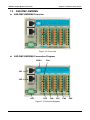
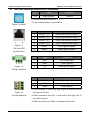
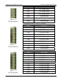
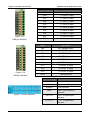
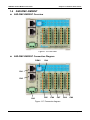
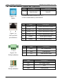
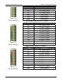
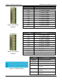
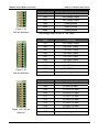
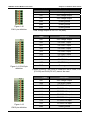
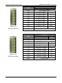
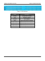
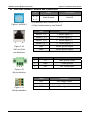
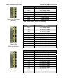
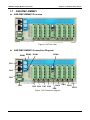
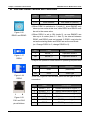
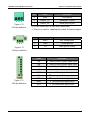
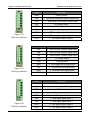
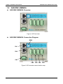
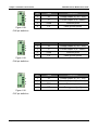
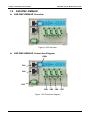
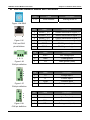
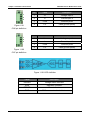
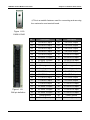
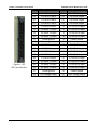
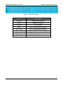
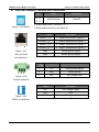
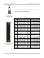
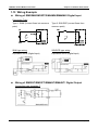
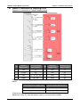
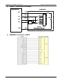
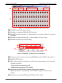
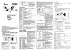
Chapter 1 Installation Environment DMCNET Remote Module User Guide ASD-DMC-RM64MN1 Module and Connectors Pin 1–9 A–F Figure 1.116 RSW1 Label Description Node Number Node ID ※Invalid when dial is turned to 0, D - F ※Each module takes up one Node ID Pin Label Description 1 RS485T_1(+) 1st RS485 transmission signal (+) 2 RS485T_1(-) 1st RS485 transmission signal (-) 3 RS485T_2(+) 2nd RS485 transmission signal (+) 6 RS485T_2(-) 2nd RS485 transmission signal (-) Figure 1.117 7 GND RS485 ground signal CN1 and CN2 8 GND RS485 ground signal 1 8 pin definitions 1 2 3 Pin Label Description 1 FG Case ground (earth) 2 GND Power ground 3 24V 24V voltage input Figure 1.118 CN3 pin definition Label Description 24V 24V voltage output COM Common input signal GND Power ground ※This connector is used with common point for Pull high or Figure 1.119 DSW1 pin definition Pull low ※COM connected with 24V (move to location marked 1) ➞ Low active (Pull high) ※COM connection with GND ➞ High active (Pull low) ※Total input voltage is 3.0A (Max) July 2014 1-47