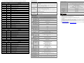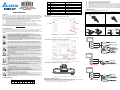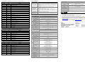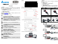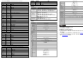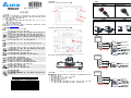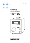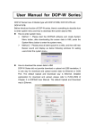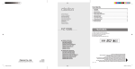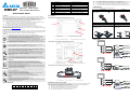
1
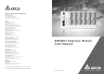
HMC07
‧
‧
High Color Motion Inside
User-Friendly HMI Products
Instrunction Sheet
(1)
Product Name
HMC: HMI with Controller
(2)
LCM Size
07: 7-inch TFT LCD
(3)
Type of Industries
N: General Purpose
(4)
Display Resolution
5: SVGA
(5)
Version
00
(6)
Type of Model
H: Handy (Hand-held) Type
Do not mount the HMI adjacent to heat-radiating elements or in direct sunlight.
Do not mount the HMI in a location subjected to corrosive gases, liquids, or airborne dust or metallic particles.
Do not mount the HMI in a location where temperatures and humidity will exceed specification.
Do not mount the HMI in a location where vibration and shock will exceed specification.
Do not mount the HMI in a location where it will be subjected to high levels of electromagnetic radiation.
(6) Wiring Method
、10、11
Be sure to perform wiring by referring to the following figures.
Before Wiring
Ensure to plug the power cable into the connector
(7)
External Control Interface (Bus)
5: DMCNET
(8)
Controller Remote Unit Interface
2: Specialized High-speed RS-422
(power supply connector) by following the
shown as below.
direction
After Wiring
After the wiring is completed, the connection will be
shown as the figure below.
(4) Parts Names
Thank you for purchasing DELTA’s HMC Series. This instruction sheet will be helpful in the installation, wiring and
inspection of Delta HMI product. Before using the product, please read this instruction sheet to ensure correct use. You
should thoroughly understand all safety precautions before proceeding with the installation, wiring and operation. Place
this instruction sheet in a safe location for future reference. Please observe the following precautions:
Install the product in a clean and dry location free from corrosive and inflammable gases or liquids.
Ensure that all wiring instructions and recommendations are followed.
Ensure that HMI is correctly connected to a ground. The grounding method must comply with the electrical
standard of the country (Please refer to NFPA 70: National Electrical Code, 2005 Ed.).
Do not disassemble HMI, modify or remove wiring when power is applied to HMI.
Do not touch the power supply during operation. Otherwise, it may cause electric shock.
If you have any questions during operation, please contact our local distributors or Delta sales representatives.
The content of this instruction sheet may be revised without prior notice. Please consult our distributors or download the
most updated version at http://www.delta.com.tw/ia
HMC07-N500H52 / HMC07-N510H52 / HMC07-N511H52 (Front View)
D
Note
A
(2) Safety Precautions
Note
Correctly connect RJ-45 connector to remote module
The height shall be 60 mm at least. Do not excessively
or ASDA servo drive.
bend the cable.
B
Carefully note and observe the following safety precautions when receiving, inspecting, installing, operating, maintaining
and troubleshooting. The following words, DANGER, WARNING and STOP are used to mark safety precautions when
using the Delta’s HMI product. Failure to observe these precautions may void the warranty!
Installation
Comply with quick start for installation. Otherwise it may cause equipment damage.
Do not install the product in a location that is outside the stated specification for the HMI. Failure to
observe this caution may result in electric shock, fire, or explosion.
Do not install the product in a location where temperatures will exceed specification for the HMI.
Failure to observe this caution may result in abnormal operation or damage the product.
Please note that this equipment has obtained EMC registration for commercial use. In the event that it
has been mistakenly sold or purchased, please exchange it for equipment certified for home use.
Do not use this product as an alarm device for disaster early warning that may result in personal injury,
equipment damage, or system emergency stop.
Wiring
X
C
A
Power LED Indicator
B
Auxiliary Function Keys (F1~F10)
C
Touch Screen / Display
D
Emergency Stop Switch
(7) Wring Types
HMC07-N500H52 / HMC07-N510H52 / HMC07-N511H52 (Rear View)
Connect the ground terminals to a class-3 ground (Ground resistance should not exceed 100Ω).
Improper grounding may result in communication error, electric shock or fire.
Operation
The users should use Delta program editor software, DOPSoft to perform editing in Delta's HMI
product. To perform editing and confirming HMI programs without using Delta program editor software,
DOPSoft in Delta's HMI product may result in abnormal operation.
To prevent the personal injury and equipment damage, when designing HMI programs, please ensure
that a communication error occurred between Delta’s HMI product and the connecting controller or
equipment will not result in system failure or malfunction.
Please be sure to backup the screen data and HMI programs in case they are lost, accidentally
deleted or worse.
A
Do not modify wiring during operation. Otherwise it may result in electric shock or personal injury.
Never use a hard or pointed object to hit or strike the screen as doing this may damage the screen and
let the screen has not respond at all, and then cause HMI to work abnormally.
Maintenance and Inspection
Do not touch any internal or exposed parts of the HMI as electrical shock may result.
Do not remove operation panel while power is on. Otherwise electrical shock may result.
Wait at least 10 minutes after power has been removed before touching any HMI terminals or
performing any wiring and/or inspection as an electrical charge may still remain in the HMI with
hazardous voltages even after power has been removed.
Turn the power off before changing backup battery and check system settings after finishing change.
(all data will be cleared after changing battery).
Be sure the ventilation holes are not obstructed during operation. Otherwise malfunction may result
due to bad ventilation or overheating troubles.
Wiring Method
Do not use a voltage that will exceed specification for the HMI. Failure to observe this caution may
result in electric shock or fire.
Remove the terminal block from the HMI before wiring.
Insert only one wire into one terminal on the terminal block.
If the wiring is in error, perform the wiring again with proper tools. Never use force to remove the
terminals or wires. Otherwise, it may result in malfunction or damage.
For the power line that forced to take out, ensure to check wiring again and restart.
Communication Wiring
Comply with communication wiring specification for wiring.
Wiring length should comply with the stated specification for the HMI.
Proper grounding to avoid bad communication quality.
To avoid noise and interference, the communication cable, all power cables, and motor power cable
should be placed in separate conduits.
B
A
3-Position Operation Switch
B
Cable Interface (Power Plug Connector)
HMC07-N500H52 / HMC07-N510H52 / HMC07-N511H52 (Top View)
A
A
USB Slave
B
C
B
USB Host
C
SD Card
(5) Installation and Storage Conditions
(3) Model Explanation
HMC
07
(1)
(2)
-
N
5
00
H
5
2
(3)
(4)
(5)
(6)
(7)
(8)
The product should be kept in the shipping carton before installation. In order to retain the warranty coverage, the HMI
should be stored properly when it is not to be used for an extended period of time. Some storage suggestions are:
Store in a clean and dry location free from direct sunlight.
Store within an ambient temperature range of -20°C to +60°C (-4°F to 140°F).
Store within a relative humidity range of 10% to 90% and non-condensing.
Do not store the HMI in a place subjected to corrosive gases and liquids.
Correctly packaged and placed on a solid and durable surface.
60 mm
(1) Preface
There are three wiring types for HMC07-N500H52: (a) 32 pin Type A; (b) 12 pin Type A; (c) 16 pin Type A
(8) Basic Inspection
Item
Content
(a) 32 pin Type A: HMC-CA3203A0 (3M), HMC-CA3205A0 (5M), HMC-CA3210A0 (10M)
Name
Explanation
White / Orange
EMG_C
Emergency stop switch b-contact
White / Orange
EMG_C
Emergency stop switch b-contact
White / Green
EMG_O
Emergency stop switch a-contact
White / Green
EMG_O
Red
Power
System power 24V+
Black
PGND
System power grounding
White
EGND
Earth grounding
Yellow
422_TX+
RS422: TX+, RS232: TX, RS485: T+/R+
White / Yellow
422_TX-
RS422: TX-, RS485: T-/R-
Black / White
CGND
Communication grounding
Black / White
CGND
Communication grounding
Black / White
CGND
Communication grounding
White / Blue
ENA_O
3-position operation switch a-contact
White / Blue
ENA_O
Purple
422_RX+
White / Purple
422_RX-
Black / Orange
INT1
General Inspection
Emergency stop switch a-contact
Inspection before
operation
(power is not applied)
Inspection before
operation
(power is applied)
Periodically inspect the screws of the connection between the HMI and device.
Tighten screws as necessary as they may loosen due to vibration and varying
temperatures.
Ensure that oil, water, metallic particles or any foreign objects do not fall inside
the HMI, control panel or ventilation slots and holes. As these will cause damage.
Ensure the correct installation and the control panel. It should be free from
airborne dust, harmful gases or liquids.
3-position operation switch a-contact
RS422: R+, RS232:RX
RS422: R-
7-inch TFT LCD
Resolution
800 x 600 pixels
Backlight
LED Back Light(less than 20,000 hours half-life at 25 C) (Note 1)
INT0
Display Size
141 x 105.75mm
Delta Real Time OS
External interrupt 0 input (Reserved)
7)
HMI
Red / Black
I_GND
White / Red
I_PW
External interrupt grounding (Reserved)
External interrupt power 24V+ (Reserved)
RJ45 Blue
DMC
DMCNET connection
RJ45 Black
ETH
Ethernet connection
RJ45 Green
RIO
Remote I/O connection
(b) 12 pin Type A: HMC-CA1203A0(3M), HMC-CA1205A0 (5M), HMC-CA1210A0 (10M)
Color
Name
White / Orange
EMG_C
Emergency stop switch b-contact
White / Orange
EMG_C
Emergency stop switch b-contact
White / Green
EMG_O
Emergency stop switch a-contact
White / Green
EMG_O
Emergency stop switch a-contact
Red
Power
System power 24V+
Black
PGND
System power grounding
White
EGND
Earth grounding
Black / White
CGND
Communication grounding
RJ45 Blue
DMC
32-bit RISC Micro-controller
MCU
Controller
32-bit DSP
NOR Flash ROM
Flash ROM 128 MB(OS System: 30MB / Backup: 16MB / User Application:
82MB)
SDRAM
64Mbytes
Backup Memory (Bytes)
16Mbytes
Sound
Effect
Output
Buzzer
(2K ~ 4K Hz)/85dB
Multi-Tone Frequency
AUX
N/A
Explanation
IEEE 802.3, IEEE 802.3u
Ethernet Interface
Memory Card
USB
Serial
COM
Port
(
10/100 Mbps auto-sensing (has built-in isolated power circuit (Note 3)
SD Card (supports SDHC)
1 USB Host (Note 2) Ver 1.1 / 1 USB Slave Ver 2.0
COM1
RS-232/RS-422/RS-485
(has built-in isolated power circuit
COM2
N/A
COM3
N/A
(Note 3)
Remote I/O
Specialized 10M bps RS-422
Motion Control Bus
DMCNET
)
DMCNET connection
Function Key
(c) 16 pin Type A: HMC-CA1603A0 (3M), HMC-CA1605A0 (5M), HMC-CA1610A0 (10M)
Color
Name
White / Orange
EMG_C
Emergency stop switch b-contact
Explanation
White / Orange
EMG_C
Emergency stop switch b-contact
White / Green
EMG_O
Emergency stop switch a-contact
White / Green
EMG_O
Emergency stop switch a-contact
Red
Power
System power 24V+
Black
PGND
System power grounding
White
EGND
Emergency Stop
Switch
Key /
Switch
3-Position Operation
Switch
10 function keys
Push-lock switch 2 contacts
a-contact (normally open): 1 contact
b-contact (normally closed): 1 contact
Rated voltage: DC30V
Maximum rated current: 500mA
Minimum allowable load: DC5V, 1mA
Output switch 1 contact
a-contact (normally open): 1 contact
Rated voltage: DC30V
Maximum rated current: 500mA
Minimum allowable load: DC3V, 1mA
Perpetual Calendar
Built-in
Earth grounding
Cooling Method
Natural air circulation
Communication grounding
Safety Approval
CGND
RJ45 Blue
DMC
DMCNET connection
RJ45 Green
RIO
Remote I/O connection
Operation Voltage (Note5)
Voltage Endurance
Power Consumption
(Note 5)
CE
/UL
(Note 4)
/KCC
(Note 4)
DC +24V(-10% ~ +15%)
(has built-in isolated power circuit
(Note 3)
)
AC500V for 1 minute (between charging (DC24V terminal)
and FG terminals)
8W
Backup Battery
3V lithium battery CR2032 x 1
Backup Battery Life
It depends on the temperature used and the conditions of usage,
o
about 3 years or more at 25 C.
)
o
o
o
o
o
10% ~ 90% RH [0 ~ 40 C], 10% ~ 55% RH [41 ~ 50 C]
Pollution Degree 2
IEC 61131-2 compliant
≦<
≦≦
5Hz f 8.3Hz = Continuous: 3.5mm,
8.3Hz f 150Hz = Continuous: 1.0g
IEC 60068-2-27 compliant 15g peak for 11 ms duration
X, Y, Z directions for 6 times
238 x 199 x 129
(Emergency stop switch and projection are included.)
219.4 X 166.5
Approx.1500g
NOTE
6)
External interrupt 1 input (Reserved)
Black / White
Weight
5)
o
Operation System
Black / Green
Dimensions
(W) x (H) x (D) mm
Panel Cutout
(W) x (H) mm
2)
3)
4)
(65536 colors)
-20 C ~ +60 C
Shock
(9) Specifications
Display Type
Storage Temperature
Vibration
Check if power LED lights.
Check if the communication among devices is normal.
Please contact our local distributors or Delta sales representative if there are any
abnormal conditions.
HMC07-N500H52 / HMC07-N510H52 / HMC07-N511H52
0 C ~ 50 C
Ambient Humidity
Ensure that all wiring terminals are correctly insulated.
Ensure that all wiring is correct or damage and or malfunction may result.
Visually check to ensure that there are not any unused screws, metal strips, any
conductive or inflammable materials inside HMI.
Ensure to lower electromagnetic interference when devices are influenced by it.
Ensure that the external applied voltage to HMI is correct and matched to the
controller.
MODEL
HMC07-N500H52 / HMC07-N510H52 / HMC07-N511H52
o
1)
LCD MODULE
Color
MODEL
Operation Temperature
The half-life of backlight is defined as original luminance being reduced by 50% when the maximum driving current
o
is supplied to HMI. The life of LED backlight shown here is an estimated value under 25 C normal temperature and
humidity conditions.
USB Host port can provide up to 5V/ 500mA of power.
The withstand voltage of the isolated power circuit is 1500V peak for 1 minute.
Some models are in the process of application to UL and KCC certification. For more information, please consult
our distributors.
The value of the power consumption indicates the electrical power consumed by HMI only without connecting to
any peripheral devices. In order to ensure the normal operation, it is recommended to use a power supply which
the capacity is 1.5 ~2 times the value of the power consumption.
Users can download the DOPSoft, the program editor of Delta HMI product and the user manual via the following
link: http://www.delta.com.tw/ia.
The content of this instruction sheet may be revised without prior notice. Please consult our distributors or
download the most updated version at http://www.delta.com.tw/ia .
‧
Yüksek Renk Motion
İçerikli Kullanımı Kolay
HMI Ürünleri
Bilgi Dökümanı
10% - 90% rutubet aralığında ve yoğuşmasız ortamda saklanmalıdır.
HMI aşındırıcı sıvı ve gaz bulunan ortamlarda saklanmamalıdır.
Ürün uygun paketlenmeli, sert ve düz bir yüzeyde saklanmalıdır.
HMI doğrudan güneş ışığının temas ettiği yerlere ya da ısı yayan nesnelerin yakınına montajı yapılmamalıdır.
HMI aşındırıcı gaz ve sıvının olduğu toz veya metal parçacıkların bulunduğu yerlere montajı yapılmamalıdır.
HMI dokümanda belirtilen sıcaklık ve rutubet oranları dışında ortamlara montajı yapılmamalıdır.
HMI dokümanda belirtilen titreşim ve şok oranlarının üzerindeki ortamlara montajı yapılmamalıdır.
HMI yüksek seviyede elektromanyetik radyasyonun bulunduğu ortamlara montajı yapılmamalıdır.
Ürün Adı
HMC: Kontrolörlü HMI
(2)
LCM Boyutu
07: 7-inch TFT LCD
(3)
Endüstri Tipi
N: Genel Amaçlı
(4)
Ekran Çözünürlüğü
5: SVGA
(5)
Versiyon
00
(6)
Model Tipi
H: Elde Taşınabilen Tip
(6) Bağlantı Metodu
Bağlantının aşağıdaki şekilde gösterildiği gibi yapıldığına emin olunuz.
Bağlantıdan Önce
、10、11
(7)
Harici Kontrol Arabirimi (Bus)
5: DMCNET
(8)
Kontrolör Uzak Ünite Arabirimi
2: Özelleştirilmiş Yüksek-hızlı RS-422
Fişin konnektöre (güç kaynağı konnektörü) aşağıda
gösterilen
(1) Önsöz
DELTA’nın HMC serisi operatör panellerini seçtiğiniz için teşekkürler. Bu bilgi dokümanı Delta HMI kurulum, bağlantı,
bakım ve kontrolünde kullanıcıya yardımcı olacaktır. Doğru kullanım için ürünü kullanmadan önce bu dokümanı mutlaka
okuyunuz. Kurulum, bağlantı ve çalışma yapmadan önce güvenlik uyarılarını tamamen anladığınızdan emin olunuz. Bu
dokümanı daha sonra da kullanmak için iyi muhafaza ediniz. Lütfen aşağıdaki güvenlik uyarılarına dikkat ediniz:
Ürünün kurulumunu yanıcı gaz ve sıvılardan uzak kuru ve temiz ortamlara yapınız.
Bağlantıları yaparken tüm bağlantı kurallarının sağlandığından emin olunuz.
HMI’nın toprak bağlantısının doğru yapıldığından emin olunuz. Topraklama metodunun ürünün kurulduğu ülke
standartlarına uygun olduğuna emin olunuz. (NFPA 70: National Electrical Code, 2005 Ed.).
HMI enerjili iken kablo bağlantısı yapmayınız ya da sökmeyiniz.
Çalışma sırasında enerji besleme terminallerine dokunmayınız. Aksi halde elektrik şoku olabilir.
Ürünün kullanımı ile ilgili sorularınız için, lütfen teknik servisimizle bağlantıya geçiniz. Herhangi bir ihbara gerek
kalmaksızın bu bilgi dokümanının içeriği değiştirilebilir. Güncellenmiş versiyonu elde etmek için teknik servise danışabilir
veya internet adresinden indirebilirsiniz. http://www.delta.com.tw/ia
yönde takılmasını sağlayınız.
(4) Parça Adları
HMC07-N500H52 / HMC07-N510H52 / HMC07-N511H52 (Ön Görünüm)
D
A
Not
RJ-45 konnektörü uzak modüle veya ASDA servo
sürücüye düzgünce bağlayınız.
(2) Güvenlik Uyarıları
B
Ürünü alırken, kontrol ederken, kurulumunu yaparken, çalıştırırken, bakım ve arıza teşhisi yaparken aşağıdaki güvenlik
uyarılarına dikkat ediniz. DANGER, WARNING, ve STOP başlıkları DELTA HMI ürününü kullanırken yapılması
gerekenleri dikkat çekmek için kullanılmıştır. Ürünün garantisini muhafaza etmek için bu uyarılara mutlaka dikkat ediniz!
Kurulum
Kurulumu doküman da belirtildiği gibi yapınız. Aksi halde ürün zarar görebilir.
Operatör panelini doküman da belirtilen ortam değerlerinin dışında kurulumunu yapmayınız. Aksi
halde elektrik şoku, yangın ya da kişisel zararlara sebep olabilir.
HMI ürününü bu doküman da belirtilen sıcaklık değerleri dışında bir ortama kurulumunu yapmayınız.
Aksi halde anormal çalışma olabilir veya ürün zarar görebilir.
DELTA HMI ürünleri endüstriyel uygulamalarda kullanılmak amacıyla tasarlanmıştır.
Bu ürün endüstriyel otomasyon uygulamaları için geliştirilmiştir. Farklı bir amaç için (erken uyarı alarm
sistemleri gibi) kullanılması tavsiye edilmez.
Bağlantı
A
Power LED Göstergesi
B
Harici Fonksiyon Tuşları (F1~F10)
C
Dokunmatik Ekran / Display
D
Acil Stop Anahtarı
(7) Bağlantı Tipleri
HMC07-N500H52 / HMC07-N510H52 / HMC07-N511H52 (Arka Görünüm)
Çalışma
DELTA’nın HMI ürünlerini programlamak için DOPSoft yazılımı kullanılmalıdır. DELTA HMI ürünlerini
programlamak için DOPSoft yazılımı dışında bir yazılım kullanılması durumunda HMI çalışmasında
problem meydana gelebilir.
Kişisel tehlikeleri ve ürünün zarar görmesini önlemek için, HMI programları oluştururken, DELTA HMI
ile ona bağlı kontrol ünitesi veya donanım arasında haberleşme hatası olduğunda sistemin zarar
görmemesi ve bozulmaması için gerekli önlemler alınmalıdır.
Kaza ile silinme, kaybolma... vb durumlara karşı ekran datalarının ve HMI programlarının yedeğini
aldığınıza emin olunuz.
(3) Model Açıklaması
A
B
A
3-Pozisyonlu Çalışma Anahtarı
B
Kablo Arabirimi (Güç Kaynağı
Konnektörü)
HMC07-N500H52 / HMC07-N510H52 / HMC07-N511H52 (Üst Görünüm)
A
A
USB Slave
B
C
B
USB Host
C
SD Card
(5) Kurulum ve Saklama Koşulları
HMC
07
(1)
(2)
-
N
5
00
H
5
2
(3)
(4)
(5)
(6)
(7)
(8)
Kurulum yapılana kadar ürün orijinal kutusu içinde muhafaza edilmelidir. Ürünün garanti kapsamının devamı için, ürün
belli bir süre kullanılmayacaksa, HMI uygun bir şekilde saklanmalıdır. Bazı saklama önerileri:
Doğrudan güneş ışığının temas etmediği kuru ve temiz ortamda saklanmalıdır.
-20°C - +60°C (-4°F - 140°F) sıcaklık aralığında saklanmalıdır.
Not
Yüksekliği en az 60mm olmalıdır. Kabloyu aşırı
bükmeyin.
X
C
Toprak terminallerini class-3 topraklama yapınız. (Topraklama direnci 100Ω‘u aşmamalıdır). Yanlış
yapılan topraklama bağlantısı haberleşme hatasına, elektrik şokuna ve yangına sebep olabilir.
Çalışma sırasında kablo bağlantılarını değiştirmeyiniz. Aksi halde elektrik şokuna veya kişisel
zararlara sebep olabilir.
Dokunmatik ekrana sert ve sivri nesneler kullanarak basmayınız. Aksi halde HMI ekranı zarar görebilir
ve HMI’nın anormal çalışmasına sebep olabilir..
Bakım ve Kontroller
HMI içindeki devre elemanlarına dokunmayınız aksi halde elektrik şoku meydana gelebilir.
Enerjili iken operatör panelinin bağlantılarına müdahale etmeyiniz. Aksi halde elektrik şoku meydana
gelebilir.
HMI enerjisi kesildikten sonra HMI üzerinde tehlikeli seviyede elektrik şarj voltajı kalabileceğinden
ürüne dokunmadan ve bağlantılara müdahale etmeden önce en az 10 dakika beklenilmesi tavsiye
edilir.
Pili değiştirmeden önce ürünün enerjisini kesiniz ve pili değiştirdikten sonra sistem ayarlarını kontrol
ediniz. (Pil değiştirildikten sonra tüm datalar silinecektir).
Çalışma sırasında havalandırma deliklerinin tıkalı olmadığından emin olunuz. Aksi halde kötü
havalandırmadan veya aşırı sıcaklıktan dolayı ürün zarar görebilir.
Bağlantı Metodu
HMI için bu dokümanda belirtilen değerlerin dışında voltaj uygulamayınız. Aksi halde elektrik şoku
veya yangına sebep olabilir.
Kablo bağlantısı yapmadan önce terminal bloğunu HMI’ dan ayırınız.
Terminal bloğundaki her bir terminale sadece tek bir kablo bağlayınız.
Eğer bağlantıda hata varsa, bağlantıyı uygun aletleri kullanarak tekrar yapınız. Terminal ya da
kabloları sökmek için darbe uygulamayınız. Aksi halde ürün zarar görebilir.
Haberleşme Bağlantısı
Haberleşme bağlantısını doküman da belirtildiği gibi yapınız.
HMI Kablo uzunlukları doküman da belirtildiği gibi olmalıdır.
Haberleşmenin kalitesini arttırmak için düzgün topraklama yapınız.
Gürültü ve parazitten kaçınmak için, haberleşme kablosu, tüm enerji besleme kabloları ve motor
kablolarından ayrı olmalıdır.
Bağlantıdan Sonra
Kablolama tamamlandıktan sonra bağlantı aşağıda
şekilde gösterildiği gibi olacaktır.
60 mm
‧
HMC07
(1)
HMC07-N500H52 için 3 tip bağlantı mevcuttur: (a) 32-pin Tip A; (b) 12-pin Tip A; (c) 16-pin Tip A
(8) Temel Denetimler
Madde
(a) 32-pin Tip A: HMC-CA3203A0 (3M), HMC-CA3205A0 (5M), HMC-CA3210A0 (10M)
Renk
Açıklama
Açıklama
İsim
Beyaz / Turuncu
EMG_C
Acil stop anahtarı b-kontak
Beyaz / Turuncu
EMG_C
Acil stop anahtarı b-kontak
Beyaz / Yeşil
EMG_O
Acil stop anahtarı a-kontak
Beyaz / Yeşil
EMG_O
Acil stop anahtarı a-kontak
Kırmızı
Power
Sistem beslemesi 24V+
Siyah
PGND
Sistem beslemesi sıfırı
Beyaz
EGND
Koruma topraklaması
Sarı
422_TX+
RS422: TX+, RS232: TX, RS485: T+/R+
Beyaz / Sarı
422_TX-
RS422: TX-, RS485: T-/R-
Genel Denetimler
Çalışma öncesi
denetimler(enerji
uygulanmadan önce)
Siyah / Beyaz
CGND
Haberleşme sıfırı
Siyah / Beyaz
CGND
Haberleşme sıfırı
Siyah / Beyaz
CGND
Haberleşme sıfırı
Beyaz / Mavi
ENA_O
3-pozisyonlu çalışma anahtarı a-kontak
ENA_O
Mor
422_RX+
RS422: R+, RS232:RX
Beyaz / Mor
422_RX-
RS422: R-
Siyah / Turuncu
INT1
Harici interrupt 1 girişi (Rezerve)
Siyah / Yeşil
INT0
Harici interrupt 0 girişi (Rezerve)
Kırmızı / Siyah
I_GND
Display Tipi
Ethernet bağlantısı
RJ45 Yeşil
RIO
Uzak I/O bağlantısı
Aydınlatma
LED Aydınlatma(25 C yarım ömürde 20,000 saatten az) (Not 1)
Display Ölçüsü
141 x 105.75mm
Renk
İsim
EMG_C
Acil stop anahtarı b-kontak
Beyaz / Turuncu
EMG_C
Acil stop anahtarı b-kontak
Beyaz / Yeşil
EMG_O
Acil stop anahtarı a-kontak
Delta Real Time OS
32-bit RISC Micro-controller
NOR Flash ROM
SDRAM
64Mbyte
Backup Hafıza (Byte)
16Mbyte
Ses
Efekti
Çıkışı
Açıklama
Buzzer
(
)/85dB
Multi-Tone Frekansı 2K ~ 4K Hz
AUX
N/A
IEEE 802.3, IEEE 802.3u
Ethernet Arabirimi
Hafıza Kartı
USB
COM1
Seri
COM
Port
Acil stop anahtarı a-kontak
32-bit DSP
10/100 Mbps otomatik algılamalı
(dahili izoleli güç devresi mevcut (Not 3)
)
SD Card (SDHC destekler)
(Not 2)
1 USB Host
Ver 1.1 / 1 USB Slave Ver 2.0
RS-232/RS-422/RS-485
(dahili izoleli güç devresi mevcut
COM2
N/A
COM3
N/A
)
(Not 3)
Beyaz / Yeşil
EMG_O
Kırmızı
Power
Sistem beslemesi 24V+
Siyah
PGND
Sistem beslemesi sıfırı
Uzak I/O
Özelleştirilmiş 10Mbps RS-422
Motion Kontrol Bus
DMCNET
Beyaz
EGND
Koruma topraklaması
Siyah / Beyaz
CGND
Haberleşme sıfırı
RJ45 Mavi
DMC
Fonksiyon Tuşları
DMCNET bağlantısı
Acil Stop Anahtarı
(c) 16-pin Tip A: HMC-CA1603A0 (3M), HMC-CA1605A0 (5M), HMC-CA1610A0 (10M)
Renk
İsim
Açıklama
Beyaz / Turuncu
EMG_C
Acil stop anahtarı b-kontak
Beyaz / Turuncu
EMG_C
Acil stop anahtarı b-kontak
Beyaz / Yeşil
EMG_O
Acil stop anahtarı a-kontak
Beyaz / Yeşil
EMG_O
Acil stop anahtarı a-kontak
Tuş /
Anahtar
3-Pozisyonlu Çalışma
Anahtarı
10 fonksiyon tuşu
Basma kilitlemeli 2 kontaklı anahtar
a-kontak (normalde açık): 1 kontak
b-kontak (normalde kapalı): 1 kontak
Voltaj aralığı: DC30V
Maksimum akım aralığı: 500mA
Minimum izin verilen yük: DC5V, 1mA
Çıkış anahtarı 1 kontak
a-kontak (normalde açık): 1 kontak
Voltaj aralığı: DC30V
Maksimum akım aralığı: 500mA
Minimum izin verilen yük: DC3V, 1mA
Kalıcı Takvim
Kırmızı
Power
Sistem beslemesi 24V+
Soğutma Metodu
Siyah
PGND
Sistem beslemesi sıfırı
Güvenlik Onayı
Beyaz
EGND
Koruma topraklaması
Çalışma Voltajı (Not5)
Siyah / Beyaz
CGND
Haberleşme sıfırı
RJ45 Mavi
DMC
DMCNET bağlantısı
RJ45 Yeşil
RIO
Uzak I/O bağlantısı
Voltaj Dayanımı
Dahili
Doğal hava sirkülasyonu
CE
/UL
(Not 4)
/KCC
(Not 4)
DC +24V(-10% ~ +15%)
(dahili izoleli güç devresi mevcut
)
(Not 3)
1 dakika için AC500V
(DC24V besleme terminalleri ve FG terminalleri arasında)
Güç Tüketimi (Not 5)
8W
Backup Pili
3V lityum pil CR2032 x 1
Backup Pil Ömrü
Kullanım koşulları ve ortam sıcaklığına bağlı olarak
o
25 C’de yaklaşık 3 yıl veya üzeri.
Çalışma Sıcaklığı
0 C ~ 50 C
o
o
HMC07-N500H52 / HMC07-N510H52 / HMC07-N511H52
-20 C ~ +60 C
o
o
o
Rutubet Oranı
Titreşim
Şok
Ölçüler
(W) x (H) x (D) mm
Panel Kesim Ölçüsü
(W) x (H) mm
Ağırlık
o
10% ~ 90% RH [0 ~ 40 C], 10% ~ 55% RH [41 ~ 50 C]
Kirlenme Derecesi 2
IEC 61131-2 uyumlu 5Hz f 8.3Hz = Sürekli: 3.5mm,
8.3Hz f 150Hz = Sürekli: 1.0g
IEC 60068-2-27 uyumlu 11ms süresince 15g pik,
X, Y, Z yönünde 6 defa
238 x 199 x 129
(Acil stop anahtarı ve izdüşümü dahil edilmiştir.)
≦≦
≦<
219.4 X 166.5
Yaklaşık.1500g
NOTE
1)
2)
3)
4)
5)
6)
7)
Flash ROM 128 MB(OS Sistem: 30MB / Backup: 16MB / Kullanıcı Uygulaması:
82MB)
(b) 12-pin Tip A: HMC-CA1203A0(3M), HMC-CA1205A0 (5M), HMC-CA1210A0 (10M)
Beyaz / Turuncu
o
Kontrolör
Harici interrupt besleme 24V+ (Rezerve)
DMCNET bağlantısı
(65536 renk)
800 x 600 piksel
HMI
I_PW
ETH
7-inch TFT LCD
Çözünürlük
MCU
Beyaz / Kırmızı
DMC
HMC07-N500H52 / HMC07-N510H52 / HMC07-N511H52
İşletim Sistemi
Harici interrupt sıfırı (Rezerve)
RJ45 Mavi
MODEL
3-pozisyonlu çalışma anahtarı a-kontak
RJ45 Siyah
(9) Özellikler
LCD MODULÜ
Beyaz / Mavi
Çalışma öncesi
denetimler(enerji
uygulandıktan sonra)
HMI ve donanım arasındaki bağlantı vidalarını periyodik olarak kontrol ediniz.
Titreşim ve sıcaklık değişiminden dolayı gevşeyen vidaları sıkınız.
HMI içine, kontrol paneline veya havalandırma slot ve deliklerine yağ, su, metal
parçalar veya yabancı nesnelerin düşmediğine emin olunuz. Bu durum ürüne
zarar verir.
Kurulumu doğru yaptığınıza emin olunuz. Ortamda toz, zararlı gaz ve sıvılar
olmamalıdır.
Tüm bağlantı terminallerinin doğru izole olduğundan emin olunuz.
Zarar ve hasar meydana gelmemesi için tüm bağlantıların doğru yapıldığına emin
olunuz.
HMI içinde kullanılmayan vidaların, metal parçaların, iletken veya yanıcı
maddelerin olmadığını gözle kontrol ediniz.
Ürünü etkileyebilecek elektromanyetik gürültünün düşük olduğuna emin olunuz.
HMI ünitesine uygulanan harici voltajın doğru ve ürüne uygun olduğunu kontrol
ediniz.
Power LED ışığının yandığını kontrol ediniz.
Cihazlar arasında haberleşmenin normal olduğunu kontrol ediniz.
Anormal bir durum ile karşılaştığınızda teknik servisimizle bağlantıya geçiniz.
MODEL
Saklama Sıcaklığı
Arka ışık yarım-ömrü, HMI maksimum akımla beslendiğinde orijinal aydınlatmanın %50 düşürüldüğü anlamına gelir.
o
Yukarıda gösterilen arka ışık LED aydınlatma ömrü 25 C ‘de derecede normal sıcaklık ve rutubet ortamında tahmin
edilen değerlerdir.
USB Host port 5V/ 500mA ‘e kadar güç sağlayabilir.
İzole edilmiş güç devresinin dayanma voltajı 1 dakika için 1500V pik değerindedir.
Bazı modeller UL ve KCC başvuru sürecindedir. Daha fazla bilgi için firmamız ile temasa geçiniz.
Güç tüketimi HMI ünitesinin hiç bir cihaza bağlı olmadan boş olarak tükettiği gücü gösterir. Normal çalışmada
HMI’nın boş iken tükettiği gücün 1,5 veya 2 katı güç verebilen besleme kaynağı kullanılması tavsiye edilir.
Delta HMI ürünleri program editörü DOPSoft ve kullanım kılavuzlarını aşağıdaki linkten yükleyebilirsiniz:
http://www.delta.com.tw/ia.
Herhangi bir ihbar olmadan bu dokümanın içeriği değiştirilebilir. En son güncellenmiş halini firmamızdan talep
edebilir ya da aşağıdaki link adresinden indirebilirsiniz. http://www.delta.com.tw/ia
(3)
型號說明
HMC
(1)
安裝說明
(1)
一般注意事項
感謝您使用本產品,本人機介面安裝說明書提供 HMC 系列人機介面的相關資訊。在使用之前,請您仔細詳讀本說明書以
確保使用上的正確。此外,請妥善將其放置在明顯的地點以便隨時查閱。下列事項在您尚未讀完本說明書前,請務必遵守:
安裝的環境必須沒有水氣,腐蝕性氣體及可燃性氣體。
接線時,請依接線圖說明施工。
接地工程必須確實實施,接地時須遵照國家現行相關電工法規之規定施行(請參考 NFPA 70: National Electrical
Code, 2005 Ed.)。
在通電時,請勿拆解人機介面或更改配線。
在通電運作時,請勿接觸電源處,以免觸電。
如果您在使用上仍有問題,請洽詢經銷商或者本公司客服中心。由於產品精益求精,當內容規格有所修正時,請洽詢代理
商或至台達網站(http://www.delta.com.tw/ia)下載最新版本。
(2)
(4)
各部位說明
-
N
(3)
5
(4)
產品系列名稱
LCM 尺寸別
行業類別
顯示規格
版本識別碼
機種代碼
控制器外部控制介面(總線)
控制器 Remote Unit 介面
(1)
(2)
(3)
(4)
(5)
(6)
(7)
(8)
00
(5)
H
(6)
5
(7)
HMC: HMI with Controller
07: 7
TFT LCD
N:
5: SVGA
00 10 11
H: Hand (
)
5: DMCNET
2:
RS-422
吋
泛用
、 、
手持式
專用高速
操作注意
保養及檢查
A
配線方法
通訊電路的配線
接線方式
接線後
下圖為已接線完成的樣式
B
C
A
C
電源指示燈
操作/顯示區域
B
輔助鍵(F1~F10)
D
緊急停止按鈕
注意事項
注意事項
依據 RJ-45 接頭正確方向,接上 Remote 模組 接線高度至少 60 mm,不要過度折彎
或 ASDA Servo Driver
X
(背面)
HMC07-N500H52 / HMC07-N510H52 / HMC07-N511H52
(7)
人機介面需配合編輯軟體規劃畫面,未經規劃或確認之人機介面可能會導致不正常運轉結果。為避免操
作人身傷害或設備損壞,規劃人機畫面時,要確保人機介面及其連接控制器或設備之間的通訊故障不會
造成設備功能無法正常運作。
為避免意外遺失程式,請務必備份規劃好的人機介面畫面程式。
不得在開啟電源情況下改變配線,否則可能造成觸電或人員受傷。
請勿以尖銳物品碰觸面板,否則可能導致面板凹陷,進而無法使人機介面正常運作。
A
A
三段式操作按鈕
接線槽
B
B
(俯視面)
HMC07-N500H52 / HMC07-N510H52 / HMC07-N511H52
請勿使用超過人機介面規格範圍的電壓,否則可能會引起觸電或火災。
配線時請將快速接頭從人機介面的本體上拆下來。
快速接頭的一個電線插入口,請僅插入一根電線。
對於錯誤強行拔出電線的動作,請重新檢查連接電線再啟動。
請依標準規格採用通訊配線線材。
通訊線材長度需在符合規定內。
採用正確的接地迴路,以避免通訊不良。
為防止較大的雜訊干擾引起人機介面無法正常運作,請用單獨的配線槽將人機介面的通訊電纜和所有電
源線及馬達動力線分開。
(6)
D
請將接地端子連接到 class-3(100Ω 以下)接地,接地不良可能會造成通訊異常、觸電或火災。
禁止接觸人機介面內部,否則可能會造成觸電。
電源啟動時,禁止拆下人機介面面板,否則可能會造成觸電。
電源關閉 10 分鐘內,不得接觸接線端子,殘餘電壓可能造成觸電。
更換備用電池時,應切斷電源再進行,並在更換後重新檢查系統設定值。
人機介面在操作時,排氣孔不可封住,否則人機容易因為散熱不良而造成故障。
安裝環境條件
接線前
請將配線上的 對準接線槽插入
(正面)
HMC07-N500H52 / HMC07-N510H52 / HMC07-N511H52
安全注意事項
安裝、配線、操作、維護及檢查時,應隨時注意以下安全注意事項。
安裝注意
依照手冊指定的方式安裝人機介面,否則可能導致設備損壞。
禁止將本產品暴露在有水氣、腐蝕性氣體、可燃性氣體等物質的場所下使用,否則可能會造成觸電、火
災或爆炸。
請勿將人機介面安裝在超過規格範圍的溫度環境中,否則可能造成人機介面無法正常運作或損壞。
本產品為 KCC Class A(商用設備)產品且通過試驗認證,其設計的目的是在商業或是工業環境使用,
而非家庭環境中使用。若在此情況下不小心購買或售出人機介面產品,請將其更換為有符合 KCC Class
B(家用設備)認證之產品。
請勿將人機介面用於可能會造成人員傷亡、設備損壞或系統停機等警報機台。
配線注意
(5)
本產品在安裝之前必須置於其包裝箱內,若暫時不使用,為了使該產品能夠符合本公司的保固範圍及日後的維護,儲存時
務必注意下列事項:
必須置於無塵垢、乾燥之位置。
儲存位置的環境溫度必須在-20°C to +60°C (-4°F to 140°F) 範圍內。
儲存位置的相對溼度必須在 10%到 90%範圍內,且無結露。
避免儲存於含有腐蝕性氣、液體之環境中。
最好適當包裝存放在架子或台面。
本產品適合的安裝環境包括有:無發高熱裝置之場所;無水滴、蒸氣、灰塵及油性灰塵之場所;無腐蝕、易燃性
之氣、液體之場所;無漂浮性的塵埃及金屬微粒之場所;堅固無振動、無電磁雜訊干擾之場所。
2
(8)
A
A
USB Slave
B
B
C
USB Host
C
SD Card
配線種類
60 mm
HMC07
高彩‧可控制‧友善人機介面
07
(2)
為三種配線:(a) 32 pin Type A; (b) 12 pin Type A; (c) 16 pin Type A
32 pin Type A:HMC-CA3203A0 (3M)、HMC-CA3205A0 (5M)、HMC-CA3210A0 (10M)
線條名稱
編號名稱
說明
白/橘
EMG_C
緊急開關 B 接點
白/橘
EMG_C
緊急開關 B 接點
白/綠
EMG_O
緊急開關 A 接點
白/綠
EMG_O
緊急開關 A 接點
紅
Power
系統電源 24V+
黑
PGND
系統電源接地
白
EGND
大地接地
線條名稱
黑 /白
HMC07-N500H52 共分
(a)
黃
白/黃
422_TX-
黑 /白
CGND
RS422: TX-, RS485: T-/R-
白 /藍
ENA_O
紫
422_RX+
RS422: R+, RS232:RX
黑 /白
白 /藍
白 /紫
黑 /橘
黑 /綠
紅 /黑
CGND
CGND
ENA_O
422_RXINT1
INT0
I_GND
白 /紅
I_PW
RJ45 藍
DMC
RJ45 黑
ETH
RJ45 綠
RIO
12 pin Type A
線條名稱
白 /橘
白 /橘
白 /綠
白 /綠
紅
黑
白
黑 /白
RJ45 藍
(c)
RS422: TX+, RS232: TX, RS485: T+/R+
通訊接地
通訊接地
通訊接地
三段式操作關關 A 接點
三段式操作關關 A 接點
黑 /白
(b)
422_TX+
16 pin Type A
線條名稱
白 /橘
白 /橘
白 /綠
白 /綠
紅
黑
白
(8)
:HMC-CA1203A0(3M)、HMC-CA1205A0 (5M)、HMC-CA1210A0 (10M)
編號名稱
說明
EMG_C
緊急開關 B 接點
EMG_C
緊急開關 B 接點
EMG_O
緊急開關 A 接點
EMG_O
緊急開關 A 接點
Power
系統電源 24V+
PGND
系統電源接地
EGND
大地接地
CGND
通訊接地
DMC
DMCNet 接線
:HMC-CA1603A0 (3M)、HMC-CA1605A0 (5M)、HMC-CA1610A0 (10M)
編號名稱
說明
EMG_C
緊急開關 B 接點
EMG_C
緊急開關 B 接點
EMG_O
緊急開關 A 接點
EMG_O
緊急開關 A 接點
Power
系統電源 24V+
PGND
系統電源接地
EGND
大地接地
CGND
RJ45 藍
DMC
RJ45 綠
RIO
基本檢測
檢測項目
一般檢測
操作前檢測
(未供應控制電源)
運轉前檢測
(已供應控制電源)
(9)
硬體規格
型號
面板種類
解析度
RS422: R-
外部中斷 1 輸入(保留)
外部中斷 0 輸入(保留)
外部中斷接地(保留)
外部中斷電源 24V+(保留)
DMCNet 接線
Ethernet 接線
RemoteIO 接線
編號名稱
顯
示
器
背光燈
顯示範圍
作業系統
中央處 HMI
理器 控制器
記憶體 ROM
音
效
輸
說明
通訊接地
三段式操作按鈕
接線
RemoteIO 接線
DMCNet
HMC07-N500H52 / HMC07-N510H52 / HMC07-N511H52
7”TFT LCD(65536 色)
(常溫 25 C 下半衰期>2 萬小時)
o
LED Back Light
Flash ROM 128 MB(OS System: 30MB / Backup: 16MB / User Application: 82MB)
(W)x(H)x(D)
自然冷卻
/KCC (Note 4)
CE/UL (Note 4)
(-10% ~ +15%)
(內建隔離電路 )
DC24 端子與 FG 端子間:AC500V, 1 分鐘
DC +24V
(Note 3)
8W
電池 CR2032 × 1
依使用環境溫度及使用條件而不同,常溫 25 C 下壽命約三年以上
3V 鋰
o
o
o
0 C ~ 50 C
o
o
-20 C ~ +60 C
10% ~ 90% RH【0 ~ 40 C】
o
,10% ~ 55% RH【41 ~ 50 C】,污染等級 2
o
規定連續震動 5Hz~8.3Hz 3.5mm, 8.3Hz~150Hz 1G
IEC60068-2-27 規定耐衝擊 11ms, 15G Peak, X, Y, Z 方向各 6 次
IEC61131-2
238 x 199 x 129 (含緊急開
關 高度 )
mm
重量
約 1500 g
NOTE
(2K ~ 4K Hz)/85dB
N/A
IEEE 802.3, IEEE 802.3u
(內建隔離電路
(Note 3)
)
SD 卡(支援 SDHC)
1 USB Host (
) Ver 1.1 / 1 USB Slave Ver 2.0
RS-232 / RS-422/ RS-485
(Note 2
(內建隔離電路
COM2
N/A
COM3
N/A
(Note 3)
)
專用 10M bps RS-422
運動控制總線
DMCNET
輔助鍵
總線
10 function keys
Push-lock switch
Output: 2 contacts
接點 (normally open): 1
接點 (normally closed): 1
額定電壓:DC 30V
最大額定電流:500mA
最小適用負載:DC 5V/1mA
A
B
背光模組半衰期的定義:最大驅動電流下,背光亮度衰退到最大亮度的一半時,即為半衰期。
所標示之壽命時間為 25 oC 常溫常濕工作環境下之預估值。
USB Host 最大可提供 5V/ 500mA 電源。
隔離電路耐受規格:可承受 1 分鐘 1500V 高壓突波。
部份機種認證申請中,詳細認證機種請洽詢各區域代理商。
消耗功率為無外接週邊設備時,人機本體所消耗的功率。建議選用的電源供應器容量為標示消耗功率之 1.5~2 倍,以
確保人機工作正常。
系列編輯軟體 DOPSoft 系列及其使用操作手冊,可由台達網站下載取得,網址為 http://www.delta.com.tw/ia。
本人機介面安裝手冊內所記載之規格若有變更,本公司恕不另行通知。當內容規格有所修正時,請洽詢代理商或至台
達網站 http://www.delta.com.tw/ia 下載最新版本。
6) HMC
Multi-Tone Frequency
10/100 Mbps 自動偵測
4)
5)
USB
緊急停止按鈕
耐衝擊
尺寸
3)
32-bit DSP
Remote I/O
按
鍵
耐震動
2)
記憶卡
COM1
操作溫度
儲存溫度
工作環境
1)
32-bit RISC Micro-controller
AUX
列
通
通 訊
訊 埠
(Note 5)
絕緣耐力
消耗功率 (Note 5)
記憶體備份電池
備份電池壽命
Delta Real Time OS
16Mbytes
串
工作電壓
(Note 1)
141 x 105.75mm
斷電保持內部
記憶體 (Bytes)
網路介面
安規認證
800 x 600 pixels
64Mbytes
出
萬年曆
冷卻方式
檢測內容
定期檢查人機介面與設備連接處的螺絲是否有鬆動。
排氣孔應避免油、水或金屬粉等異物侵入,且應防止電鑽的切削粉落入人機介面內。
人機介面若設置於有害氣體或多粉塵的場所,應防止有害氣體與粉塵的侵入。
配線端子的接續部請實施絕緣處理。
通訊配線應正確,否則可能發生異常動作。
檢查螺絲或金屬片等導電性物體、可燃性物體是否存在人機介面內。
人機介面附近使用的電子儀器受到電磁干擾時,請使用儀器調校以降低電磁干擾。
請確定人機介面的供應電源電壓準位是否正確。
電源指示燈是否顯示。
與各設備之間通訊動作是否正常。
人機介面若有異常現象,請洽詢經銷商或者本公司客服中心。
SDRAM
蜂鳴器
Output: 1 contact
接點 (normally open): 1
額定電壓:DC 30V
最大額定電流:500mA
最小適用負載:DC 3V/5mA
內建
A
7)
(4)
各部位说明
(6)
(正面)
接线前
请将配在线的 对准接线槽插入
HMC07-N500H52 / HMC07-N510H52 / HMC07-N511H52
(1)
一般注意事项
高彩‧可控制‧友善人机接口
安装说明
安全注意事项
安装、配线、操作、维护及检查时,应随时注意以下安全注意事项。
安装注意
依照手册指定的方式安装人机接口,否则可能导致设备损坏。
禁止将本产品暴露在有水气、腐蚀性气体、可燃性气体等物质的场所下使用,否则可能会造成触电、火
灾或爆炸。
请勿将人机接口安装在超过规格范围的温度环境中,否则可能造成人机接口无法正常运作或损坏。
本产品为 KCC Class A(商用设备)产品且通过试验认证,其设计的目的是在商业或是工业环境使用,
而非家庭环境中使用。若在此情况下不小心购买或售出人机接口产品,请将其更换为有符合 KCC Class
B(家用设备)认证之产品。
请勿将人机接口用于可能会造成人员伤亡、设备损坏或系统停机等警报机台。
配线注意
操作注意
禁止接触人机接口内部,否则可能会造成触电。
电源启动时,禁止拆下人机接口面板,否则可能会造成触电。
电源关闭 10 分钟内,不得接触接线端子,残余电压可能造成触电。
更换备用电池时,应切断电源再进行,并在更换后重新检查系统设定值。
人机接口在操作时,排气孔不可封住,否则人机容易因为散热不良而造成故障。
请勿使用超过人机接口规格范围的电压,否则可能会引起触电或火灾。
配线时请将快速接头从人机接口的本体上拆下来。
快速接头的一个电线插入口,请仅插入一根电线。
对于错误强行拔出电线的动作,请重新检查连接电线再启动。
请依标准规格采用通讯配线线材。
通讯线材长度需在符合规定内。
采用正确的接地回路,以避免通讯不良。
为防止较大的噪声干扰引起人机接口无法正常运作,请用单独的配线槽将人机接口的通讯电缆和所有电
源线及电机动力线分开。
保养及检查
配线方法
通讯电路的配线
(3)
型号说明
B
C
A
C
电源指示灯
操作/显示区域
B
D
(背面)
辅助键(F1~F10)
紧急停止按钮
HMC
(1)
(1)
(2)
(3)
(4)
(5)
(6)
(7)
(8)
07
(2)
-
N
(3)
5
(4)
产品系列名称
LCM 尺寸别
行业类别
显示规格
版本标识符
机种代码
控制器外部控制接口(总线)
控制器 Remote Unit 接口
00
(5)
H
(6)
5
(7)
HMC: HMI with Controller
寸
泛用
、 、
07: 7
TFT LCD
N:
5: SVGA
00 10 11
手持式)
2: 专用高速 RS-422
H: Hand (
5: DMCNET
X
(7)
A
B
接线槽
HMC07-N500H52 / HMC07-N510H52 / HMC07-N511H52(俯视面)
A
三段式操作按钮
A
2
(8)
注意事項
注意事項
依据 RJ-45 接头正确方向,接上 Remote 模块 接线高度至少 60 mm,不要过度折弯
或 ASDA Servo Driver
HMC07-N500H52 / HMC07-N510H52 / HMC07-N511H52
请将接地端子连接到 class-3(100Ω 以下)接地,接地不良可能会造成通讯异常、触电或火灾。
人机接口需配合编辑软件规划画面,未经规划或确认之人机接口可能会导致不正常运转结果。为避免操
作人身伤害或设备损坏,规划人机画面时,要确保人机接口及其连接控制器或设备之间的通讯故障不会
造成设备功能无法正常运作。
为避免意外遗失程序,请务必备份规划好的人机接口画面程序。
不得在开启电源情况下改变配线,否则可能造成触电或人员受伤。
请勿以尖锐物品碰触面板,否则可能导致面板凹陷,进而无法使人机界面正常运作。
D
A
感谢您使用本产品,本人机接口安装说明书提供 HMC 系列人机接口的相关信息。在使用之前,请您仔细详读本说明书以
确保使用上的正确。此外,请妥善将其放置在明显的地点以便随时查阅。下列事项在您尚未读完本说明书前,请务必遵守:
安装的环境必须没有水气,腐蚀性气体及可燃性气体。
接线时,请依接线图说明施工。
接地工程必须确实实施,接地时须遵照国家现行相关电工法规之规定施行(请参考 NFPA 70: National Electrical
Code, 2005 Ed.)。
在通电时,请勿拆解人机接口或更改配线。
在通电运作时,请勿接触电源处,以免触电。
如果您在使用上仍有问题,请咨询经销商或者本公司客服中心。由于产品精益求精,当内容规格有所修正时,请咨询代理
商或至台达网站(http://www.delta.com.tw/ia)下载最新版本。
(2)
接线后
下图为已接线完成的样式
A
(5)
安装环境条件
USB Slave
B
B
B
C
USB Host
C
SD Card
本产品在安装之前必须置于其包装箱内,若暂时不使用,为了使该产品能够符合本公司的保固范围及日后的维护,储存时
务必注意下列事项:
必须置于无尘垢、干燥之位置。
储存位置的环境温度必须在-20°C to +60°C (-4°F to 140°F) 范围内。
储存位置的相对湿度必须在 10%到 90%范围内,且无结露。
避免储存于含有腐蚀性气、液体的环境中。
最好适当包装存放在架子或台面。
本产品适合的安装环境包括有:无发高热装置的场所;无水滴、蒸气、灰尘及油性灰尘的场所;无腐蚀、易燃性
之气、液体的场所;无漂浮性的尘埃及金属微粒的场所;坚固无振动、无电磁噪声干扰的场所。
配线种类
60 mm
HMC07
接线方式
共分为三种配线:(a) 32 pin Type A; (b) 12 pin Type A; (c) 16 pin Type A
32 pin Type A:HMC-CA3203A0 (3M)、HMC-CA3205A0 (5M)、HMC-CA3210A0 (10M)
线条名称
编号名称
说明
EMG_C
白/橘
紧急开关 B 接点
EMG_C
白/橘
紧急开关 B 接点
EMG_O
白/绿
紧急开关 A 接点
EMG_O
白/绿
紧急开关 A 接点
Power
红
系统电源 24V+
PGND
黑
系统电源接地
EGND
白
大地接地
422_TX+
RS422: TX+, RS232: TX, RS485: T+/R+
黄
422_TXRS422: TX-, RS485: T-/R白/黄
CGND
黑/白
通讯接地
CGND
黑/白
通讯接地
CGND
黑/白
通讯接地
ENA_O
白/蓝
三段式操作关关 A 接点
ENA_O
白/蓝
三段式操作关关 A 接点
422_RX+
RS422: R+, RS232:RX
紫
422_RXRS422: R白/紫
INT1
黑/橘
外部中断 1 输入(保留)
INT0
黑/绿
外部中断 0 输入(保留)
I_GND
红/黑
外部中断接地(保留)
I_PW
白/红
外部中断电源 24V+(保留)
DMC
RJ45 蓝
DMCNet 接线
ETH
RJ45 黑
Ethernet 接线
RIO
RJ45 绿
RemoteIO 接线
黑/白
RJ45 蓝
RJ45 绿
HMC07-N500H52
(a)
(b)
12 pin Type A
线条名称
白/橘
白/橘
白/绿
白/绿
红
黑
白
黑/白
RJ45 蓝
(c)
16 pin Type A
线条名称
白/橘
白/橘
白/绿
白/绿
红
黑
白
:HMC-CA1203A0(3M)、HMC-CA1205A0 (5M)、HMC-CA1210A0 (10M)
编号名称
说明
EMG_C
紧急开关 B 接点
EMG_C
紧急开关 B 接点
EMG_O
紧急开关 A 接点
EMG_O
紧急开关 A 接点
Power
系统电源 24V+
PGND
系统电源接地
EGND
大地接地
CGND
通讯接地
DMC
DMCNet 接线
:HMC-CA1603A0 (3M)、HMC-CA1605A0 (5M)、HMC-CA1610A0 (10M)
编号名称
说明
EMG_C
紧急开关 B 接点
EMG_C
紧急开关 B 接点
EMG_O
紧急开关 A 接点
EMG_O
紧急开关 A 接点
Power
系统电源 24V+
PGND
系统电源接地
EGND
大地接地
(8)
CGND
DMC
RIO
基本检测
检测项目
一般检测
操作前检测
(未供应控制电源)
运转前检测
(已供应控制电源)
(9)
通讯接地
Output: 1 contact
接线
RemoteIO 接线
DMCNet
三段式操作按钮
检测内容
定期检查人机接口与设备连接处的螺丝是否有松动。
排气孔应避免油、水或金属粉等异物侵入,且应防止电钻的切削粉落入人机界面内。
人机界面若设置于有害气体或多粉尘的场所,应防止有害气体与粉尘的侵入。
配线端子的接续部请实施绝缘处理。
通讯配线应正确,否则可能发生异常动作。
检查螺丝或金属片等导电性物体、可燃性物体是否存在人机接口内。
人机接口附近使用的电子仪器受到电磁干扰时,请使用仪器调校以降低电磁干扰。
请确定人机接口的供应电源电压准位是否正确。
电源指示灯是否显示。
与各设备之间通讯动作是否正常。
人机接口若有异常现象,请咨询经销商或者本公司客服中心。
硬件规格
型号
面板种类
显
分辨率
示
背光灯
器
显示范围
操作系统
中央处 HMI
理器 控制器
内存 ROM
HMC07-N500H52 / HMC07-N510H52 / HMC07-N511H52
7”TFT LCD
网络接口
记忆卡
串
行
通
讯
通 端
讯 口
USB
COM1
(65536 色)
工作电压
(常温 25 C 下半衰期>2 万小时)
LED Back Light
(Note 5)
1)
Flash ROM 128 MB(OS System: 30MB / Backup: 16MB / User Application: 82MB)
3)
64Mbytes
4)
5)
16Mbytes
(2K ~ 4K Hz)/85dB
Multi-Tone Frequency
N/A
IEEE 802.3, IEEE 802.3u
自动侦测(内建隔离电路
SD 卡(支援 SDHC)
(Note 2
(Note 3)
)
1 USB Host (
) Ver 1.1 / 1 USB Slave Ver 2.0
RS-232 / RS-422/ RS-485
N/A
)
专用 10M bps RS-422
DMCNET 总线
Remote I/O
运动控制总线
辅助键
10 function keys
Push-lock switch
Output: 2 contacts
接点 (normally open): 1
接点 (normally closed): 1
额定电压:DC 30V
最大额定电流:500mA
最小适用负载:DC 5V/1mA
A
B
o
o
o
0 C ~ 50 C
o
o
-20 C ~ +60 C
【0 ~ 40 C】,10% ~ 55% RH【41 ~ 50 C】,污染等级 2
IEC61131-2 规定连续震动 5Hz~8.3Hz 3.5mm, 8.3Hz~150Hz 1G
IEC60068-2-27 规定耐冲击 11ms, 15G Peak, X, Y, Z 方向各 6 次
10% ~ 90% RH
o
o
含紧急开关高度)
238 x 199 x 129 (
约 1500 g
背光模块半衰期的定义:最大驱动电流下,背光亮度衰退到最大亮度的一半时,即为半衰期。
所标示之寿命时间为 25 C 常温常湿工作环境下的预估值。
USB Host 最大可提供 5V/ 500mA 电源。
隔离电路耐受规格:可承受 1 分钟 1500V 高压突波。
部份机种认证申请中,详细认证机种请咨询各区域代理商。
消耗功率为无外接外围设备时,人机本体所消耗的功率。建议选用的电源供应器容量为标示消耗功率之 1.5~2 倍,以
确保人机工作正常。
HMC 系列编辑软件 DOPSoft 系列及其使用操作手册,可由台达网站下载取得,网址为 http://www.delta.com.tw/ia。
本人机接口安装手册内所记载的规格若有变更,本公司恕不另行通知。当内容规格有所修正时,请咨询代理商或至台
达网站 http://www.delta.com.tw/ia 下载最新版本。
o
2)
COM3
锂电池 CR2032 × 1
依使用环境温度及使用条件而不同,常温 25 C 下寿命约三年以上
3V
NOTE
32-bit DSP
N/A
8W
重量
32-bit RISC Micro-controller
(Note 3)
(Note 3)
绝缘耐力
消耗功率
内存备份电池
备份电池寿命
操作温度
储存温度
工作环境
耐震动
耐冲击
尺寸
(W)x(H)x(D)
141 x 105.75mm
(内建隔离电路
(Note 5)
(Note 4)
(Note 1)
Delta Real Time OS
10/100 Mbps
(Note 4)
mm
o
COM2
按
键 紧急停止按钮
万年历
冷却方式
安规认证
800 x 600 pixels
SDRAM
断电保持内部
内存 (Bytes)
音
蜂鸣器
效
输
AUX
出
接点 (normally open): 1
额定电压:DC 30V
最大额定电流:500mA
最小适用负载:DC 3V/5mA
内建
自然冷却
CE/UL
/KCC
DC +24V(-10% ~ +15%)
(内建隔离电路 )
DC24 端子与 FG 端子间:AC500V, 1 分钟
A
6)
7)