1
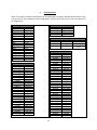
Assign pins to input and output signals. For this example, we will use SW1 for x2, SW0 for x1, and
LEDG(0) (green LED 0) for output f.
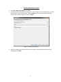
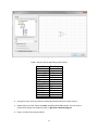
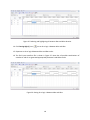
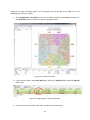
1. Select Assignments > Pin Planner. From the Pin Planner window, select View and make sure
that All Pins List option is checked as shown in the Figure below.
Figure 32. Pin Planner window.
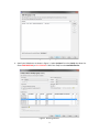
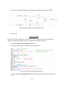
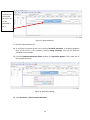
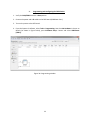
2. In the Location column, assign PIN_AE22 (green LED 0) to f, PIN_N25 (SW0) to x1, and PIN_N26
(SW1) to x2.
Figure 33. Assigning pins to inputs and output.
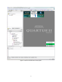
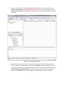
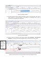
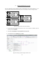
3. Close the Pin Planner window. Save and re-compile the Quartus project.
22