1
User Manual
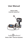
Model 1550
Field Setup Display
Series 1500™ Intercom Systems
1500 SYSTEM CALIBRATION
AND SETUP
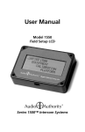
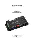
The Model 1550 is a liquid crystal display
that shows the setup menus and settings
for Series 1500 Intercom Systems. The
entire system can be calibrated from one
Counter Station (except for Model 1533*).
Connect the 1550 Field Setup Display to
the RJ45 jack on the underside of any live
Counter Station. (The jack is at an angle.)
Upon connection, the 1550 displays
“Series 1500 EQUIPMENT CALIBRATION
PLATFORM”.
SERIES
1
EQUIP 500
ME
CALIBRNT
AT
PLATF ION
ORM
CAT 5E/6
RECESSED
JACK
(ANGLED)
• Hold the SETUP key on the Counter
Station for one second to enter Setup
Mode. The 1550 displays the top level
of the menu shown on page 4. • To navigate the menus, use the
VOLUME UP and VOLUME DOWN
keys to move the cursor. 1500A COUNTER STATION (UNDERSIDE)
WARNINGS
•
•
•
•
•
•
•
Read these instructions before installing or using this product.
To reduce the risk of fire or electric shock, do not expose this unit to rain or moisture.
This product must be installed by qualified personnel.
Do not open the cover—there are no user-serviceable parts inside.
Do not expose this unit to excessive heat.
Install only in dry, indoor locations.
Clean the unit only with a dry or slightly dampened soft cloth.
LIABILITY STATEMENT
Every effort has been made to ensure that this product is free of defects. Audio
Authority cannot be held liable for the use of this hardware or any direct or indirect
consequential damages arising from its use. It is the responsibility of the user of the
hardware to check that it is suitable for his/her requirements and that it is installed
correctly. All rights are reserved. No parts of this manual may be reproduced or
transmitted by any form or means electronic or mechanical, including photocopying,
recording or by any information storage or retrieval system without the written consent
of the publisher.
Audio Authority reserves the right to revise any of its hardware and software following
its policy to modify and/or improve its products where necessary or desirable.
Audio Authority and the Double-A Symbol are registered trademarks of Audio Authority
Corp. Copyright June, 2007. All third party trademarks and copyrights are recognized.
2
• Use SETUP to enter a submenu or confirm a selection, and PRIVACY to go
back.
• Any changes you make are recorded as you exit each menu. When you exit
Setup Mode, you must choose to either save all changes and exit, or exit
without saving.
• If you need to re-enter Setup Mode, simply press SETUP for 1 second.
USING THE KEYPAD FOR NAVIGATION
CAMERA = Select next
or previous Station
(after selecting a single
Lane or Counter Station)
1
2
3
4
5
6
7
8
9 10 11 12
SETUP = Enter
or Confirm
13 14 15 16
VOLUME = Move menu
cursor up and down
PRIVACY = Go Back to
previous menu
POWER USER TIPS
• For faster menu navigation, submenus may be selected by touching the
key that is lit RED corresponding to the menu item (see the numbered keys
above). For instance, to enter BLOWER MOTOR DELAY, press 1 and then 1.
• To Exit Setup Mode from any menu, hold SETUP for one second and follow
the prompts on the 1550.
• After adjusting a Lane Station or Counter Station, use the CAMERA UP or
CAMERA DOWN keys to select other stations for adjustment without leaving
the submenu.
* Model 1533 Intercom / Telephone Interface requires separate programming
using the 1550. After setting up the intercom system, connect the 1550 to each
1533 in the system and perform setup tasks as outlined in the 1533 manual.
3
1500 SETUP MENU MAP WITH DEFAULT VALUES
Firmware Version 4.07 May 31, 2013
See 1533 manual for special telephone interface menu map.
Root Menu
First Menu Subset
1: System Parameters
1: Blower Motor Delay
2: Power Save Delay**
3: Supervisor Teller*
4: Lane Mirror Disable**
5: Traffic Sensor Tone
6: Background Threshold
7: Allow Video Scroll
8: Master Teller
2: Lane Parameters
1: Single Lane
2: Auto Select Lane
3: Group of Lanes
4: All Lanes
5: Cancel
1: Inbound Volume Level
2: Outbound Volume Level
3: Open Loop Gain
4: Handset Mic Level
5: Handset Speaker Level
6: Ringtone Override
7: Half Duplex Only
8: Program Audio Abate
9: Relay Operation
10: Swap Camera Up/Down
11: Suppress Video
3: Teller Parameters
1: This Teller
2: Single Teller
3: Group of Tellers
4: All Tellers
5: Cancel
1: Key Assignment
2: Allow Hands Free
4: Set Defaults
1: Cancel
2: Financial Defaults
3: Pharmacy Defaults
5: Memory Card
1: Cancel
2: Write To Memory Card
3: Read From Memory Card
4: Firmware Upgrade
6: Exit
1: Cancel
2: Exit and Save
3: Exit Without Saving
4
Second Menu Subset
Financial Default Value Pharmacy Default Value
3.0
90
None
Off
Use Lane Ringtone
4
On
None
3.0
90
None
Off
Use Lane Ringtone
4
Off
1
8
4
12
8
8
None
Off
Off
Selection Activates
Off
Off
8
4
12
8
8
None
Off
Off
Selection Activates
Off
Off
On
Off
*Not Available with 1-on-1 configurations
**Not available with 1509SD mini hub configurations
Note: See the 1533 manual for definitions and setup instructions.
5
DEFINITIONS
AUTO-SELECT 1 LANE
Allows installer to configure lane audio settings
using live audio from the lane. Useful for
adjusting inbound and outbound audio levels.
ALLOW HANDSFREE
Allow communication using speaker and
gooseneck microphone.
ALLOW VIDEO SCROLL
Inactive Counter Stations view all available
cameras in sequence; when video scroll is
disabled, inactive Counter Stations see only the
wideview camera (if installed).
BACKGRND THRESHOLD
Adjustment for level of background audio rejected
by Counter Station microphone.  0 = no rejection.
BLOWER MOTOR DELAY
If enabled, the period between disengagement of
blower and microphone audio un-mute.
FIRMWARE UPGRADE
This menu allows the firmware of system
components to be upgraded.
HANDSET MIC LVL
Inbound handset volume level adjustment.
HANDSET SPKR LVL
Outbound handset volume level adjustment.
HALF DUPLEX ONLY
Enables ‘push-to-talk’ operation.
INBOUND VOLUME LVL
Inbound volume level adjustment.
KEY ASSIGNMENT
This menu enables lane selection keys to be
redefined in any configuration desired. First
select the lane number to be assigned using
the VOLUME keys. Then touch the key to
be assigned to that lane. If the desired key is
already assigned, touch it twice. For 20 lane
systems use “Page Mode”. Page Mode allows
the user to flip between two “pages” of keys. The
first page contains lane 1-10, the second 11-20.
To enter or exit Page Mode, touch the HOLD key
while in KEY ASSIGNMENT.
LANE MIRROR DISABLE
OFF = idle Lane Stations display their own
camera output. ON = idle Lane Stations DO NOT display their
own camera output.
MASTER TELLER
Enables one Counter Station to monitor
conversations conducted on all other Counter
Stations.
OUTBOUND VOLUME LVL
Outbound volume level adjustment. 6
OPEN LOOP GAIN
Adjustment for adapting to different acoustic
environments. Lower this setting for Lane
Station acoustical environments with too much
microphone and speaker coupling. Increase
this setting to hear more of the customer while
operator is talking.
PGM AUDIO ABATE
ON = Program Audio heard ONLY when lane is
on hold. OFF = Program Audio heard when lane is idle
OR on hold.
PHARMACY SETTINGS
See the Model 1533 Telephone Intercom
Interface Manual for details.
POWER SAVE DELAY
If enabled, the length of time the system must
be idle before entering Power Save (LCD sleep).
This feature only applies to lane montiors, not
Counter Sation monitors.
READ FROM MEM. CARD
System settings are restored from hub memory
card.
RELAY OPERATION
Allows configuration of Lane Station relay
contacts (Model 1520 terminal block pos. 9 &
10). The contacts can be set to close using the
HOLD key, or while the lane is selected. (See
Operator Card l for HOLD key operation details.)
RINGTONE OVERRIDE
Press a key to select a unique ringtone for the
selected Lane Station(s). 1 = no override (plays the ringtone set by each
Counter Station). All other keys represent unique ring tones which
override any Counter Station settings.
SINGLE LANE
Allows installer to configure lane audio settings
without using live audio from the lane. Useful
when lanes are in use or audio is not required for
adjustments.
SUPERVISOR TELLER
If enabled, allows one Counter Station to monitor
others.
SWAP CAMERA UP/DOWN
Swaps functions of the camera up and down
buttons – use with third party camera tilt.
TRAFFIC SENSOR TONE
Press a key to select a unique ringtone for all
traffic sensor events.  0 = no ringtone, 1 = use Lane Station Ringtone
Override setting.
WRITE TO MEM. CARD
System settings are saved to hub memory card.
7
FIRMWARE UPGRADE INSTRUCTIONS
These instructions are applicable to Series 1500 Intercom systems with v4.0 or
higher firmware. If your system is not SD card-compatible, or has v3.9 or earlier
firmware, call Audio Authority technical support.
Download the latest firmware version from
http://www.audioauthority.com/page/series1500firmware and follow the
instructions to copy the necessary files onto an SD card.
Note: Series 1500 equipment with firmware prior to version 1.5 may not be
upgraded to version 4.07 using older hubs. To upgrade to version 4.07, these
systems must have a new 1509SD hub, or a new 1517SD hub card.
This upgrade may take several minutes. The system cannot be used during this
time, so plan for adequate down-time to complete and verify the upgrade.
• Insert the SD memory card into the 1509SD or 1517SD card slot.
• Connect a 1550 Installer Setup Tool to the underside of a Model 1500 Counter
Station that has firmware v4.0 or higher.
• Press Setup for 2 seconds
• Press Key 5 (1st button on second row)
• Press Key 4 (last button on top row)
• Press the Mirror key
• Press the Setup key twice
After a successful upgrade, “Firmware upgrade complete” is displayed on the
1550 screen. The menu on the 1550 now shows several new selection options
that apply only to the new 1500A, 1500AH, and 1533. Once the upgrade is
complete, all indicators on the hub will return to normal operation.
* 1-on-1 systems may be upgraded by temporarily connecting a hub.
2048 Mercer Road, Lexington, Kentucky 40511-1071
Phone: 859/233-4599 • Fax: 859/233-4510
Customer Toll-Free USA & Canada: 800/322-8346
Website: http://www.audioauthority.com
752-489 Rev 20130618