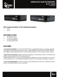
1
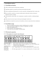
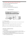
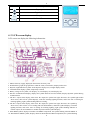
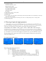
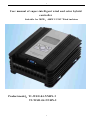
1
User manual of super-intelligent wind and solar hybrid
controller
Suitable for 300W, 400W 12/24V Wind turbines
Product model: T1-WSII-04-NNHN-2
T2-WSII-04-NNHN-2
1
2
Contents
1. Comprehensive introduction of products
1-1 Basic information -------------------------------------------------------------------3
1-2 Characteristics ----------------------------------------------------------------------3
2. Product parameters -----------------------------------------------------------------5
3. Installation and use
3-1 Installation attention ----------------------------------------------------------------6
3-2 Installation steps --------------------------------------------------------------------6
3-3 Electrical connection ----------------------------------------------------------------6
3-3-1 Description of external connection port ----------------------------------------6
3-3-2 Wiring attention --------------------------------------------------------------7
4. Parameters setting instructions
4-1
4-2
4-3
4-4
Key Function -----------------------------------------------------------------------8
LCD screen display -----------------------------------------------------------------8
Browsing of input and output parameters ---------------------------------------------9
Working para meters setting-----------------------------------------------------10
5. Special operations of controller
5-1
5-2
5-3
5-4
Manually unloading operation -------------------------------------------------------17
Controller warm reset start ----------------------------------------------------------17
Manual testing of PV input reverse ---------------------------------------------------17
Removing of abnormal information --------------------------------------------------17
6. Using of monitoring software
6-1 Brief description ---------------------------------------------------------------------19
6-2 Software and USB driver installation -------------------------------------------------19
6-2-1 Install the monitor software --------------------------------------------------19
6-2-2 Install the USB driver program -----------------------------------------------20
6-3 Using of software --------------------------------------------------------------------23
6-3-1 Browsing of software --------------------------------------------------------23
6-3-2 Connect the controller --------------------------------------------------------24
6-3-3 Read controller parameters ----------------------------------------------------24
6-3-4 Write controller parameters ---------------------------------------------------24
6-3-5 Backup of controller parameters -----------------------------------------------25
6-3-6 Read and write the parameter of backup files -----------------------------------25
6-3-7 Check controller dynamic parameters -------------------------------------------25
6-3-8 Debugging of controller software -----------------------------------------------26
6-3-9 Debugging of controller auxiliary functions -------------------------------------26
6-4 Description of monitoring software parameters
6-4-1 Description of parameters on page 1 -------------------------------------------28
6-4-2 Description of parameters on page 2 -------------------------------------------29
6-4-3 Description of parameters on page 3 -------------------------------------------30
7. Appendix: Definition of communication port ---------------------------------------32
8. Quality assurance and after-sales service --------------------------------------------33
2
3
1 . Comprehensive introduction of products
1-1 Basic information
Super- int ellig ent wind/ so lar hybr id cont roller is a new type of special high
performance control device for new energy application which is designed on the basis of ultra high
performance controller. It contains many years of application experience (such as waterproof,
dustproof, salt spray, wiring error, wind resistance limit control of Wind turbines, energy
management etc.), it has done to ultimate no matter it applied to the charging control or street light
control. In order to meet variety of applications, the controller adopts a hierarchical and modular
structure, all functions can be achieved with different functional plates according to actual
application, and it is convenient for rapid customization and application.
1-2 Characteristics
v Waterproof
Three defenses for circuit board, hierarchical design, even if small amount water enters, it will not
damage the device
v RS232 communication
Standard configuration RS232 communication, it is easy to do the monitoring with the computer
software. (RS485, short-range wireless is optional). Using a USB to RS232 members, more
convenient to exchange data with a computer (computer with USB interface can be used).
v Safety wire connecting
Terminals are treated with injection molding process, wiring short circuit and cross will not occur,
more safety for customers’ operating.
v Automatically alarming of battery reverse
Battery input terminal will not be damaged with continuous reverse, and it has buzzer alarm.
Avoid equipment damage and fire caused by wiring errors, and better protect the battery.
v Automatically alarming of Photovoltaic panels reverse
Photovoltaic panels will not be damaged with continuous reverse, and it has buzzer alarm. It will
not cause wiring errors especially when work at night. (Note: reverse connection detection in the
night needs manually keys intervention)
v Continuous short-circuit output protection
Discharge output terminal has cont inuous short-circuit protect ion, and over current
protect io n. It is reco vered after t he abnormal excluded. Avoid damage of t he
co ntro ller or fire caused by electrical equipment fault (especially t he short circuit).
v Patented Wind turbines steady speed generation control technology
Patented Wind turbines steady speed generation control method, which makes the Wind turbines
not run with super speed, the Wind turbines can keep generation with a limited set speed even in
the high winds, avoid direct stop of Wind turbines with over speed caused by strong wind. Greatly
improve the Wind turbines generation energy and keep the safe running of the Wind turbines.
v Patented Wind turbines stall current limit control technology
Patented Wind turbines stall current limit control methods, which makes Wind turbines not run
over current, avoid the damage of expensive generator caused by heating due to over current.
v Wind turbines input MPPT generation technology (boost)
Controller can provide automatically Wind turbines input maximum power tracking mode, or the
5 segments match curve input configuration mode(input rev to input current; or output voltage
to input current curve), which makes the high efficient generation of the Wind turbines, but with
low speed.
v Support multiple output mode selection
This co nt ro ller provides opt io nal mult iple output modes (light control, t ime co nt rol,
3
4
lig ht o n in t he morning, PWM dimming, reverse direct io n), which can sat isfy a
variet y o f applicat ions.
v Statistics the cumulative generating capacity, remaining power, speed, current, temperature
and other data
The controller screen displays not only the current, voltage, power of conventional Wind turbines,
PV, battery, and the output terminal; but also the cumulative generating capacity of Wind turbines
and PV, the remaining battery power, Wind turbines speed, unloading current, and the temperature
of controller.
v Alarm function when terminals up
When the terminals are up, the controller will alarm, which requires customers to use with the
correct install direction, avoid the possibility of damage caused by water comes into the controller
when used in the open air or due to bad weather.
2.Product Parameter
M odel
Battery parameters
Applied battery voltage
Battery protect method
Voltage at the over
voltage protection point
Voltage at the over voltage
recovery point
Voltage at the under voltage
protection point
Voltage at the under voltage
recovery point
Battery temperature compensation
Wind turbines input parameters
Rated power of applied Wind
turbines
Rated power of the terminal
Max. input current of the terminal
The default speed of the Wind
turbines generation with limited speed
The default current of the Wind
turbines generation with limited current
Wind turbines protection method
Unloading method
MPPT function
Input current of MPPT channel
PV input parameters
Rated input current of applied PV
Rated input current of terminal
Charging voltage drop
PV protection methods
Unloading method
Discharge the output port parameters
ou tput
T2-WSI I-04- NNH N-2
T1-WSI I-04- NNH N-2
24V
1 2V
Reverse connection protection (do not burn any components, with voice
prompt); over voltage protection, under voltage protection (for street light
and such kind of load)
2 9.0V±0.2 V
1 4.5V± 0.2 V
2 7.5V±0.2 V
1 3.7V± 0.2 V
2 1.0V±0.2 V
1 0.5V± 0.2 V
2 3.0V±0.2 V
1 1.5V± 0.2 V
5mv/℃/2V (settable) (optional component)
4 00 W/24 V
4 00 W/12 V
1 7 A d c (after rectification)
2 0 A d c (after rectification)
500 Rpm (settable)
25A
35A
1 7 A(settable)
2 5 A (settable)
over rev protection, over current protection, induction lightening protection
PWM stepless high-frequency soft unloading (built-in)
Boost MPPT model ( automatic tracking or 5 segments curve tracking)
12A
5 50 W/24 V( stand ard)
2 50 W/12 V( stand ard)
110 0 W/24 V( pti onal)
5 50 W/12 V( pti onal)
1 5 A( stan dard)
3 0 A( opti onal)
<0.2 V
Reverse connection protection (voice prompt)
Open circuit unloading
2 outputs
4
5
Current of each output
Output protection methods
Output control methods
Others
Auxiliary function
Display mode
Communication mode
Displayed parameters
Power consumption in standby
mode(screen backlight closed)
Operating mode
Working temperature / humidity
range (environment)
Protection grade
Controller size (L*W*H)
Net weight
12A
Over current protection (15A/30sec. 18A/0.4sec.), short-circuit protection
(current > 150A)
light control, time control, reverse output, PWM output (250HZ, only the 2nd
output has it)
Monitor of air temperature inside controller, temperature of unloading parts
and Wind turbines MPPT components, and also the monitor of control terminals
installed on the inversion (with voice prompt)
Liquid crystal (LCD) display
RS232(5V electrical level)/RS485 (standard)
Short-range wireless (optional)
Wind turbines input voltage/current/power/generated energy/rev/unloading
current
PV input voltage/current/power/generated energy
Battery voltage/charging current/power/total charging capacity/battery status
information
output current/power/abnormal information of the 2nd output port
About 20ma /24V system
3M foil key operation (4 keys)
-40~ +80℃ /20~8 5%RH( non condensing)
IP41
175 mm*1 48 mm *84 mm
1.8 KG
5
6
3. Installation and use
3-1 Installation attention
Please read this manual carefully before installation.
Installation should be operated by professional and technical personnel.
Before installation and maintenance, be sure the controller is uncharged and in the security state.
Please install the controller at a dry and ventilated place without dust, and avoid rainwater
infiltration and direct sunlight.
When install the cabinet inside, leave enough space around the controller or radiating through
box.
Keep away from corrosive gases and strong electromagnetic interference.
Installation area should be convenient for installation, electrical connection and later maintenance.
3-2 Installation steps
1.
2.
3.
4.
5.
Select the installation area (please read the ‘Installation notice’ carefully).
Check and clean the installation area, and leave enough space for wiring.
Prepare the installation tools.
Fix the controller at the installation place.
Check and be sure the controller is installed firmly.
3-3 Electrical connection
3-3-1 Description of external connection port
[SOLAR INPUT]-----Input terminal of solar panel, pay attention to the wiring polarity
[BAT INPUT ]------Input terminal of battery, which is applicable to the 24V level battery, pay
attention to the wiring polarity
[WIND INPUT ]-----AC input terminal of the Wind turbines, non-polarity input
[VO+ O1] --------The 1st output terminal. VO+ connects with load positive; O1 connects with
load negative
[VO+ O2 ] -------The 2nd output terminal. VO+ connects with load positive; O2 connects with
load negative
6
7
Attention: suggest doing wiring according to below order
1. First connect with output load (VO+ 01or VO+ 02)
2. Then connect with battery
3. And then connect with solar panel
4. At last connect with Wind turbines-driven generator
Connecting diagram
3-3-2 Wiring attention
Any incorrect operation during the wiring will cause danger, so the wiring operation must be
implemented by professionals.
Please choose the right size, and good insulation cables for electrical connection
Make sure the connectors are tighten during the wiring, no virtual connection
Avoid loose of connector caused by the shaking of wires during the movable use.
4 Parameters setting instructions
4-1 Key Function
The controller can cooperate with the system to work properly by setting the appropriate
parameters. Accordingly, the controller can monitor and display the set parameters, or dynamic input
and output data; it’s easy for debugging and maintenance.
The controller enters into the work standby status ([RUN] words flashing) as soon as it is
powered and initialized. The controller displays different information according to the different
function types, the specific kind to prevail.
There are 4 operation buttons on the panel
7
8
Butto n
Funct io n descript ion
Page up
Page down
Escape
Confirm / Enter
4-2 LCD screen display
LCD screen can display the following information:
1. Mains electricity supply, displayed when mains electricity exits
2. Wind turbines graph, the graph rotates when the rotate; when brakes, displays brakes box
3. Daytime, night indication symbol. In the daytime displays sun, at night displays moon.
4. Communication display symbol, temporarily retained
5. Battery voltage level symbol, 12V displays 12; 24V displays 24; 48V displays 48
6. Wireless communication display, displays the symbol when has wireless module, displays dynamic symbol during
communication
7. The No.1 output status display, when close the output, the symbol not light, otherwise, the symbol light. When
short circuit, short circuit symbol displays; when has morning lighting function, and in the state of waiting for
morning lighting, light symbol flashing indicates waiting.
8. The No.2 output status display, when close the output, the symbol not light, otherwise, the symbol light. When
short circuit, short circuit or over loading and such abnormalities, abnormal symbol displays; when has morning
lighting function, and in the state of waiting for morning lighting, light symbol flashing indicates waiting(for
normal output). If used LED driver module output, then LED symbol displays
9. Solar MPPT symbol, displays when has solar MPPT components, the symbol flashing when the MPPT works
10. Wind turbines MPPT symbol, displays when has Wind turbines MPPT components, the symbol flashing when the
8
9
MPPT works
11. PV parameter symbol
Wind turbines parameter symbol
Battery parameter symbol
LED drive output parameter symbol
No.1 output parameter symbol
No.2 output parameter symbol
Temperature symbol
Rev symbol
12. Digital display parameter / status symbol
13. Parameter setting symbol
14. Parameter unit
15. No. 1/2 output/ close status display symbol, displays when has output module, ON corresponding to output open
status, OFF to the close status
16. Battery status symbol, displays the rest battery power, after over voltage, displays the over voltage symbol
17. Data checking symbol
4-3 Browsing of input and output parameters
In the standby screen, press the [ENTER] button, the screen displays the word "WATCH", and
press [ENTER] again, first displays the words "PV", which means can check the PV input parameters,
in this state, press the page up or down buttons, can switch to other dynamic parameters,
corresponding to "PV", "WIND ", " BAT", "OUT1", "OUT2", "TMP", "REV." After selecting the
information need to be displayed, press [ENTER], you can enter the parameters class to be displayed
currently, each parameter class following several subproject parameters, they can be displayed through
up / down buttons. Any time after shows subprojects parameter class, press the [ENTER] can skip to
the next parameter class. Any time press [ESC] can exit the parameter display step by step until you
return to the standby screen.
For example (in the standby screen)
standby screen
press [ENTER]
press [ENTER]
press [ENTER]
Below shows all the displayed parameters:
PV------ PV input parameters
S-U-------- Solar input voltage (1 decimal point)
Unit: V
S-I--------- Solar input current (1 decimal point)
Unit: A
S-P--------- Solar input power (no decimal point)
Unit: W
S-d--------- Solar input generated energy (no decimal point)
Unit: Kwh
E-U-------- Analog voltage of external photosensitive resistor (1 decimal point)
Unit: V
(Use external photosensitive resistor to do day/night checking instead of PV
panel)
9
10
W IND----- Wind turbines input parameters
n-U-------- Wind turbines input voltage (DC voltage after rectification) (1 decimal point)
Unit: V
n-I--------- Wind turbines input current (DC current after rectification) (1 decimal point)
Unit: A
n-P-------- Wind turbines input power (DC power after rectification) (no decimal point)
Unit: W
n-d-------- Wind turbines input generated energy (DC generated energy after rectification)
(no decimal point)
Unit: Kwh
n-F--------- Wind turbines input unloading current (DC) (1 decimal point) Unit: A
n-C--------- Current of Wind turbines charging to battery (1 decimal point) Unit: A
BAT------- Battery charging parameters
b-U--------- Battery voltage (1 decimal point)
b-I---------- Total charging current to battery (1 decimal point)
b-P---------- Total charging power to battery (no decimal point)
b-d--------- Total charging capacity to battery (no decimal point)
OUT1----- The 1 st output para meters
O1I----------The 1 st output current (1 decimal point)
O1P----------The 1 s t output power (no decimal point)
O1T----------The 1 st output time ( no decimal point)
OUT2----- The 2 n d output para meters
O2I----------The 2 n d output current (1 decimal point)
O2P----------The 2 n d output powe r (no decimal point)
O2T----------The 2 n d output time ( no decimal point)
Unit: V
Unit: A
Unit: W
Unit: Kwh
Unit: A
Unit: W
Unit: Min
Unit: A
Unit: W
Unit: Min
TMP------- Controller internal temperature display
TNP------- Controller internal temperature ( no decimal point)
Unit: ℃
REV-------- Wind turbines rev parameter
NSP------ Wind turbines rev display ( no decimal point)
Unit: Rpm
4-4 Working parameters setting
The controller can set part of the key parameters through LCD screen. However, some advanced
parameters can be set by the extra USB monitoring communication data cable.
In standby state, press the [ENTER], then through the up/down buttons to select [SET], press the
[ENTER] again, the controller will be prompted for a password, enter the correct password and
press the [ENTER], then you can enter the menu. The default password is: 0000
The Key Operating Instructions:
Enter the menu password input interface, the bit flashes, and every time press Page
Down, flashing skip to the next operation bit; every time press Page Up, changes in
operating-bit data (+1). After you enter the correct password, you will be prompted to
"YES" and then enter into the menu parameter selection area. If wrong, prompts “ERR".
Through page up and down to select the current menu. In the current menu, press
"ENTER" to enter into the corresponding parameter setting interface immediately,
displays the actual setting of parameters. Modify the parameters as above describes, after
modifying the parameters, press the "OK" to save the parameter setting immediately,
prompt "ERR" if there is an error, no error prompts "YES". Any time, pressing "ESC" to
exit. Return to the previous level.
10
11
The controller can display all the setup parameters are as follows:
【 Add】【 OEY】【 SYS】【 t1O】【 t1F】【 t2O】【 t2F】【 ndS】
【 nUt】【 bEn】【 nbI】【 CLU】【 SrU】【 nnI】【 nnS】
【 OEY】 ----Enter the password configuration of parameter settings
Description: Through setting of this parameter, every time when you enter the menu to
set the parameters, you need to enter the correct password (same with this
parameter data) to perform menu operations, default value [000]
【 SYS】 ----Select 24V system / 12V system / 48V system or automatic recognition settings
Description: Select 24V system [000], controller works under the configuration of
24V level.
Select the 12V system [001], controller works under the configuration of 12V level
Select the 24V systems [002], controller works under the configuration of 48V level
Select automatic system [003], controller works under the configuration of
automatic voltage recognition.
Default: [000]
【 T1O】【 T1F】 ---These two parameters are combined for controlling the output: the 1st output
method.
Description:
【 T1O】 =0
【 T1F】 =0
range 0-16 hours
ΔOutput in the night: (through LCD screen, only this mode c an be set)
The 1st output is light control output mode: that means output after dark; closed after dawn.
ΔOutput in the day: (through USD data wire and software to set this mode)
The 1st output is light control output mode: that means output after dawn; closed after dark.
【 T1O】 >0
【 T1F】 =0
range 0-16 hours
ΔOutput in the night: (through LCD screen, only this mode c an be set)
The 1st output is time control output mode: output at night, closed when the set time
arrived. If the setting time has not arrived, but already in the daytime, output will be closed.
ΔOutput in the day: (through USD data wire and software to set this mode)
The 1st output is time control output mode: output in the day time, and closed when the
set time arrived. If the setting time has not arrived, but already in the night, close the
output in advance.
【 T1O】 =0
【 T1F】 >0
range 0-16 hours
ΔOutput in the night and output in the day are all valid
The 1st output maintains continuous output mode: that means maintain a continuous
11
12
output for 24 hours unless there is abnormality occurs (under voltage, over current, short
circuit, etc.)
【 T1O】 >0
【 T1F】 >0
range 0-16 hours
ΔOutput in the night: (through LCD screen, only this mode c an be set)
The1st output is morning lighting mode output: that means, after dark, output opens; close
output when last time reaches to [T10] setting time, and transfer to a waiting state, waiting
till to the [T1F] setting time, continue to open the output, until to the morning
ΔOutput in the day: (through USD data wire and software to set this mode)
The1st output is morning lighting mode output: that means, after dawn, output opens;
close output when last time reaches to [T10] setting time, and transfer to a waiting state,
waiting till to the [T1F] setting time, continue to open the output, until to the dark.
【 T2O】【 T2F】 ---These two parameters are combined for controlling the output: the 2nd output
method
【 T2O】 =0
【 T2F】 =0
range 0-16 hours
ΔOutput in the night: (through LCD screen, only this mode c an be set)
The 1st output is light control output mode: that means output after dark; closed after
dawn.
ΔOutput in the day: (through USD data wire and software to set this mode)
The 1st output is light control output mode: that means output after dawn; closed after
dark
【 T2O】 >0
【 T2F】 =0
range 0-16 hours
ΔOutput in the night: (through LCD screen, only this mode c an be set)
The 1st output is time control output mode: output at night, closed when the set time
arrived. If the setting time has not arrived, but already in the daytime, output will be
closed.
ΔOutput in the day: (through USD data wire and software to set this mode)
The 1st output is time control output mode: output in the day time, and closed when the
set time arrived. If the setting time has not arrived, but already in the night, close the
output in advance.
【 T2O】 =0
【 T2F】 >0
range 0-16 hours
ΔOutput in the night and output in the day are all valid
The 1st output maintains continuous output mode: that means maintain a continuous
output for 24 hours unless there is abnormality occurs (under voltage, over current, short
circuit, etc.)
【 T2O】 >0
【 T2F】 >0
range 0-16 hours
Δ Output in the night: (through LCD screen, only this mode c an be set)
12
13
The1st output is morning lighting mode output: that means, after dark, output opens; close
output when last time reaches to [T20] setting time, and transfer to a waiting state,
waiting till to the [T2F] setting time, continue to open the output, until to the morning
ΔOutput in the day: (through USD data wire and software to set this mode)
The1st output is morning lighting mode output: that means, after dawn, output opens;
close output when last time reaches to [T20] setting time, and transfer to a waiting state,
waiting till to the [T2F] setting time, continue to open the output, until to the dark.
ΔIn addition, the 2nd output can output PWM signal, does not rely on the [T2O] [T2F]
parameters, this function can be achieved through the mode set by software
through USB data wire.
When set to PWM output mode, it will output PWM signal
PWM signal frequency: 250HZ ±5HZ
PWM signal amplitude: Battery voltage
PWM output current: 12A(low level is valid)
This output mode mainly used for the LED lamp dimming, cooperate with our
energy management algorithm (need to use the monitoring software Settings) to
realize the output energy management, achieve more bright Light time.
【 NDS】 ------ Pole pair number set of the wind generator, used for measuring the Wind turbines
speed
Generally, wind generators are permanent magnet synchronous generator, how
many magnets inside; half is the number of pole pairs, for example, if there are 8
magnets, the number of pole pairs is 4.
Range: 2-100 default: 4 pairs
【 NUT】 -----Sustained braking time parameter set after Wind turbines braking,
After the Wind turbines brakes, Wind turbines can be released after the brake time
set by this parameter, and continue to generate electricity (except: after Wind turbines
brakes, if the brake current is too large, and do not reduce even last for some time, the
controller will release the braking action, and recheck brake conditions after a period
of time, if OK, re-brake, again and again, to avoid burn generator or controller due to
large current, limited current set by [NNI] parameters)
Range: 1-59
default: 20 minutes
【 BEN】 ----The buzzer sound enabled settings
13
14
When this parameter is set to [001], enable buzzer alarm
Following states will cause the buzzer ring:
1, A key input
2, The battery reversed
3, PV panels reversed
4, The temperature is too high
5, The 1st output is short circuit, over current
6, The 2nd output is short circuit, over current
7, The controller terminals is upward
【 NBI】 -------Wind turbines MPPT charging components maximum input current limit setting
1-In the automatic power tracking mode (only can be set by USB data wire)
This parameter is used to control the input current through the MPPT parts; and on the
other hand, control the matching of Wind turbines input impedance, if the value is set
too small, the MPPT algorithm is inefficient, but does not pin down the Wind
turbines; If it is set too large, the MPPT algorithm is high efficient, but may be drag
Wind turbines in low wind speed. So they need a reasonable set according to Wind
turbines power curve.
For example, in the low wind speed (such as 4.5 m/s), the Wind turbines can output
the maximum power under 2A current, and will not cause the stall run of Wind
turbines (pin down the Wind turbines, speed can not be improved), then this parameter
should be set to 2A, that is [NBI] = 20, there is a decimal point: 2.0A
Range 0-50 or 0-5A current. Specific depend on the maximum power configuration of
MPPT module.
2- 5In the 5 segments matching mode (only can be set by USB data wire)
Through USB data wire to set the 5 points Wind turbines curve of rev-current, or
voltage-current, the set current will be limited by the [NBI] parameter. As the controller
includes the main charging passage of the Wind turbines, MPPT low voltage charging passage,
so this parameter restricts the maximum input current of MPPT low voltage charging, can
avoid over current running of MPPT low voltage boost charging passage.
After set running in the curve matching, the controller will extract the input current from the
Wind turbines to charge the battery according to this charging curve. Generally, recommend
the experienced customers use this mode to match with the Wind turbines, to have the best
generating effect.
【 SrU】 -------Starting voltage setting of MPPT charging input carried out by Wind turbines
When the input voltage of Wind turbines is over this setting parameter, MPPT stat
charging, the controller does the maximum power tracking to Wind turbines input
automatically (o 5 segments curve matching)
14
15
【 CLU】 -------Input voltage setting corresponding to close the Wind turbines charging
When t he input voltage of Wind turbines is lower than setting parameter, close the
charging to MPPT, can avoid stopping of Wind turbines under a very low speed.
【 NNI】 ------ Wind turbines maximum input current setting
Wind turbines input current for generating exceeds the current set by this parameter,
will cause a controlled braking action, combining [NUT] parameter, and finish the
brake control.
Range 0-500, which is 0-50.0A default 18.0A
【 NNS】 ----- Wind turbines maximum rev limit setting
When the Wind turbines speed reaches the speed set by this parameter, the controller
controls the speed within this parameter setting value through unloading
automatically, stable the maximum speed, if the Wind turbines speed is too large,
exceeds the automatic steady speed range, continue for some time, will start braking,
braking time decided by [NUT].
Range 0-3000 rev / min
default 500
【 Add】 ----- Communication code of the controller
Give a code to different device during the multiple communications; every controller
code must be different with others, to avoid crosstalk.
Range 2 – 250 default 6
5. Special operations of controller
5-1 Manually unloading operation:
In standby mode (the controller displays ‘RUN’, and blinking), long press the [ESC] button
for 3 seconds, the Wind turbines will enter into manual brake status immediately, the Wind
turbines graphic symbol shows as a frame, and the Wind turbines is framed by it, which
means it’s braking now. If now you press [ESC] for 3 seconds, the braking action will be
released slowly, and the Wind turbines generates again.
5-2 Controller warm reset start:
Press page up and down buttons simultaneously for 3 seconds, LCD digital part displays
"RST", the controller is reset immediately, reinitialize working. The effect is the same as
remove the power and then energized. Recommend to perform this operation to reset
15
16
controller after setting all the parameters, or encounter problems.
5-3 Manual testing of PV input reverse (for wiring in the night)
When connect the solar panel in the night, this function is used to detecting whether there is a
reverse function (when wiring in the daytime, this function is failure)
In standby mode (the controller displays ‘RUN’, and blinking), long press the page up button
for 3 seconds, the controller displays ‘-C-’, continuously check if the solar panel is reversed.
If reverse is exists, displays ‘Err’, recheck after correcting, if OK, no error information will
appear.
5-4 Removing of abnormal information
Abnormal failure can be removed manually, and the method is: enter the menu, then exit,
and the failure is clear.
Buzzer installed inside the controller, different voices express different meanings
Operation
The controller is powered on
A key input (press the button)
The battery reversed
PV panels reversed
The controller terminals is upward
The internal temperature is too high(>95 ℃)
The 1st output is short circuit, over current
The 2nd output is short circuit, over current
Voice
One " Drip " sound
One " Drip " sound per pressing
Long “Drip” sound
Long “Drip” sound
Long “Drip” sound
Intermittent “Drip” sound
Intermittent “Drip” sound
Intermittent “Drip” sound
6. Using of monitoring software (optional function)
Only can be used after buying monitoring software and USB
communication data wire
6-1 Brief description
The controller can monitor and set parameters through LCD, and can also use computer
monitoring software provided by our company to set or check the data information. Use monitoring
software can provide more comprehensive regulatory measures.
Communications with computer contain TTL232 (standard configuration), 485 (optional),
short-range wireless communications (optional, external module), specifically based on the practical
application.
6-2 Software and USB driver installation
16
17
Supports WINDOWS XP/ WIN7/WIN8 WINDOWS VISTA systems
Below shows the process of using standard configuration interface (TTL232 interface)
6-2-1 Install the monitor software
Insert monitoring software CD enclosed with cable, run the Wind And Solar Hybrid Controller ().
exe program, complete the software installation according to the prompt.
After installation, below titles appeared on the desk
The left one is the driver program cabinet of USB data wire, right one is the shortcut of
monitoring software.
Decompress the left driver package into a folder; the default location is the installation directory.
After decompression, you can see the following files in the installation directory.
6-2-2 Install the USB driver program
1---Plug the cable into the computer's USB port
2---The computer will find hardware and prompt to install the driver
17
18
And then choose “install from a list or specific location”, click Next
Then tick “Search contains this position”.
Click the “Browse", select File ‘DRIVE’
Click Next:
Begin to install the driver. After
installation, the system will Re
hardware.
Then repeat the above operation.
Till now, driver installation finishes.
Your computer will get a COM port
You can right- click on the "My Computer” to check in the Device Manager
The USB Serial Port (COM4) is the COM port
18
19
Attention: if the COM port is larger than 15, it can be used after manually changing
of the port code (as the monitoring software only supports the code between
COM1-COM15)
Solut io n is:
Open identify device manager
according to above method,
Right-click the corresponding
COM port;
Select “property” in the menu
Pop up the right Property
window
Click “Port Setting”
And then click “Advanced...”
button
Pop up the modifying window,
as the right lower picture
Choose the COM port within 1-15
from the drop-down menu of “COM
Port Number”, then click “OK”
6-3 Using of software
6-3-1Browsing of software
After the above steps finished, the software can be used for monitoring.
Executed in the following order
1- Provide 24V (12V) power, makes the controller work
2- Plug data wire into the USB port of computer, another side plugged into the DB9 port of the
controller.
3-Open the monitoring software
19
20
Below interface displayed after opening the software
Click below interface can be switched to a different page
20
21
21
22
6-3-2 Connect the controller
Switch to the 3rd page, click auto configuration button, the monitoring software begins to
connecting with the controller, if the connects, data will be filled in the “communication port” and
“baud rate” automatically, finish the connection.
Once the connection is completed, the corresponding function is displayed, the associated function is
not displayed.
6-3-3 Read controller parameters
There are [read configuration] and [write configuration] buttons on page 1-3. After
connecting with the controller, the monitoring software can read the configuration of
controller through this [read configuration], if every page is read, all the parameters of the
controller will be displayed in the corresponding interface, which is easy for checking,
analyzing and modifying.
6-3-4 Write controller parameters
There are [read configuration] and [write configuration] buttons on page 1-3. After
connecting with the controller, write the parameters modified by monitoring software
into the controller through this [write configuration], if every page is written in, all
the parameters of the monitoring software will be record in the controller.
22
23
Attention:
1- Parameters are not lost after losing power
2-When the parameters are written in, some of them are valid immediately;
some of them will be valid after restart the controller. Recommend to
restart the controller after all the configuration is finished, to make all
the parameters be valid.
3-Recommend to read the internal parameters of the controller before
modifying the parameters, then modify on this basis, and write in at
last.
6-3-5 Backup of controller parameters
1- Please connect with controller before operation.
2-Before making the backup of controller parameters, first read the configuration on
page 1-3 through the [read configuration], and save them in the monitoring
software.
3-There is a button of [Backup parameter to file] on page 1, click this button, and select
file path and setting file name (the filename suffix is .max), then click confirm, a
parameter file is generated for later use.
6-3-6 Read and write the parameter of backup files
1- Please connect with controller before operation.
2-There is a button of [Read the backup parameter from file] on page 1, clicks this
button to select parameter file, if the parameter file is correct (the parameter file
matches with the hardware configuration of current controller. If the hardware
of controller is different, the reading maybe failed), there will be prompting of
successfully reading.
3-Write the parameters of 1-3 pages to the controller sequentially.
6-3-7 Check controller dynamic parameters
1- Please connect with controller before operation.
2-Switch to [Checking and debugging of parameters] on page 4, the parameters
will be updated once per second, for dynamic checking, and all the real-time
generation data of controller can be checked.
23
24
6-3-8 Debugging of controller software
1- Please connect with controller before operation.
2-Switch to [Checking and debugging of parameters] on page 4, then clicks
[Simulation testing interface] shows as below:
Do Analog output and closing operation to the 1st and 2nd output.
3-If the 2nd output is in the PWM output mode, there will be a debugging
interface on the page as below shows:
which is used to simulate the PWM signal output, then there has corresponding
PWM signal output at the output port.
6-3-9 Debugging of controller auxiliary functions
1- Please connect with controller before operation.
2-Click the button of [remove all the generated capacity record] on the extended
page of page 4, to remove all the generated capacity record, and recover the
generated capacity to 0
3-Click the button of [restart controller] on the extended page of page 4, to restart
the controller, the effect is the same as remove the power and then energized,
recommend to click this button setting of parameters is finished, to restart the
controller to make the parameters valid.
24
25
4-Click the button of [User Setup] on the extended page of page 4, to active the
controller code, describes the edition of information.
When the edition is finished, clicks [write configuration] to save it.
5-In multi- device monitoring status (if using RS485 communication), all
controllers are attached to one RS485 communication line. Search the device on
this line through clicking the [search] button on the lower left corner of page 4.
The searched device will be listed. When the searching is completed, click
[Save] button to save the device information, next time when you open the
software, all the device information will be displayed. Click on the
corresponding device, the monitoring, debugging, reading and writing data to
this device will be started.
6-4 Description of monitoring software parameters
6-4-1 Description of parameters on page 1
After connecting the controller, effective parameters are displayed; all of them are necessary
parameters. The qty of displayed parameters is more the set parameters on the LCD screen
comes with the controller. Part of correspondence between them as follows:
25
26
This page is used to set the configuration of Wind turbines MPPT 5 segments generation curve
A. Select Rev-Current modeIn this mode, 5 rev parameters and corresponding parameters
can be set, used to matching with Wind turbines input curve.
B. Select Voltage-Current mode In this mode, 5 voltage parameters and corresponding
parameters can be set, used to matching with Wind turbines input curve.
26
27
6-4-2 Description of parameters on page 2
In which
This parameter is applied for street light output
1.Use PV panels as brightness perception sensor (PV panel)
A.When the input voltage of solar panel is lower than the parameter value, starts output.
B.When the input voltage of solar panel is higher than the parameter value + 2.5V, closes
output.
2.Select photosensitive resistor as brightness perception sensor (photosensitive resistor)
A.When the input voltage of photosensitive resistor is lower than the parameter value, starts
output.
B.When the input voltage of photosensitive resistor is higher than the parameter value + 2.5V,
closes output.
initial value: 7.0V
27
28
6-4-3 Description of parameters on page 3
This page is used to set the battery charging parameters
(Parameters set for battery, which are suitable for lead-acid batteries, lithium batteries, etc.)
1、 Maximum limited voltage of battery. Default value 29.0V
When the battery voltage exceeds this parameter voltage, the controller sends a prompt
message, automatically close the input charging inside the controller, starts automatic
unloading program.
The maximum voltage of this parameter can be adjusted appropriately depends on
different capacities of the battery groups.
In 24V system, this parameter is equal to the controller internal parameter.
In 12V system, this parameter is equal to 2 times of the controller internal
parameter.
2、 Recovery voltage of battery’s over voltage. Default value 27.5V
When the over voltage occurs, and the battery voltage is lower than this parameter
voltage, the controller sends a prompt message, automatically start the input charging
inside the controller, closes automatic unloading program.
The maximum voltage of this parameter can be adjusted appropriately depends on
different capacities of the battery groups.
In 24V system, this parameter is equal to the controller internal parameter.
In 12V system, this parameter is equal to 2 times of the controller internal
parameter.
3、 Recovery voltage of battery’s under voltage. Default value 23.0V
When the under voltage occurs, and the battery voltage exceeds this parameter
voltage, the controller sends a prompt message, the driver recovers working, all
functions recovered.
The maximum voltage of this parameter can be adjusted appropriately depends on
28
29
different capacities of the battery groups.
In 24V system, this parameter is equal to the controller internal parameter.
In 12V system, this parameter is equal to 2 times of the controller internal
parameter.
4、 Lowest limit voltage of battery. Default value 21.0V
When the battery voltage exceeds this parameter voltage, the controller sends a
prompt message, closes all the output. Do charging under standby state.
The maximum voltage of this parameter can be adjusted appropriately depends on
different capacities of the battery groups.
In 24V system, this parameter is equal to the controller internal parameter.
In 12V system, this parameter is equal to 2 times of the controller internal
parameter.
ormally, the non-professionals please do not do any changes to the battery
parameters, otherwise, controller may not work properly, and may also cause
overcharge and over-discharge to the battery, damage the battery. Here is open to
customers, mainly for them who are familiar with the application and can configure
internal parameters of controller much more reasonable. Achieve longer service
time.
7. Appendix: definition of communication port
The controller is configured with a standard 9-pins connector port of DB9 for communication and
multi-function selection interfaces, which are defined as follows:
Definition of the pins:
1-- RXD pin (control the RXD pin) of 232 communication
TTL level
2 -- TXD pin (control the TXD pin) of 232 communication
TTL level
3 -- GND pin of 232 communications
4 -- TB pin of 485 communications
5 -- TA pin of 485 communications
6 -- External output power supply VCC, Voltage: 5Vdc, the maximum
current: 50mA
7 -- External output power supply V+, Voltage: battery voltage
8 -- External photosensitive probe (photosensitive resistor) terminal 1 (do
not rely on PV panel to detect the lighting)
9 -- External photosensitive probe (photosensitive resistor) terminal 2 (do
not rely on PV panel to detect the lighting)
Above function definitions relies on corresponding hardware, in the normal
communication, only pin1, 2, 3, 6 are available.
29
30
8. Quality assurance and after-sales service
One year warranty from the date of the products sold. Within the warranty period, the product
failures caused by normal use, our company will provide free repair or replacement. If the warranty
period has expired, our company still provides maintenance services, but requires a fee.
The product warranty is only available to the original purchaser, and it is not transferable.
Our company reserves the right to change products, product updates without notice.
n
n
n
n
One of the following conditions occurs within the warranty period, our company will not provide
free services:
Do not operate in accordance with the user manual, and caused damages.
Equipment damage caused irresistible natural disasters.
Customers reshape and modify the equipment.
Customer has signed, equipment damage caused by transportation.
30