1
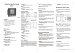
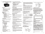
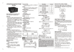
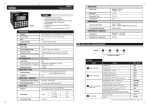
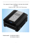
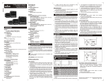
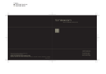
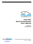
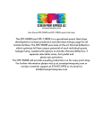
19. TEMPERATURE
Operating: 0 to 50°C
Storage : 0 to 75°C
6. TIME DELAY
0 to 9 seconds
20. HUMIDITY
Upto 95% RH ( Non-condensing)
7. RESET TIME
~1 sec.
21. WEIGHT
228 gms.
8. LED INDICATION
1. YELLOW: Power ON indication
2. RED(Full ON): Tripped indication
3. Three green LEDs(blinking): CBCT
error / CBCT absent
4. Three green LEDs showing leakage
Current condition (25%, 50% and 75%)
FEATURES :
℀ Monitors true RMS earth fault currents
(upto 30A)
℀ Sensitivity (ΔIn) & time delay (Δt)
adjustable
℀ LED indication for measured leakage
℀ ‘Test’ and ‘Reset’ functions
10. RESET ENABLE LEVEL
Below 85% of tripped level & in presence
of CBCT
11. MINIMUM TRIGGER TIME
125 msec.
13. POWER CONSUMPTION
3 VA
℀ CBCT Open circuit indication
℀ Two relay outputs : Protection relay and
Fail safe relay
SPECIFICATIONS
1. FUNCTION
Monitoring of earth fault currents in 3
or single systems
9. TEST/RESET FACILITY
1. Front panel
2. Remote (through terminal contact)
3. Reset on power interruption
12. CBCT RATIO
1200:1
current and various user settings
4 wire
2. SUPPLY VOLTAGE
230 VAC, 415 VAC (Separate model) (±15%)
AC:50 Hz/60 Hz
3. MONITORED LEAKAGE CURRENT
30mA to 30A with CT ratio 1200:1
4. SENSITIVITY (ΔIn)
30, 100, 300, 500mA & 1, 3, 5, 10, 20, 30Amp
DIMENSIONS (All dimensions in mm)
5. TRIP LEVEL LIMITS
95% to 105% of set value
All LEDs glows after set trip time is over
14. OUTPUT RATING
1. Trip Relay:
1 SPDT: NO(5A @ 250V AC)
NC(3A @ 250V AC) & Com.
2. Fail safe relay:
1 SPST: NO(10A @ 250V AC) & Com.
15. ACCURACY
± 5 % with respect to full scale
16. MEMORY
Storage of the leakage fault (fault clear by
pressing ‘Reset’ or on power interruption)
17. MOUNTING
Din Rail Mounting (size 35mm)
18. HOUSING
3M
73mm
45mm
68mm
OPERATING INSTRUCTIONS
ELR 600
SAFETY SUMMARY
52.5mm
90mm
All safety related codifications, symbols and
instructions that appear in this operating manual or on the
equipment must be strictly followed to ensure the safety of
the operating personnel as well as the instrument.
LED BARGRAPH
If the equipment is not handled in a manner specified
by the manufacturer it might impair the protection
provided by the equipment.
P
25 50 75 T
! CAUTION: Read complete instructions prior to
installation and operation of the unit.
WIRING GUIDELINES
%ΔI
CAUTION
Yellow
1. To prevent the risk of electric shock power supply to
the equipment must be kept OFF while doing the
wiring arrangement.
2. Wiring shall be done strictly according to the terminal
layout with shortest connections. Confirm that all
connections are correct.
Green
Red
NOTE FOR CONNECTION
For single phase applications, only the live and neutral
needs to be passed through the CBCT.
The Earth MUST NOT pass through the CBCT.
! CAUTION
The distance between relay and CBCT should be kept as
short as possible
1. To ensure the safe operation of unit, check the wiring
and connections.
2. It is recommended to test the unit periodically to
satisfy the regulations.
Use screen, shielded cable or twisted pair cable between
the unit & CBCT for long distance (Greater than 1m).
TERMINAL CONNECTIONS
18
17
COM
16
NO
Fail Safe Relay
2
1
15
NC
14
COM
13
12
11
10
7
8
9
NO
Trip relay
3
4
5
6
COM
230
L1
L2
L3
N
E
Document name: Operating / 0804 / ELR600 / Version 3 OP206-V03 Page 1 of 2
CORE BALANCED
CURRENT TRANSFORMER
MODES OF OPERATION
1) Turn power ON
2) The yellow “supply ON” LED will illuminate and all
other LEDs flash for a while.
DIA d
W
1. Test mode
The unit can be placed into a fault condition by
pressing the “Test” button on the front of the unit (or
by shorting terminals 7 & 9).
Key press
TEST
Display
P
25 50 75 T
Press
H
%Δi
Description
In test mode, all LEDs illuminate
& trip relay energises after set
trip time is over, indicating
proper operation of unit.
2. Normal Operating mode
Current range is set using knob of indication Δi (A)
Key press
Display
P
25 50 75 T
NONE
DIA D
%Δi
W1
B. For leakage current level > = 25% - LED ‘25’ glows
C. For leakage current level > = 50% - LED ‘25’ & ‘50’ both glow
Dimensions (mm)
D
d
H
W
W1
35
64
45
96
13
52.5
70
98
82
131
13
87
120
149
125
184
13
122
5-6
_
1.5 - 2
_
STD. TOL.
D. For leakage current level > = 75% - LED ‘25’, ‘50’ & ‘75’ glow
2-3
CT Type ZPC (Zero Phase Current)
When there is leakage current above the set value of
current unit trips ie all LEDs illuminate. At that time to
reset the unit to prior to the fault condition press reset
button.
Reset enable level
When leakage current increases above the set value
of current unit trips & all LEDs glows indicating trip of the
unit. At that time to reset the unit to previous condition (ie
prior to trip condition) ,leakage current should be
minimise to less than 85% of set value. This value is
known as reset enable value at which unit can reset.
Fail safe relay:
Fail safe relay ensures the proper working of unit at
the fault situation i.e. it doesn’t allow the fault occured in
the unit propagate ahead and gets de-energised to avoid
the damage due to over current.
Description
For eg. If Δi (A)= 10Amp &
Leakage current=2.5Amp then
LED ‘25’ (green) glows
A. For leakage current level < 25% - All bargraph LED’s off
CBCT
TYPE
Significance of the Reset button
E. For leakage current level 95 to 105% - All LEDs glow after set
trip time is over
Protection relay is energised & fail safe relay is de-energised
after set time delay is over.
NOTE: At CBCT error condition, red LED stays continuously ON
and other 3 green LEDs keep blinking.
Trip relay (Protection relay):
When leakage current exceeds the set value ,fail
safe relay de-energised & trip relay energised and doesn't
allow the further increment of leakage current by breaking
the power supply to the load. It is for protection of the unit
from over current so it is also called as a protection relay.
Trip time delay
The time taken by unit to trip when fault occures is
called trip time delay.
The time delay should be long enough to avoid nuisance
tripping caused by harmless transients, yet fast enough to
open the circuit when a hazard exists.
3. To reset the unit
Press the ‘Reset’ button on the front of the unit or
short terminals 8 & 9 to reset the unit
NOTE: 1. Applicable only when unit is in tripped condition &
leakage current is less than 85% of tripped level
2. The ‘Reset’ button does not work in the absence of
CBCT.
Key press
RESET
Display
P
25 50 75 T
Press
%Δi
Description
All LED’s are swtiched off
indicating output relay’s “non
tripped state”
USER GUIDE
Significance of the Test button
Test button is used to check the proper functioning of
the unit even in the absense of leakage current.
ie.To check the proper functioning of unit when there is no
leakage current & CBCT connected to unit press the test
button.On pressing test button, all LEDs glows after set
trip time is over showing that the unit is working properly.
NOTE: At CBCT error condition, red LED stays
continuously ON and other 3 green LEDs keep blinking.
(Specifications subject to change as development is a
continuous process).
Selec Controls Pvt. Ltd., India.
(Formerly Selectron Process Controls Pvt. Ltd.)
Tel: 91-22-28476443 / 28471882, Fax: 91-22-28471733,
Website: www.selecindia.com E- mail: [email protected]
Document name: Operating / 0804 / ELR600 / Version 3 OP206-V03 Page 2 of 2