1
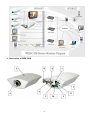
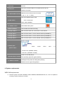
1. DC input DC 12V IEEE 802.3 Standard Ethernet 10/100M bps base port for 2. RJ45 port Network connection. DB9 PIN cord connects to the PC monitor 3-1.RS232 DB9 connector 2 : RX 3 : TX 5 : GND PIN1 ON: update program mode 3-2.DIP switch OFF: normal mode PIN2~4 NO CONNECT 3-3. RESET switch Reset WEB-CAM system 4.Built-in Camera CCD camera with manual focusing 5. Image output 1 BNC connector video out, for the built- in CCD camera 6. Image input 2 BNC connector video in, for the external camera (CHANNEL 2) 7. Image input 3 BNC connector video in, for the external camera (CHANNEL 3) 8. Image input 4 BNC connector video in, for the external camera (CHANNEL 4) 9. Alarm input Photo couple GPIO input 1,2 (Sensor input) Normal: N.O. (NORMAL OPEN) Active: N.C. (NORMAL CLOSE) Power on: left LED (red) lit 10.Power/status indicator CPU operating: right LED (green) flashing Sending/receiving data: left LED (yellow) flashing 11. Network indicator Network connect: right LED (green) lit 4. System requirements WEB-CAM requirements: Ethernet system, like ADSL MODEM, CABLE MODEM, BRIDGE/ROUTER, etc., which is capable of providing, fixed IP, floating IP or DHCP. 5