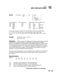
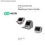
1
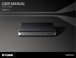
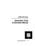
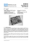
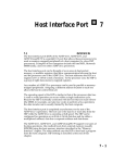
Engineer-To-Engineer Note
EE-19
Technical Notes on using Analog Devices’ DSP components and development tools
Phone: (800) ANALOG-D, FAX: (781) 461-3010, EMAIL: [email protected], FTP: ftp.analog.com, WEB: www.analog.com/dsp
Copyright 1999, Analog Devices, Inc. All rights reserved. Analog Devices assumes no responsibility for customer product design or the use or application of customers’ products
or for any infringements of patents or rights of others which may result from Analog Devices assistance. All trademarks and logos are property of their respective holders.
Information furnished by Analog Devices Applications and Development Tools Engineers is believed to be accurate and reliable, however no responsibility is assumed by Analog
Devices regarding the technical accuracy of the content provided in all Analog Devices’ Engineer-to-Engineer Notes.
Boot Paging II: Maximizing
Boot-Memory Efficiency on the
ADSP-21xx family DSP’s
(excluding the ADSP-218x)
Contributed by:
Last Modified:
Dan L.
10/20/97
Introduction
This document provides various strategies to
increase the efficiency and usefulness of standard
boot memory in 21xx systems (excluding the ADSP218x). The following topics are covered:
•
Maximizing the efficiency of boot-page allocation
within the boot memory of your ADSP-21xx
system.
•
Selecting the smallest boot memory device
possible for your ADSP-21xx system.
•
Creating multi-bank boot-page systems with 16
and 32 boot-pages.
•
Mapping program memory and data memory
into boot memory for large amounts of 8-bit
wide storage.
•
Modifying the boot memory image file.
•
Description of an example system using all of
the above concepts.
These methods can be complicated to implement,
yet can effectively streamline certain applications.
For more information on boot-pages, see section 10.4
of the ADSP-21xx Family User’s Manual, or the
following Analog Devices Engineers Note: Boot
Paging I: FAQ - Boot Pages on the 21xx Family
DSP’s (excluding 218x & CSP01), #XXX.
Boot Memory Overview
The Analog Devices ADSP-21xx family of Digital
Signal Processors (DSP) have a built-in booting
routine that loads 24-bit program memory (PM) into
internal RAM from an 8-bit boot memory device.
Booting can occur automatically when the DSP is
reset and/or while the DSP is running. Boot
memory is divided into eight pages. Each page holds
an entire memory image of the DSP’s internal PM.
When configured to load PM from boot memory at
reset, the DSP automatically loads boot-page 0.
Each 24-bit program memory word is stored in 4
bytes of boot memory. Therefore, the length of a
boot-page (in bytes) is always 4 times the number of
PM words stored within it.
This boot memory device is most commonly a ROM
of some sort but can be any memory device (FLASH
RAM, static RAM, or another processor) as long as
it is fast enough and compatible with the DSP’s
external memory interface.
Basic Boot Memory Interface
The standard method used to connect an ADSP21xx DSP to boot memory is to connect pins A0-A13
of the external DSP bus to pins A0-A13 of the boot
memory and pins D22 and D23 of the DSP to pins
A14 and A15 of the boot memory. Pins A0-A12 cycle
through the 8192 locations of each page. Pins A13,
D22 and D23 select the page. This interface
requires a minimum of 512 Kbits of boot memory.
The ADSP-21xx family DSPs built-in boot-page
loading hardware assumes that the boot pages will
be 8 Kbytes apart in boot memory. For example,
boot page 0 starts at boot memory address 0, boot
page 1 starts at boot memory address 0x2000(hex),
etc. If your system uses a DSP that has less than
2Kwords of program memory, there is unused
memory within each boot page in the boot memory.
For instance, the ADSP-2115 has only 512 words of
PM and requires 2 Kbytes of boot memory space per
boot page. This leaves 6 Kbytes of boot memory
unused per boot page. If the ADSP 2115 system
uses all eight boot pages with this addressing
scheme, the system requires 512 Kbits of boot
a
memory. This 512 Kbit boot memory has a
maximum of 2K x 8 = 16 Kbytes worth of boot data
and a minimum of 6K x 8 = 48 Kbytes of unused
data. Figure 2 shows a memory map of this
allocation scheme.
Removing Unused Memory
By rewiring the address lines from the DSP to the
boot memory, the unused memory (a minimum of
6K x 8 = 48 Kbytes) is removed.
A DSP with 512 bytes of PM such as the ADSP2105, 2115, 2163 and 2164, need only 2048 bytes to
be read from each boot page because the internal
PM is only 512 words long. By removing pins A11
and A12 from the boot memory and reconnecting
pins A13, D22, and D23 (boot-page select lines) on
the DSP to A11, A12 and A13 respectively, on the
boot memory, the 6Kbytes per boot page that was
previously unused is now eliminated and the pages
are packed next to each other. The result is 8 boot
pages stored in 128 Kbits of boot memory as opposed
to the original 512 Kbits.
In a system that uses a DSP with 1K of PM such as
the ADSP-2101, 2103, 2161, 2162 and 2111, each
boot page is 4096 bytes in length because the
internal PM is 1024 words long. Only pin A12 is
removed and pins A13, D22 and D23 move down one
address line. The result is 8 boot pages stored in 256
Kbits of boot memory verses the original 512 Kbits.
Table 1 summarizes these relationships. For more
information, see Section 5.4 in the ADSP-2100
Assembler Tools and Simulator Manual.
unused address line added as the most-significant
unused address line of the boot memory. These
unused lines can be tied to a memory mapped flipflop in a DSP system.
To load a boot page from another bank first write to
the flip-flop and specify the bank, then write to the
System Control Register (SYSCON) and write the
boot-page number. The unused bits may also be
connected to hard switches, or to an entirely
separate system. To connect these unused bits, the
actual boot memory image file(s) created by the
21xx splitter must be modified. See “Modifying the
Boot Memory Image file” section later in this
article.
Mapping PM or DM Space into Boot Memory
With a little logic between the ADSP-2115 and boot
memory, it is possible to map PM and/or DM into
unused portions of the boot memory. Although this
data is only 8-bits wide, it can store other data such
as function look-up tables and/or data constants.
To map PM and/or DM into unused portions of the
boot memory, both the boot memory select pin
(BMSL) and data or program memory select
(PMSL) pins must logically select different sections
of the boot memory.
In addition, the 14 address lines from the DSP must
connect directly to the 14 least significant address
lines of the boot memory. Less than 14 address lines
can be used to allocate a smaller block of PM or DM
but they should be contiguously connected on both
the DSP and boot memory. If no memory-efficient
allocation scheme is used this method is not
necessary (page packing). If this scheme is used,
additional logic is needed to allow BM, DM and PM
accesses to function correctly.
Total PM
in DSP
(words)
Min. Size
of BM
(Kbits)
Address
Lines Left
Disconnected
512
128
A11, A12
1024
256
A11
Modifying the Boot Memory Image file
2048
512
(none)
If you alter the configuration of the address lines
between the DSP and the boot memory, the ASCII
boot memory image file (*.bnm) created by the
splitter must also be modified to reflect these
changes. In many cases a simple text editor macro
can perform all of the required modifications. Below
are descriptions of the various boot memory image
file modifications required for the various schemes
described throughout this document.
Table 1 : DSP Boot Memory Sizes
Creating Multiple Boot-Page ‘Banks’
To create a system that uses more than 8 boot
pages, the boot memory must be an order of 2x
larger than the minimum size of boot memory as
defined in Table 1. A boot memory size of 2x yields
16 boot pages: 4x yields 32 boot pages. Every time
the boot memory is increased 2x, there is one
EN-19
Page 2
Technical Notes on using Analog Devices’ DSP components and development tools
Phone: (800) ANALOG-D, FAX: (781) 461-3010, FTP: ftp.analog.com, EMAIL: [email protected]
Removing address lines to ‘pack’ boot pages
next to each other:
The following switch must be used in the splitter’s
command line to set the ‘boot boundary’ between
pages.
•
For boot pages 4096 bytes apart (DSP’s with
1Kwords of program memory):
Original Data to be stored in memory mapped
program memory follows:
00, 01, 03, 04, 06, 07, 08, 0A, 0C, 0E…
The following data is put into Motorola-S format
starting at address 4800:
S1254800000103040607080A0C0E…
-bb 1024
•
For boot pages 2048 bytes apart (for DSP’s with
512 words of program memory):
-bb 512
(although this is not listed as an option for the
splitter, it will work)
Using Multiple Boot-Page ‘Banks’
To use Multiple Boot-Page ‘Banks’, each bank of
boot-pages is generated separately by the splitter.
Then the *.BNM generated by the splitter must be
edited manually (see Tables 2 and 3 for a
description of both Intel Hex and Motorola S data
formats). Using a text editor 1) load each .BNM file
and 2) patch them together. The address fields of
each .bnm file must be modified to reflect the new
location in boot memory (except for bank 0 which
always begins at zero).
Mapping Program and Data Memory into
Boot Memory Space
To place data into the data and program memory
mapped areas of boot memory, the .bnm file created
by the splitter must be edited manually with a text
editor. The following steps describe this procedure:
1.
Determine the boot memory address where the
data begins
2.
Create an addendum containing the data and
paste it onto the end of the .bnm file
3.
Save the original
The following is an example demonstrating this
process:
The original bnm file created by the splitter in
Motorola-S format:
S0030000FC
S125000018062034219A00FF…
S9030000FC
EN-19
Insert the following into the original bnm file:
S0030000FC
S125000018062034219A00FF…
S1254800000103040607080A0C0E…
S9030000FC
In this example system, PM is mapped to the boot
memory address 0x4800 (see Figure 1). A sequence
of 8-bit values located in this range must be
manually inserted into the .bnm file.
Describing An Example System
The example system described here uses an ADSP2115 with 512 bytes of PM, a 512 Kbit boot memory
device and a programmable logic device.
The system has 2 banks of 8 boot pages, each 2048
bytes long (since there is only 512 program memory
words to load) and 2 x 14K banks of 8-bit wide PM
(See Figure 1).
Because you need only 2048 bytes per boot page pins
A0-A10 of the DSP cycle through the 2048 locations
of each boot page. To select the boot pages, connect
pins A13,D22 and D23 of the DSP to pins A11-A13
of the boot memory (only while accessing boot
memory). This packs the boot pages next to each
other so they are all 2048 bytes apart (vs. 8192
bytes apart).
Pin A14 of the boot memory device is used to select
access of the boot pages or the 8-bit PM in boot
memory.
Pin A15 of the boot memory device can be set high
or low to yield two ‘banks’ of boot page and PM
blocks. In the example system, pin A15 is connected
to a memory-mapped D flip-flop located in data
memory space providing a total of 16 boot pages in
the system. To load a page from bank 1 into
memory (after page 0 has been loaded into PM) set
A15 to a logical high by writing to the memorymapped flip-flop and initiate the automated bootpage loading procedure.
Page 3
Technical Notes on using Analog Devices’ DSP components and development tools
Phone: (800) ANALOG-D, FAX: (781) 461-3010, FTP: ftp.analog.com, EMAIL: [email protected]
Below is a set of logic equations used in a
programmable logic device that is between the DSP
and the boot memory device:
Note: any signals with a ‘/’ in front are negated.
If an input or output signal has a ‘/’ in front, it is
negated when the signal enters or leaves the
programmable logic device)
inputs: A11, A12, A13
from the DSP
; address lines
Motorola S-Record File Format
The 8-bit Motorola S-Record File Format is a
printable ASCII format consisting of an optional
header record, and one or more data records
followed by an end of file record. Data records may
appear in any order. Values are represented as 2 or
4 hexadecimal digit values.
Field
Definition
S
Start of record mark (letter S).
/DMS, /PMS
DSP
; negated select lines from
N
Record type field–0 for header, 1 for data, 9 for
end of record. All other record types are ignored.
D22, D23
; data lines from the DSP
LL
Length field–Number of bytes to follow.
output: EA11, EA12, EA13, EA14 ; A11A14 of boot memory device
AAAA
Address field–Address of first byte.
DD
Data field
CC
Checksum field–One's complement of the length,
address and data fields modulo 256 - 1.
/ES
; boot memory select
equations:
EA11 = (A13 * BMS) + (A11 * PMS);
Table 3 Motorola S-Record Format :
EA12 = (D22 * BMS) + (A12 * PMS);
Example:
EA13 = (D23 * BMS) + (A13 * PMS);
S0030000FC
EA14 = BMS + /PMS;
S1090100010203040506E0
S9030000FC
Intel Hex File Format
The 8-bit Intel Hex File Format is a printable
ASCII format consisting of one or more data records
followed by an end of file record. Each record
consists of one line of information. Data records
may appear in any order. Address and data values
are represented as 2 or 4 hexadecimal digit values.
Field
Note: The first line in the above example Motorola
S-Record header record. The second line is a data
record addressed at location 100 with data values 1
to 6. The third line is the end of file record.
Definition
LL
Length field–Number of data bytes
AAAA
Address field–Address of first byte
RR
Record type field–00 for data and 01 for end
of record.
DD
Data field
CC
Checksum field–One's complement of
length, address, record type and data fields
modulo 256.
Table 2 Intel Hex Record Format :
Example:
:06010000010203040506E4
:00000001FF
EN-19
Page 4
Technical Notes on using Analog Devices’ DSP components and development tools
Phone: (800) ANALOG-D, FAX: (781) 461-3010, FTP: ftp.analog.com, EMAIL: [email protected]
Memory Maps For 2 ADSP 2115 Systems (512 words of program memory)
ROM
Address
DSP
Address
0x0000 Boot Page 0
0x0800 Boot Page 1
0x1000 Boot Page 2
0x0000
0x1000 Boot Page 3
0x2000 Boot Page 4
0x2800 Boot Page 5
0x6000
0x3000 Boot Page 6
0x3800 Boot Page 7
0x4000
0xC000
0x4800
0x8800
0x9000
0x9800
0xA000
Boot
Boot
Boot
Boot
Boot
Page
Page
Page
Page
Page
0
1
2
3
4
0x0000 Boot Page 0
0x0000
0x2000 Boot Page 1
0x2000
0x4000 Boot Page 2
0x4000
0x6000 Boot Page 3
0x6000
0x8000 Boot Page 4
0x8000
0xA000 Boot Page 5
0xA000
0xC000 Boot Page 6
0xC000
0xE000 Boot Page 7
0xE000
0xFFFF
0xFFFF
0x2000
0x4000
0x8000
0xA000
0xE000
0xFFFF
0x0000
0x0800
Bank
0
External
Program/
Data
Memory
0x8000
DSP
Address
ROM
Address
0x3FFF
0x0000
0x2000
0x4000
0x6000
0x8000
0xA800 Boot Page 5
0xB000 Boot Page 6
0xB800 Boot Page 7
0xA000
0xC000
0x4000
0xC800
0x4800
0xC000
0xE000
Bank
1
External
Program/
Data
Memory
Figure 1: Memory Map - Highly Excellent Boot-Memory
0xFFFF
0x3FFF
Interface
Mapped into BM
Mapped into BM
Mapped into PM & DM
Unused
Unused
Figure 2: Memory Map - Basic Boot Memory Interface with 2048
byte boot-pages
EN-19
Page 5
Technical Notes on using Analog Devices’ DSP components and development tools
Phone: (800) ANALOG-D, FAX: (781) 461-3010, FTP: ftp.analog.com, EMAIL: [email protected]