1
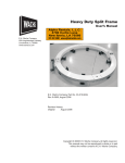
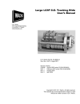
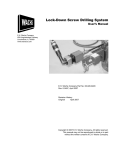
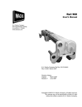
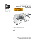
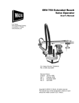
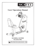
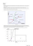
High Speed Handheld
Valve Operator
User’s Manual
E.H. Wachs
455 Comanche Circle
Harvard, IL 60033
www.wachsco.com
E.H. Wachs Part No. U10-010-MAN
Rev. 0-0310, March 2010
Revision History:
Original
March 2010
Copyright © 2010 E.H. Wachs. All rights reserved.
This manual may not be reproduced in whole or in part
without the written consent of E.H. Wachs.
High Speed Handheld Valve Operator
Part No. U10-010-MAN, Rev. 0-0310
E.H. Wachs
Table of Contents
Table of Contents
Chapter 1: About the High Speed Valve Operator . . . . . . . . . . . . . . . . . . . . . . . . . . . . . . . . . 1
Purpose of This Manual . . . . . . . . . . . . . . . . . . . . . . . . . . . . . . . . . . . . . . . . . . . . . . . . . . . . . . . . . 1
How to Use The Manual . . . . . . . . . . . . . . . . . . . . . . . . . . . . . . . . . . . . . . . . . . . . . . . . . . . . . . . . 1
Symbols and Warnings . . . . . . . . . . . . . . . . . . . . . . . . . . . . . . . . . . . . . . . . . . . . . . . . . . . . . . . . . 2
Manual Updates and Revision Tracking . . . . . . . . . . . . . . . . . . . . . . . . . . . . . . . . . . . . . . . . . . . . 2
Equipment Description . . . . . . . . . . . . . . . . . . . . . . . . . . . . . . . . . . . . . . . . . . . . . . . . . . . . . . . . . 2
System Specifications . . . . . . . . . . . . . . . . . . . . . . . . . . . . . . . . . . . . . . . . . . . . . . . . . . . . . . . 3
System Components . . . . . . . . . . . . . . . . . . . . . . . . . . . . . . . . . . . . . . . . . . . . . . . . . . . . . . . . 3
Motor Controls . . . . . . . . . . . . . . . . . . . . . . . . . . . . . . . . . . . . . . . . . . . . . . . . . . . . . . . . . . . . . 4
Direction of Rotation . . . . . . . . . . . . . . . . . . . . . . . . . . . . . . . . . . . . . . . . . . . . . . . . . . . . . . . . 5
Telescoping Valve Key . . . . . . . . . . . . . . . . . . . . . . . . . . . . . . . . . . . . . . . . . . . . . . . . . . . . . . 6
Chapter 2: Safety . . . . . . . . . . . . . . . . . . . . . . . . . . . . . . . . . . . . . . . . . . . . . . . . . . . . . . . . . . . . . 7
Operator Safety . . . . . . . . . . . . . . . . . . . . . . . . . . . . . . . . . . . . . . . . . . . . . . . . . . . . . . . . . . . . . . . 7
Safety Symbols . . . . . . . . . . . . . . . . . . . . . . . . . . . . . . . . . . . . . . . . . . . . . . . . . . . . . . . . . . . . 8
Protective Equipment Requirements . . . . . . . . . . . . . . . . . . . . . . . . . . . . . . . . . . . . . . . . . . . . 9
Chapter 3: Operating Instructions . . . . . . . . . . . . . . . . . . . . . . . . . . . . . . . . . . . . . . . . . . . . . . 11
Site Preparation . . . . . . . . . . . . . . . . . . . . . . . . . . . . . . . . . . . . . . . . . . . . . . . . . . . . . . . . . . . . . . 11
Set-Up . . . . . . . . . . . . . . . . . . . . . . . . . . . . . . . . . . . . . . . . . . . . . . . . . . . . . . . . . . . . . . . . . . . . . 11
Operation . . . . . . . . . . . . . . . . . . . . . . . . . . . . . . . . . . . . . . . . . . . . . . . . . . . . . . . . . . . . . . . . . . . 13
Operator Position . . . . . . . . . . . . . . . . . . . . . . . . . . . . . . . . . . . . . . . . . . . . . . . . . . . . . . . . . . 13
Turning the Valve . . . . . . . . . . . . . . . . . . . . . . . . . . . . . . . . . . . . . . . . . . . . . . . . . . . . . . . . . 13
Chapter 4: Maintenance . . . . . . . . . . . . . . . . . . . . . . . . . . . . . . . . . . . . . . . . . . . . . . . . . . . . . . 17
Lubrication . . . . . . . . . . . . . . . . . . . . . . . . . . . . . . . . . . . . . . . . . . . . . . . . . . . . . . . . . . . . . . . . . . 17
Repair . . . . . . . . . . . . . . . . . . . . . . . . . . . . . . . . . . . . . . . . . . . . . . . . . . . . . . . . . . . . . . . . . . . . . . 17
Replacing a Counter . . . . . . . . . . . . . . . . . . . . . . . . . . . . . . . . . . . . . . . . . . . . . . . . . . . . . . . . 18
Replacing the Sensors . . . . . . . . . . . . . . . . . . . . . . . . . . . . . . . . . . . . . . . . . . . . . . . . . . . . . . 19
Chapter 5: Parts Lists and Ordering . . . . . . . . . . . . . . . . . . . . . . . . . . . . . . . . . . . . . . . . . . . . 25
Drawings and Parts Lists . . . . . . . . . . . . . . . . . . . . . . . . . . . . . . . . . . . . . . . . . . . . . . . . . . . . . . . 25
Ordering Information . . . . . . . . . . . . . . . . . . . . . . . . . . . . . . . . . . . . . . . . . . . . . . . . . . . . . . . . . . 28
Ordering Replacement Parts . . . . . . . . . . . . . . . . . . . . . . . . . . . . . . . . . . . . . . . . . . . . . . . . . 28
Repair Information . . . . . . . . . . . . . . . . . . . . . . . . . . . . . . . . . . . . . . . . . . . . . . . . . . . . . . . . . 28
Warranty Information . . . . . . . . . . . . . . . . . . . . . . . . . . . . . . . . . . . . . . . . . . . . . . . . . . . . . . 28
Return Goods Address . . . . . . . . . . . . . . . . . . . . . . . . . . . . . . . . . . . . . . . . . . . . . . . . . . . . . . 28
E.H. Wachs
Part No. U10-010-MAN, Rev. 0-0310
i
High Speed Handheld Valve Operator
ii
Part No. U10-010-MAN, Rev. 0-0310
E.H. Wachs
Chapter 1, About the High Speed Valve Operator
Chapter 1
About the High Speed
Valve Operator
In This Chapter
PURPOSE OF THIS MANUAL
PURPOSE OF THIS MANUAL
HOW TO USE THE MANUAL
This manual explains how to operate and maintain the high
speed handheld valve operator. It includes instructions for
set-up, operation, and maintenance. It also contains parts
lists and diagrams to help you order replacement parts and
perform user-serviceable repairs.
SYMBOLS AND WARNINGS
MANUAL UPDATES AND
REVISION TRACKING
EQUIPMENT DESCRIPTION
HOW TO USE THE MANUAL
This manual is organized to help you quickly find the information you need. Each chapter describes a specific topic on
using or maintaining the equipment.
Throughout this manual, refer
to this column for warnings,
cautions, and notices with
supplementary information.
Each page is designed with two columns. This large column
on the inside of the page contains instructions and illustrations. Use these instructions to operate and maintain the
equipment.
The narrower column on the outside contains additional
information such as warnings, special notes, and definitions. Refer to it for safety notes and other information.
E.H. Wachs
Part No. U10-010-MAN, Rev. 0-0310
1
High Speed Handheld Valve Operator
SYMBOLS AND WARNINGS
The following symbols are used throughout this manual to
indicate special notes and warnings. They appear in the outside column of the page, next to the section they refer to.
Make sure you understand what each symbol means, and
follow all instructions for cautions and warnings.
This is the safety alert symbol. It is used
to alert you to potential personal injury
hazards. Obey all safety messages that
follow this symbol to avoid possible
injury or death.
NOTE
This symbol indicates a user notice.
Notices provide additional information to
supplement the instructions, or tips for
easier operation.
MANUAL UPDATES AND REVISION TRACKING
Occasionally, we will update manuals with improved operation or maintenance procedures, or with corrections if necessary. Revised manuals will be available for customers.
When a manual is revised, we will update the revision history on the title page and at the bottom of the pages.
You may have factory service or upgrades performed on the
equipment. If this service changes any technical data or
operation and maintenance procedures, we will include a
revised manual when we return the equipment to you.
EQUIPMENT DESCRIPTION
The high speed valve operator is designed to turn valves
from 6” to 60” at a higher speed than conventional valve
2
Part No. U10-010-MAN, Rev. 0-0310
E.H. Wachs
Chapter 1, About the High Speed Valve Operator: Equipment Description
exercisers. This is advantageous in situations where you
need to quickly open or close a valve, without needing to
run a high-torque exercising operation.
The machine operates on 110 VAC power and utilizes a
reversible motor to simplify valve excercising operations
and to reduce operator effort.
System Specifications
Application
Operates all gate valves 6” to 60” (152
mm to 1524 mm) and other equipment
requiring mechanized turning.
Maximum torque 350 lb-ft
Maximum speed 40 rpm
Power
110 V, 60 Hz AC; requires a 15 amp or
3500 W generator.
Rev. counters
Built in digital counter display with
1-revolution increments and push button
reset.
Valve key size
1” (2.54 cm) square solid
Socket
2” (5.1 cm) square, AWWA standard
Dimensions
Length: 40” (102 cm)
Width: 14” (36 cm)
Height: 3.5” (9 cm)
Weight
31 lb (14 kg)
Options
Telescoping valve key up to 8 ft. long;
2” square AWWA standard ductile iron
socket; stop collar; 15/16” drive socket
System Components
Figure 1-1 illustrate the components of the valve operator.
E.H. Wachs
Part No. U10-010-MAN, Rev. 0-0310
3
High Speed Handheld Valve Operator
Rotating head
Counter
Drive adapter
Electric drive
Figure 1-1. The photo illustrates the major components of the valve operator.
Motor Controls
Use the electric drive controls to set the speed, direction and
the gear ratio. The gear ratio switch has settings for high
range, low range, and neutral. The speed dial lets you vary
the speed within the current range while running the valve
operator.
Gear ratio switch
Speed dial
Use the speed control dial and the gear ratio switch to set
the electric drive speed.
4
Part No. U10-010-MAN, Rev. 0-0310
E.H. Wachs
Chapter 1, About the High Speed Valve Operator: Equipment Description
Low speed range
Neutral
High speed range
Position indicator
Figure 1-2. The gear ratio switch has positions for
low speed (turtle), neutral (0), and high speed
(rabbit). The switch is shown at low speed setting.
Direction of Rotation
The valve operator is reversible. Figure 1-3 shows the direction of rotation for the indicated motor direction. To reverse
direction, slide the motor direction switch to the opposite
position
Figure 1-3. The photo illustrates the direction of rotation for indicated motor direction.
E.H. Wachs
Part No. U10-010-MAN, Rev. 0-0310
5
High Speed Handheld Valve Operator
Telescoping Valve Key
A telescoping valve key allows you to reach valves at different depths, and to adjust the length of the key to position the
valve operator at the desired height. You can adjust the key
from 4 to 9 feet in length, and add an extension for a maximum of 12 feet. Figure 1-4 shows the valve key.
Valve operator shaft
Spring locking pin
Valve socket
Figure 1-4. The telescoping valve key can be extended
by pressing in the locking pin and pulling out the valve
socket shaft.
6
Part No. U10-010-MAN, Rev. 0-0310
E.H. Wachs
Chapter 2, Safety
Chapter 2
Safety
E.H. Wachs takes great pride in designing and manufacturing safe, high-quality products. We make user safety a top
priority in the design of all our products.
In This Chapter
OPERATOR SAFETY
Read this chapter carefully before operating the valve operator. It contains important safety instructions and recommendations.
OPERATOR SAFETY
Follow these guidelines for safe operation of the equipment.
•
•
•
•
READ THE OPERATING MANUAL. Make sure
you understand all setup and operating instructions
before you begin.
INSPECT MACHINE AND ACCESSORIES.
Before starting the machine, look for loose bolts or
nuts, leaking lubricant, rusted components, and any
other physical conditions that may affect operation.
Properly maintaining the machine can greatly decrease
the chances for injury.
ALWAYS READ PLACARDS AND LABELS. Make
sure all placards, labels, and stickers are clearly legible
and in good condition. You can purchase replacement
labels from E.H. Wachs.
KEEP CLEAR OF MOVING PARTS. Keep hands,
arms, and fingers clear of all rotating or moving parts.
E.H. Wachs
Part No. U10-010-MAN, Rev. 0-0310
Look for this symbol throughout the
manual. It indicates
a personal injury
hazard.
7
High Speed Handheld Valve Operator
•
•
Always turn machine off before doing any adjustments
or service.
SECURE LOOSE CLOTHING AND JEWELRY.
Secure or remove loose-fitting clothing and jewelry, and
securely bind long hair, to prevent them from getting
caught in moving parts of the machine.
KEEP WORK AREA CLEAR. Keep all clutter and
nonessential materials out of the work area. Only people
directly involved with the work being performed should
have access to the area.
Safety Symbols
This icon is displayed with any safety alert that indicates a
personal injury hazard.
WARNING
This safety alert indicates a potentially hazardous situation
that, if not avoided, could result in death or serious injury.
CAUTION
This safety alert, with the personal injury hazard symbol,
indicates a potentially hazardous situation that, if not
avoided, could result in minor or moderate injury.
NOTICE
This alert indicates a situation that, if not avoided, will
result in damage to the equipment.
8
Part No. U10-010-MAN, Rev. 0-0310
E.H. Wachs
Safety: Operator Safety
IMPORTANT
This alert indicates a situation that, if not avoided, may
result in damage to the equipment.
Protective Equipment Requirements
WARNING
Always wear impact resistant eye protection while operating or working near
this equipment.
For additional information on eye and face protection, refer
to Federal OSHA regulations, 29 Code of Federal Regulations, Section 1910.133., Eye and Face Protection and
American National Standards Institute, ANSI Z87.1, Occupational and Educational Eye and Face Protection. Z87.1 is
available from the American National Standards Institute,
Inc., 1430 Broadway, New York, NY 10018.
CAUTION
Personal hearing protection is recommended when operating or working near
this tool.
Hearing protectors are required in high noise areas, 85 dBA
or greater. The operation of other tools and equipment in the
area, reflective surfaces, process noises, and resonant structures can increase the noise level in the area. For additional
information on hearing protection, refer to Federal OSHA
regulations, 29 Code of Federal Regulations, Section
1910.95, Occupational Noise Exposure and ANSI S12.6
Hearing Protectors.
E.H. Wachs
Part No. U10-010-MAN, Rev. 0-0310
9
High Speed Handheld Valve Operator
10
Part No. U10-010-MAN, Rev. 0-0310
E.H. Wachs
Chapter 3, Operating Instructions
Chapter 3
Operating
Instructions
In This Chapter
SITE PREPARATION
SITE PREPARATION
SET-UP
Select the appropriate length valve key so that the top of the
key is at least waist-high when inserted on the valve nut. If
necessary, use the optional valve key extension.
OPERATION
Make sure you have a place to stand with sure footing for
both feet, and that you are not standing in water when plugging in or operating the machine.
Keep vehicles and any other equipment far enough away so
that the handle of the valve operator can rotate around the
valve key without obstruction.
SET-UP
1. Adjust the telescoping valve key to the appropriate
length by pushing in the locking pin and pulling out
the socket shaft. If necessary, add the extension to
lengthen the key.
E.H. Wachs
Part No. U10-010-MAN, Rev. 0-0310
The key should be
adjusted so that
the valve operator
is approximately
waist to chest high on the
user.
11
High Speed Handheld Valve Operator
Figure 3-1. Press in the locking pin to adjust the
length of the valve key.
2. Insert the valve key socket onto the drive nut on the
valve. Check that the top of the key is at the correct
height.
Figure 3-2. Put the socket onto the valve nut.
3. Place the valve operator on the valve key. Orient the
machine correctly for the direction you are turning the
valve. Slide the head of the machine down onto the
“shoulder” of the key shaft.
12
Part No. U10-010-MAN, Rev. 0-0310
E.H. Wachs
Chapter 3, Operating Instructions: Operation
Figure 3-3. The valve operator rests on the shoulder
at the top of the key shaft.
OPERATION
Operator Position
For safe operation, you should stand at the end of the
machine with the electric drive. Hold the handle of the
machine with one hand, and operate the electric drive
switch with the other hand.
The machine can be operated by two people. One operator
should stand at each end, out of the way of the handle’s
rotation.
WARNING:
The valve operator
can produce up to
350 lb-ft (475 N-m)
of torque. To avoid
possible injury, stand at the
end of the machine, instead
of beside it where the handle
can rotate into you.
Turning the Valve
1. Plug in the valve operator power cord.
2. Press the counter button to reset the counter to 0.
3. Set the speed dial to “A” (the slowest setting) to start.
E.H. Wachs
Part No. U10-010-MAN, Rev. 0-0310
NOTE: Start with
the gear ratio
switch in the low
range.
13
High Speed Handheld Valve Operator
Figure 3-4. Start with the speed dial set to the lowest
speed (“A”).
4. Engage the electric drive by squeezing the power
switch on the drive motor.
5. Run the valve operator for 2-3 revolutions to make
sure you are turning the valve in the free direction. If
you reach the end of travel, release the power switch
and reverse the motor direction.
6. When you have verified the valve direction, turn the
speed dial to set the desired speed.
Figure 3-5. Turn the speed dial to increase the speed.
7. To change between high and low gear ratios, release
the power switch and turn the gear ratio switch. A rabbit icon indicates high speed range; a turtle indicates
low speed range. The switch also has a neutral position (indicated by a 0).
14
Part No. U10-010-MAN, Rev. 0-0310
E.H. Wachs
Chapter 3, Operating Instructions: Operation
Figure 3-6. Turn the gear ratio switch to the speed
range desired.
8. If you are turning the valve to a specified position,
watch the revolution counter and stop when you have
reached the desired number of turns.
9. Turn the valve until you reach the desired position or
the end of travel. Release the power switch.
10. If you are logging valve information, write down the
direction and number of turns to reach the end of
travel.
11. To reverse the valve, reverse the motordirection and
repeat this procedure.
E.H. Wachs
Part No. U10-010-MAN, Rev. 0-0310
15
High Speed Handheld Valve Operator
16
Part No. U10-010-MAN, Rev. 0-0310
E.H. Wachs
Chapter 4, Maintenance
Chapter 4
Maintenance
In This Chapter
LUBRICATION
LUBRICATION
REPAIR
There is one grease fitting on the valve operator head.
Apply grease every few hours of operation.
Figure 4-1. Apply grease through the grease fitting
on the head.
REPAIR
The revolution counter display and sensors can be replaced
in the event they become damaged or stop working.
Before performing any service, make sure the valve operator is unplugged from the electrical source.
E.H. Wachs
Part No. U10-010-MAN, Rev. 0-0310
17
High Speed Handheld Valve Operator
Replacing the Counter
You do not need to remove the handle to replace the counter.
1. Remove the 2 screws holding the counter in the head.
Figure 4-2. Remove the 2 screws to take the counter
out of the head.
2. Pull the counter out gently. Pull the electrical connector off the back of the counter.
Figure 4-3. Pull the connector from the back of the
counter.
3. Plug the connector into the back of the new counter.
The connector can only be connected in one orientation.
18
Part No. U10-010-MAN, Rev. 0-0310
E.H. Wachs
Chapter 4, Maintenance: Repair
Figure 4-4. Plug the connector into the pin block on
the back of the counter.
4. Carefully tuck the wires back into the head and put the
new counter in.
5. Put in the 2 screws and tighten them snugly.
Replacing the Sensors
If the counter is working but is not incrementing as the
valve operator turns, the counter sensors may be malfunctioning. You will have to remove the handle from the head
to replace the sensors.
1. Remove the 8 screws that hold the handle to the head,
and remove the handle.
Figure 4-5. Remove the 8 screws holding the handle
to the head assembly.
E.H. Wachs
Part No. U10-010-MAN, Rev. 0-0310
19
High Speed Handheld Valve Operator
2. Remove and unplug the counter as described in the
previous section.
3. Place the head assembly on a suitable work surface
with the set screw holes on top. Loosen the two set
screws holding the sensors.
Figure 4-6. Loosen the 2 screws holding in the sensors.
4. Remove the sensors by pulling them out of the
machine shaft cavity. The wires, connector and sensors are a single assembly.
Sensors
Figure 4-7. Remove the sensors.
20
Part No. U10-010-MAN, Rev. 0-0310
E.H. Wachs
Chapter 4, Maintenance: Repair
5. Remove the set screws and verify clamping pads are
in place. These small rubber pads distribute the clamping force of the screw to prevent damage to the sensor.
Pads should stay in the set screw hole and block sight
of the sensor bore.
Figure 4-8. Verify pad placement, there is no need to
remove the clamping pads.
6. Identify sensor position. The sensor marked with a red
band senses rotation and must be placed in the proper
bore as indicated in Figures 4-10 & 4-11.
Connector
Red ID Band
Sensors
Figure 4-9. The sensors and wires to the counters are
a single assembly.
E.H. Wachs
Part No. U10-010-MAN, Rev. 0-0310
21
High Speed Handheld Valve Operator
7. Replace the new sensors into the holes to the cavity.
Ensure proper position of marked sensor.
Sensor with marked lead
Sensor with plain leads
Figure 4-10. Insert the two sensors into the holes
leading into the machine shaft cavity.
8. Slide sensors in until both contact the hub. Lightly
tighten set screws. Sensors must be able to move with
minimal force but not freely.
Sensor with marked lead
Sensor with plain leads
Machine shaft
Sleeve
Figure 4-11. Cross section of assembly showing sensors against magnet retaining sleeve.
9.
Rotate the drive hub two full revolutions.
10. Reconnect the counter and verify operation.
22
Part No. U10-010-MAN, Rev. 0-0310
E.H. Wachs
Chapter 4, Maintenance: Repair
11. Once proper operation is confirmed, tighten set
screws. Do not exceed 2 in*lbs or damage to the sensors may result.
Figure 4-12. Tighten the 2 set screws to secure the
sensors in place.
12. Install counter.
13. Re-attach the head to the handle.
E.H. Wachs
Part No. U10-010-MAN, Rev. 0-0310
23
High Speed Handheld Valve Operator
24
Part No. U10-010-MAN, Rev. 0-0310
E.H. Wachs
Chapter 5, Parts Lists and Ordering: Drawings and Parts Lists
Chapter 5
Parts Lists and
Ordering
DRAWINGS AND PARTS LISTS
The drawings and parts list on the following pages illustrate
the components of the valve operator assembly.
In This Chapter
DRAWINGS AND PARTS LISTS
ORDERING INFORMATION
E.H. Wachs
Part No. U10-010-MAN, Rev. 0-0310
25
26
COUPLER, DRIVE
RING, RETAINING
CLAMP, TOP HALF
SPACER, GEAR SET
GEAR, PLANETARY
GEARBOX, PLANETARY OUTPUT
RUBBER GRIP, HANDLE
BEARING, RADIAL
HOUSING, HIGH SPEED VALVE TURNER
BEARING, GEAR END
GEAR, PINION
66-148-00
66-144-00
16-076-00
16-077-00
11-030-00
56-202-00
56-203-00
11-103-00
11-054-00
U10-010-03
U10-010-01
U10-010-02
2
3
4
5
6
7
8
9
10
11
12
13
HOUSING, GEAR, MODIFIED
BEARING
RING, SNAP
HOUSING, REAR
COUNTER
SSSCP 8-32 X 1/2
GREASE FITTING, 1/4-28 UNF, STRAIGHT
SHCS 5/16-18 X 1.00
U10-010-05
56-040-00
56-039-00
16-075-00
63-007-00
63-026-00
90-024-02
90-500-05
15
16
17
18
19
20
21
22
23
Part No. U10-010-MAN, Rev. 0-0310
HX-SCHS #8-32 X 2.5
BHCS .375-16 X .75
FHCS #6-32 X .25
MOTOR ASSEMBLY
SENSOR ASSEMBLY
PAD, SENSOR CLAMPING
SLEEVE, MAGNET RETAINING
90-060-10
90-020-25
90-072-07
90-033-02
U10-010-20
U10-010-07
11-145-01
U10-010-11
24
25
26
27
28
29
30
31
MAGNET
DRIVE WELDMENT
56-009-00
U10-010-10
14
RING, RETAINING
BEARING
HANDLE
U10-010-06
1
DESCRIPTION
PART NUMBER
ITEM
0.75
2
1
1
2
3
7
12
1
2
1
1
1
1
1
1
1
1
1
1
1
2
1
1
1
2
1
1
1
1
1
QTY.
High Speed Handheld Valve Operator
Bill of materials for the high speed valve operator.
See facing page for identification of parts.
E.H. Wachs
10
26
E.H. Wachs
13
1
22
12
6
Part No. U10-010-MAN, Rev. 0-0310
29
15
21
30
24
31
14
18
11
17
27
20
4
16
24
7
9
8
19
24
25
E.H. WACHS UTILITY PRODUCTS PROJECT No.: U10-10
ASSEMBLY. NO: U10-10-00
PRODUCTION DATE: APRIL 2010
HIGH SPEED HAND HELD VALVE OPERATOR
5
3
2
10
28
Chapter 5, Parts Lists and Ordering: Drawings and Parts Lists
27
High Speed Handheld Valve Operator
ORDERING INFORMATION
To place an order, request service, or get more detailed
information on any E.H. Wachs products, call us at one of
the following numbers:
U.S Toll Free. 866-392-1060
US Local:
815-943-4785
Ordering Replacement Parts
When ordering parts, refer to the parts list in this chapter.
Please provide the part description and part number for all
parts you are ordering. Always note your machine model
number when ordering.
Repair Information
Please call us for an authorization number before returning
any equipment for repair or factory service. We will advise
you of shipping and handling. When you send the equipment, please include the following information:
• Your name/company name
• Your address
• Your phone number
• A brief description of the problem or work to be done.
Before we perform any repair, we will estimate the work
and inform you of the cost and time required to complete it.
Warranty Information
Enclosed with the manual is a warranty card. Please fill out
the registration card and return to E.H. Wachs. Retain the
owner’s registration record and warranty card for your
information.
Return Goods Address
Return equipment for repair to the following address.
E.H. Wachs
Utility Products Division
455 Comanche Circle
Harvard, Illinois 60033 USA
28
Part No. U10-010-MAN, Rev. 0-0310
E.H. Wachs
E.H. Wachs
455 Comanche Circle • Harvard, IL 60033
815-943-4785 • www.wachsco.com