1
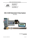
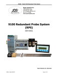
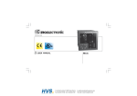
1500 VRF
USER’S MANUAL
Super Systems Inc.
7205 Edington Drive
Cincinnati, OH 45249
Ph : 513-772-0060, 800-666-4330
Fax: 513-772-9466
www.supersystems.com
Contents
Overview and Set Up .................................................................................................................................... 2
Spare Parts .................................................................................................................................................... 3
VRF Electrical Drawings and Plumbing Connections..................................................................................... 4
1
1500 VRF User’s Manual Rev -
Overview and Set Up
The 1500 VRF (P/N 13563) is a complete carbon control unit with a touch screen
operator interface.
There are three indicators on the front of the enclosure. When the unit is powered on,
the white light labeled “Control Power On” will be lit. During a burnoff, the green light
above the burnoff air flow meter will be lit. The red switch labeled “Process Alarm”
allows the operator to silence the unit if it is alarming.
For information on wiring the probe mV and probe thermocouple to the unit, please
reference the VRF 1500 electrical drawings in this manual.
Connect the ports on the side of the electrical enclosure to the probe using silicone
tubing. Connect tubing from the fitting on the side of the electrical enclosure marked
“Reference Air” to the “Ref. Air” port on the probe. A connection should also be made
between the “Burnoff Air” fitting and the “B.O.” fitting on the probe. Please see the
1500 VRF plumbing connections diagram within this manual. There is a barb fitting on
the stainless steel well on the heated probe. This is the vent, which needs to be routed
to an appropriately safe location.
The flow of the reference air and burnoff air can be adjusted using the corresponding
flow meters on the front of the unit.
For information on the touch screen operator interface, please reference the 9120 With
Touch Screen Interface User’s Manual. For information on the probe, please reference
the Gold Probe Instruction Manual.
2
1500 VRF User’s Manual Rev -
Spare Parts
The following is a list of spare parts recommended for the 1500 VRF.
P/N
Description
31125 Power Supply 24V DC
37120 Pump - Reference Air
37138 Valve, Solenoid, 3-Way
37177 Pump - Sample / Burnoff Air
13454 Series 9120 Controller
36013 Flowmeter, 0.2 to 2 SCFH
36028 Flowmeter, 2 to 20 SCFH
31604 SD Flash Card
13498 3.5" Color Touch Screen
3
1500 VRF User’s Manual Rev -
VRF Electrical Drawings and Plumbing Connections
VRF Electrical Drawing 1
4
1500 VRF User’s Manual Rev -
VRF Electrical Drawing 2
5
1500 VRF User’s Manual Rev -
VRF 1500 Plumbing Connections
6
1500 VRF User’s Manual Rev -
Revision History
Rev.
-
Description
Date
5-8-2012
Initial Release
7
1500 VRF User’s Manual Rev -
MCO #
2099