1
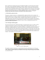
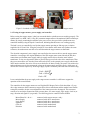
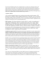
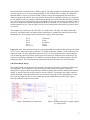
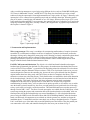
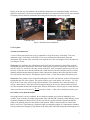
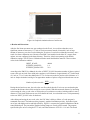
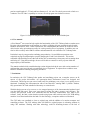
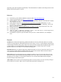
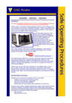
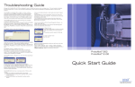
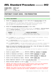
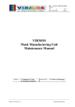
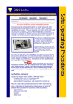
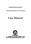
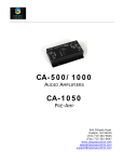
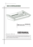
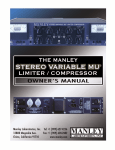
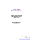
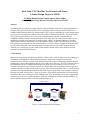
Real-Time, CNC Machine Tool Control with Linux:
A Senior Design Project at MUSE
Tie Duan, Ronnie Baroud, Daniel Amato, Albert LaRoe
School of Engineering, Mercer University, Macon, GA 31207
Abstract
As machine tools age and their existing controllers fail, the machine tools must be either modernized or
scrapped. This paper details the infusion of new technology and the resulting extended useful life of a
computer numerical controlled (CNC) tabletop lathe. This work was undertaken as a senior design project
by a group of senior engineers at Mercer University School of Engineering (MUSE). Key to the success
of the project was the ability to have a low cost, high performance real-time controller that was
compatible with the existing electrical components of the lathe. The CNC lathe was more that 15 years
old with no available replacement parts from the original vendor. The Enhanced Machine Controller
(EMC) Project software1 installed on a personal computer running a Linux Operating System2 was the
basis of the new controller design. The student authors were able to deliver a completely functional table
top CNC lathe along with a user manual to address operation and use of the EMC software in depth.
Artifacts were created using G-codes from existing models. Details of the project and the successful
conclusion are presented and discussed.
1. Introduction
Mercer University School of Engineering (MUSE) is filled with a variety of state-of-the-art technology to
aid students in fulfilling their educational requirements, ranging from a repertoire of electronic
components to the software available in the multiple labs to the variety of machining equipment present.
Unfortunately, some of that equipment has not received the care it deserved. The CNC Tabletop Lathe in
the Automation Lab was a sophisticated machine tool when it was first purchased. However, it was
rendered inoperable in 1992, when the X and Z axes failed. Since then, the lathe has been set aside and
virtually overlooked in order to make room for newer, more advanced machines. Later, it was dismantled,
and parts were scattered throughout different labs in the engineering building. Little attempt to repair the
lathe has been made over the past 15 years. As a result, a senior design student team of four has decided
to undertake the task of repairing the CNC Tabletop Lathe in the Automation Lab as well as upgrading it
so that a user can access a computer interface, which will communicate with the machines hardware, in
order to produce a part by means of G-code programming (Fig. 1).
Emergency Shut-Off
Input of Code
Execution of
Commands
Graphical
Interface
Progress of
Program
Figure 1. System interaction flow diagram
1
Figure 1 illustrates the end goal of the project and outlines the higher level interaction between entities.
The computer is fitted with Enhanced Machine Controller 2 (EMC2) software specifically designed to
take user input and manipulate any CNC machine in order to produce a desired part. The actions of the
machine are also recorded and fed back into the computer to inform the user of its progress. The computer
then relays this information to the user via EMC2’s graphical interface. The user at anytime may wish to
terminate/pause the program and can do so either through the software interface, or through the
emergency stop button on the front panel of the lathe if a safety hazard is present.
1.1. Deliverables, goals and criteria
The project’s end goal consisted of a working lathe with a computer interface and a user manual. All
malfunctioning parts were repaired or replaced. Functional safety features such as an emergency stop, and
safety covers were added. A computer interface compatible with the lathe and G-code usage was
implemented. Lastly, a user manual was created to instruct a student in basic operations of the interface
and lathe. Repairing this lathe is an excellent means for students of various specialties to demonstrate and
extend their engineering knowledge and ability to work as a team. An additional motivation was to
produce a functional education tool.
2. CNC Tabletop Lathe Description
This section describes the CNC Tabletop Lathe that was redesigned in this project. An outline of all key
components and controls is detailed. The CNC Tabletop Lathe revitalized in this work is a 4-axis
machine tool, originally equipped with a dedicated controller. It is important to note that some aspects of
the machine not updated such as some features of the electrical systems and technical specifications are
not covered in this paper. These details may be found in the reference3. As seen in Fig. 2, the outer casing
of the CNC Tabletop Lathe consists of several main components: Spindle, Spindle Speed Control, Safety
Cover, Emergency Stop, Spindle Motor, Stepper Motors4 (X and Z tool post directions), Headstock and
Tailstock. An overhead view is provided in Fig. 3.
Figure 2. 4-Axis CNC tabletop lathe
The spindle can rotate in a clockwise or counterclockwise direction as desired by the user. The green
‘Start’ button on the bottom left of Fig. 2 and the adjacent red ‘Stop’ button functions are also available
via the computer interface in addition to the hardware switch. Figure 4 depicts the stepper motor and side
view of the CNC lathe.
2
Figure 3. Overhead view of CNC lathe
Figure 4. Side view with stepper motor
2.1. Testing of stepper motors, power supply, and controller
Before testing the stepper motors, it has been reassured that the spindle motor was working properly. The
spindle motor is a 440W, 180V, 0.5hp, DC permanent magnet motor with maximum 5000 revolution per
minute. By simply connecting the machine to the power source, the speed of the spindle motor was
controlled manually using the Speed Control knob, indicating that this motor was working properly.
The lathe’s axes are controlled by two bipolar stepper motors operating at 200 steps per revolution
supplied with 2.9V and 3.8A. Using the principle of wires that the same motor coils produce the same
resistance, the student team was able to test and determine the stepper motors as functional.
The electrical components’ power supply was tested before the team was able to test the stepper motor
controllers. According to the original datasheet of the SD2 stepper motor control board, the SD drive
connections specified that motor supply and logic supply must be driven from the same isolated
transformer. A relay was bypassed in order to provide direct power feed to the drives transformer. Then
the power connections were checked: from wall outlet (120V) to the external power supply which sends
240V into the machine; the series of fuses were checked to be intact. Finally, the power was switched on
and a multimeter was used to measure the voltage at the motor supply and logic supply, which were AC
26Vrms and 18Vrms respectively. With logic supply equals 18Vrms the peak value was calculated using:
Peak = RMS 2
Peak = 18Vrms 2
Peak ≅ 25V
(1)
It was concluded that the power supply to the stepper motor controller is sufficient to support the
operation of the control boards.
The controllers for the stepper motors are two Digiplan SD2 Stepper Drives. Each board has a 32 way
drive edge connector which connects to stepper motor, drives transformer and the mother board. Before
testing the controller, the pin-out configuration of the connector needs to be mapped. This connector
consists of several major connections such as motor phase, 0V, motor supply, logic supply, clock in (or
step), direction and signal 0V (or ground). The following pins are connected in this fashion.
Motor Phase B+/- & A+/Motor Supply
Logic Supply
Signal 0V
Clock In
Direction
connected with
connected with
connected with
connected with
connected with
connected with
stepper motors x and y
drives transformer
drives transformer
drives transformer
motherboard
motherboard
3
The Clock In and Signal 0V pins of one controller board were connected to a function generator, and
output a square wave at 50Hz. The corresponding stepper motor began turning, thereby moving the
toolpost along the horizontal axis. The same process was repeated for the other stepper controller. Both
boards are proven to be operational. Additionally, both direction and clock-in pins of each controller
board has 12V charge of their own. This is a part of the reverse logic required to drive the stepper motors,
which will be explained further in Breakout Board Design (section 4).
3. Software Analysis
A PC was built with specific parts to carry out the necessary tasks in a timely manner. A PCI
parallel port was installed to enable communication between PC and Lathe. Linux was installed as
the primary operating system to run the EMC2 software. This software designed specifically for the CNC
lathe reduced the design time in half since there was no need to design new software. Applications of this
software have been an active area of research and discussion5.
EMC2 software: The Enhanced Machine Controller (EMC2) is capable of controlling up to 3
stepper motors simultaneously. However, the design involves only 2 axes, X and Z. The PC,
running Linux as its operating system, controls the stepper motor drives by sending signals
through the parallel port. These signals make the stepper drives move the stepper motors. There
are four main components to the EMC2 software: a motion controller, a discrete I/O controller, a
task executor which coordinates them and a collection of text-based or graphical user interfaces.
In addition there is a layer called HAL (Hardware Abstraction Layer) which allows simple
reconfiguration of EMC2 without the need of recompiling.
Graphical user interface (GUI): The graphical interface part of the EMC2 was used to interact with the
machine. The EMC2 comes with several types of user interfaces. The interface used to implement the
design is the Linux Based AXIS GUI. However, most consumers today operate windows as their primary
operating system. The goal is to get the machine up and running using Linux. The Linux based GUI is
written in python called AXIS. AXIS was the primary program used to control the machine graphically.
Before that the parallel port installed in the PC should be correctly interfaced with the stepper drivers.
G-code: G-code is a common name for the programming language used to control NC and CNC machine
tools. In a typical CNC program, G-code tells the machine tool what kind of action to perform, such as
rapid movement, axis movement, and tool bit feed rate. EMC2 was tested by programming G-code in a
text file and uploading the file. The GUI aspect of EMC2 allows the user to view a step by step design
process as the machine is building a particular part. Each part has different G-code. G-code could be
written by users for simple designs, but for more complex models, CAM software is recommended to
translate a DXF file produced by CAD software to G-code recognizable by EMC2.
Hardware Abstraction Layer (HAL): Hardware Abstraction Layer was used to configure EMC for
hardware devices and testing. The resistance encountered was the use of Linux. Mercer Engineering
students were mostly trained on assembly and high level computer programming languages such as Java,
C++, C, etc. The goal was to familiarize and train the student team with the software used to control the
Lathe.
There exists a text file that loads EMC2 saved in the EMC2 directory. By changing root privileges, the
team was able to have full privileges to edit the text file. Again, this was done through the HAL
Command line to access the folder with the EMC2 text files. Through the text file, the pins were
connected to the signals and ground. At first, problems were encountered while trying to move the file in
4
the command line to load up whenever EMC2 starts up. The major problem was finding the right location
of the pin out file to live, so it can start up with EMC2. After multiple lines of coding, an essential file
that loads EMC2 correctly was removed. EMC2 failed to start up and automatically shut itself down.
After locating the removed files, they were placed in the location to load EMC2 correctly. It was found to
be a lot simpler to make any changes with interfacing through the text file rather than the HAL Command
Line. The first step was connecting the pins to the signals. The text file was located where EMC2 loads up
the pin out configuration. Instead of going through the HAL command line, any changes necessary were
made through the text file. This also applies for any future functions that either needs to be added, edited
or removed.
The computer was connected to the CNC lathe via a parallel cable. The lathe was initially built with a
serial port. A breakout board was designed with a parallel port to establish the connection between the
lathe and the PC. It was mainly used to control the two stepper motor movements.
Pin 2
Pin 3
Pin 6
Pin 7
Pin 18-25
X direction
X step
Z direction
Z step
Ground
Logic level: After some internet research, it was determined that the standard 25 pin parallel ports operate
on TTL level is same as the stepper controllers. To further confirm this, channel 1 of an oscilloscope was
connected to pin 3 (X step) and ground, channel 2 to pin 7 (Z-step) and ground. Then a demo program
was run from the software and observed the square waves that were displayed on the oscilloscope. The
square waves both have amplitude of 5V, and their frequencies change as the demo program’s X and Z
coordinates change. This confirmed that the parallel port has the same logic level as the controllers.
4. Breakout Board Design
The breakout board was designed in order to achieve the highest performance, maximum reliability and
least complexity. It was designed to just control the two stepper motor movements. It employed
optocouplers to help cut down on ground loops and block voltage spikes, thereby making the board more
reliable. A sketch of the basic design concept is shown in Figure 5. According to the stepper controller
original data sheet, motor shaft will advance one step on the rising edge of a low-going pulse of at least
10us in the step input pin. However, the parallel port outputs signals that are positive logic. Figure 6
shows the difference in the two waveforms.
Figure 5. Breakout board connections
Figure 6. Parallel port signal vs. signal required
by stepper drivers
5
After several design attempts to reverse logics using different devices, such as CD4093BE NAND gates,
555 Timers in Monostable Circuits6, and SN74LS73 Flip-Flops, the team finally arrived at a simple
solution of using the optocoupler’s internal phototransistor as a logic switch. As Figure 7 illustrates, each
optocoupler is to be connected to one parallel port pin and one controller board pin. When the parallel
port pin is inactive, controller pin will maintain its own 12V charge. When a positive logic of 5V is sent
to the parallel port through EMC2’s step generator, the controller pin logic is pulled low to 0V and on the
rising edge of that low going pulse, one step is made by the stepper motor. A graphical representation of
this response is shown in Figure 8.
Figure 7. Optocoupler design
Figure 8. Graphical response of optocoupler design
5. Construction and Implementation
Wire-wrap prototype: Wire wrap is a technique for constructing small numbers of complex electronic
assemblies. It is an alternative technique to the use of small runs of printed circuit boards, and has the
advantage of being easily changed for prototyping work. Following previously concluded breakout board
design the student team was able to construct a prototype board for basic functionality tests. This
prototype performed as expected, it was able to allow software control of both stepper motors while
stepper controller boards emitted minimal amount of heat.
EAGLE CAD layout and fabrication: The objective is to build and install a durable and compact
breakout board permanently into the lathe. For this purpose, the student team downloaded the Freeware
version of EAGLE Layout Editor7, a powerful tool for designing printed circuit boards. First a breakout
board schematic using the Schematic Editor was drawn. Then, a set of pin heads for the screw post was
custom designed to connect to the controller pins, because the screw post collected from the discarded
original mother board was being used, and EAGLE does not have its footprint in the library. This
schematic was then sent to the board layout. The default borders were modified to the desired dimension
for the breakout board, 2 inch by 2.5 inch. Then, all components were laid onto the board with the best
routing possibility. This board was laid out with these important points in mind: organization,
components of the same axis are grouped close to each other, so it would be easy to perform
troubleshooting if needed; clarity, wires are placed as far apart as possible, so it would be easy to solder
once the board is printed; connectivity, the screw post and parallel port are positioned close to the edge,
so they can be easily accessed by required connectors. This finalized board layout was then processed
through CircuitCAM 5.1.6928. Text notes for each optocoupler were added onto the CAM layout, a final
text message stating the purpose and construction date of the breakout board was also added. After one
final inspection, this breakout board design was sent to BoardMaster 5.1.692 to begin the fabrication
process using the LPKF Laser & Electronics Photo Mat 542 PCB Milling Machine. After the breakout
board was fabricated, all components were soldered on with the greatest care, and then we began the
installation phase. To install this board, the team simply cut out the pre-designated area for “Computer
Link” on the back cover of the lathe, and secured the parallel port with a bracket. Then the parallel port
was connected to a PC cable, and controller board pins to the screw post as shown in Fig. 9.
6
Finally, as the last step of installation, all mechanical components were cleaned thoroughly, and oil was
applied to critical parts. All electrical components that have been removed for better access were returned
to original position, and then fitted under the housing and all necessary screws were applied.
External view
Internal view
Figure 9. Breakout board installations
5.1. Test plans
a) Linear movement tests9
A series of linear movement tests are to be conducted to verify the accuracy of the lathe. Tests were
conducted using G Code Entry on the EMC2. Tests were performed in both absolute, G90, and
incremental, G91, formats. They consisted of two separate tests. One was along the Z-axis, the other one
was along the X-axis.
Z-axis test: First perform a face-off operation on the end of the wax material, so the tool bit would be
flush against the end of the material. The tool bit needs to travel exactly one inch in the -Z direction. So,
enter G1 X0 Z-1 F1 into the G-code entry section of the GUI. Then use manual control to move the tool
bit in the -X direction to cut into the material just a small fraction of an inch. Back the tool bit out of the
material, and dismount the material from the chuck. Measure the distance the tool bit traveled from the
face off position to the final cut. This distance must be 1 inch +/-0.003 inch to satisfy this accuracy test.
X-axis test: First, perform a face-off operation along the side of the wax material, so the tool bit would be
flush against the side of the cylinder. The tool bit needs to cut 0.1 inch into the wax. So enter G1 X-0.1
Z0 F1 in the G-code entry section of the software interface. Then manually move the tool bit along –Z
axis for a short distance. After the tool bit has stopped cutting in the wax, use manual control to back it
out. Then dismount the material from the chuck, measure the diameter of the cut part, d, and the diameter
of the rest of the face-off section, D.
D−d
must be 0.1 inch +/- 0.001 inch to satisfy this accuracy test.
2
b) Creation of wax material artifact9
Once both accuracy tests are completed, then a complete program was written for machining a wax
cylinder. There is already an example program that came with the EMC2 package, called lathe.ngc. It has
a graphical simulation as shown in Fig. 10. One can first face-off the end of the cylinder, and find the
center of the material, then leave the tool bit at that position. EMC2’s manual control is used to home
both X- and Z-axis. Then lathe.ngc is loaded to begin executing this program. It is important to remember
to keep a hand on the Emergency Stop button on the front panel of the lathe during the machining process.
7
Figure 10. Graphical simulation shown of artifact test
6. Results and Discussions
After the first linear movement test was conducted on the Z-axis, it was obvious that there was a
significant amount of inaccuracy: 0.77 inch of Z-axis movement instead of intended 1 inch. A large
amount of inaccuracy was also revealed during the X-axis test. It was believed that this inaccuracy was a
result of software calibration error. Because when EMC2 was installed on the lathe PC, stepper motor
options were not configured in the home directory. Therefore, it has been operating under default
calibration settings. The GUI has a Calibration function under the Machine menu tab. There are three
values in the Calibration window:
INPUT_SCALE:
STEPGEN_MAXVEL:
STEPGEN_MAXACCEL:
4000.0
1.4
21.0
According to the EMC2 User Manual, the value of INPUT_SCALE determines number of pluses required
to move the axis one inch. Since 4000 pulses produce a travel distance of approximately 0.77 inch instead
of 1 inch, or 77% of 1 unit, then 4000 pulses is 77% of what was needed to produce a travel distance of 1
inch. A simple calculation would give an approximate number of pulses to begin a trial-and-error test run.
Number of pulses needed =
4000
≅ 5195
0.77
During the trial-and-error runs, the scale value was first edited, then the Z-axis test was conducted again
to measure the distance the tool bit traveled on a wax cylinder. With this measured distance, by increasing
or decreasing the value, a scale value of 5190 pulses per revolution was reached, which produced a travel
distance of 1.001 inch. With an error rate of less than 0.003 inch, it was decided to save 5190 permanently
as the new INPUT_SCALE value for both axes.
After editing and saving the new scale value, the CNC lathe’s ability to follow a G-code program’s
commands was tested. The lathe traced the program’s graphical simulation perfectly. It produced a part
out of wax with high precision and high efficiency. Figure 11 compares the graphical simulation with the
actual finished part. The part and the graphical cutting image are a nearly perfect match. The program
specified the piece to have a length of 1.57 inch, and a base diameter of 2*0.58 = 1.16 inch. The actual
8
part has a total length of 1.572 inch and base diameter of 1.161 inch. The whole process took a little over
2 minutes. The CNC lathe’s capability to execute a G-code program was declared a success.
Figure 11. Graphical comparison of simulation with the actual finished part
6.1. User manual
A User Manual10 was created to help explain the functionality of the CNC Tabletop Lathe to student users.
It begins with an introduction to the machine as a whole, explaining all parts, mechanical and electrical,
hardware and software, alike. It then explains how one can manipulate the controls as needed as well as
delve into the safety precautions necessary for such a powerful piece of equipment. In addition, one can
also be able to read up on the EMC2 software and understand its role within the CNC Tabletop Lathe.
It included a step-by-step procedure outlining part production. Several different operations were
explained varying from adjusting the speed to changing the X and Z-axis directions. This section
concluded with detailed processes that will aid the user in constructing various parts such as turning down
and facing off. Using this knowledge, the user will be able to construct a variety of parts within the
range/capacity of this machine.
The manual concluded with a troubleshooting section designed to help the users with various numbers of
problems that can occur with such a complicated piece of equipment. It explores how to address errors
and have information outlining emergency procedures.
7. Conclusions
In conclusion, the CNC Tabletop Lathe update and retrofitting project was a complete success on all
aspects of the project deliverables. An optocoupler-based interconnect board was designed and
constructed. This design was put onto a bread board for preliminary tests, where it was quickly proven
functional. Combining this interconnection with a Linux-based PC running EMC-2 yielded a modern,
fully operational CNC lathe suitable for laboratory or research work.
With this design proven to be a success, a wire wrapped prototype of the interconnection breakout board
was then built and tested. These tests were aimed at testing the lathe’s accuracy and efficiency. The
accuracy and precision results were established and the necessary modifications were made to the
software. Lastly, the final version board was made using layout editor software and a CNC PCB milling
machine. It was then installed into the lathe. For the final stage, a complete artifact was fabricated.
The CNC lathe was retrofitted to close to original state with the addition of a modern computer and
controlling software. The CNC tabletop lathe will fulfill its original purpose in educating students in
using CNC machines. Working with older technology could be frustrating because of the lack of
9
proprietary parts and component specifications. The determination of student senior design team was the
primary factor in the project’s success.
References
[1]
[2]
[3]
[4]
[5]
[6]
[7]
[8]
[9]
[10]
LinuxCNC.org, 2007, Enhanced Machine Controller –EMC, http://www.linuxcnc.org/
Ubuntu Linux Operating System http://www.ubuntu.com/
Denford Machine Tools Limited. Starturn Installation, Programming Instruction and Mainenance Manual,
West Yorkshire, UK. 1985.
Parker Hannilin Corporation. SD2, SD3, & SD5 Stepper Drives User Guide. Rohnan Park, CA. 1982.
Kommareddy, S. (2000) “PC-Based Open Architecture Servo Controller for CNC Machining,” The Second
Real Time Linux Workshop, Nov. 27-28.
Mims, Forrest M. III. Engineer's Mini-Notebook: 555 Timer IC Circuits. Siliconcepts Books, USA. 1984.
EAGLE PCB Layout Editor.
CircuitCAM 5.1.692.
Amato, D., LaRoe, A., Baroud, R., and Duan, T. (2007). “CNC Lathe Project,” Critical Design Review,
School of Engineering, Mercer University, Macon, GA.
Light Machines Corporation, SpectralLIGHT Lathe System User’s Guide, Manchester, New Hampshire,
1992.
Biography
Tie Duan: B.S.E in Electrical Engineering, graduated from Mercer University in December 2007. He is currently
working as a Design Engineer at Blue Bird Corporation in Fort Valley, GA. He is a Certified Break Technician from
Central Georgia Technical College (2003). His previous work experiences include: Electrical Engineer/Safety Intern,
Covidien, Macon, GA, and Trained Medical Interpreter, Medical Center of Central Georgia. He is a Student
Member of IEEE. He was on Dean’s List in Fall 2006 and Spring 2007.
Ronnie Baroud: B.S.E in Computer Engineering, graduated from Mercer University in December 2007. His recent
work experiences include: Math tutor and EBay Specialist. Other activities include: Macon Outreach Volunteer,
Varsity Basketball and Volleyball, and Division I Scocer Athlete.
Daniel Amato: B.S.E in Industrial Engineering, graduated from Mercer University in December 2007. His work
experiences include: GE Gas Turbines, EID Intern and Box Office Clerk. Other activities include: Member of Phi
Eta Sigma; He was on Dean’s List in Fall 2003 and 2006; He was in the International Baccalaureate Diploma
Program, and supervised intramural sports.
Albert LaRoe: Senior in B.S.E. Electrical Engineering, Mercer University, Macon, GA. He is currently working as
intern at Eglin Air Force Base. Other activities include: BCM, Bear Hands, and Eagle Scout.
10