1
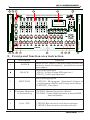
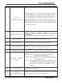
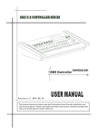
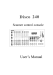
DMX 512 CONTROLLER SERIES
DMX Controller
CROCODILE 2024
USER MANUAL
This product manual contains important information about the safe installation and
use of this projector. Please read and follow these instructions carefully and keep this
manual in a safe place for future reference.
DMX 512 CONTROLLER SERIES
Table of contents
1
parameters
2
2
safety use cautions
2
3
contents in the package
3
4
Singal cable
3
5
DMX 512 address distribution
4
6
Signal cable link and scanner address setting
5
7
Operation panel view
5
8
Front panel function area instruction
6
9
D uplex key area
8
10
LCD display
9
11
Edit scanner chase
12
Running chases
10
13
Special scene presentation
11
14
How to set and cancel the joystick potentiometer
11
15
Conventional dimmer control
12
10
USER MANUAL
1/12
DMX 512 CONTROLLER SERIES
Thanks for using crocodile series scanner console! The console has
internationally standard DMX512 signal output. Before operation,
please refer to the use's manual carefully.
1 parameters
Output signal specifications
DMX 512/1990 internationally standard
Total number of channels
504 channels
Number of scanners
Max.number of channels for the
scanner
scanner
24 channels
Number of chases(scenes)
24 chase
Maximal number of chase
steps(scene)
20 steps
Total number of chase
steps(scene)
480 steps
Scene pause time
0.1-25.5 second/step
Scene cross speed
0-25.5 seconds
Dimmer channel
Display screen
DMX 512 outputs
interface
Memory capacity
channels
LCD display,16*2 characters
3-Pin XLR input/output
512K high capacity memory card
Input voltage
AC100-240V 50/60Hz 9V/1000mA
Volume
485mmX250mmX91mm
Weight
5 Kg
2. Safety use cautions
lThe console must be connected to the safety earth line.
lNever pulling out or inserting the communication cable with electricity.
lStart order please turn on all the controlled scanner power supplies first,and then
turn on the controller power,otherwise the controller is easy to be destoryed.
lprevent it from damp, water,dust,static, and maintain and clean it regularly.
USER MANUAL
2/12
DMX 512 CONTROLLER SERIES
3
l
l
l
Contents in the package
Crocodile series console
Crocodile series user's manual
Power adapter
1PC
1PC
1PC
4 Signal cable
l It use double-shield wire with the specified impedance of 120 ohms, and if
the cable exceeds 200 meters long or there are too many scanners a signal amplifier
should be added, and a terminal resistor should be added to the last scanner(120 ,1/4W).
l T he 1st pin of the signal cable is the grounding GND
2nd pin is negatives
and 3rd pin is positive signal; they should not be inversely connected and should not
be coldly welded.
l The signal cable should not be shielded by single-terminal earthing.
l The signal cable should not be wired together with strong electricity
USER MANUAL
3/12
DMX 512 CONTROLLER SERIES
5 DMX512 address distribution
C onsole uses 1 to 504 channels of dmx512
so it can control the scanners.
With no more than 24 channels. The address is distributed as follows
Scanner serial number
Scanner dmx starting address
Decimal system
Scanner address switch location
1
1
1 ON
2
25
1 ,4,5 ON
3
49
1 ,5,6 ON
4
73
1 ,4,7 ON
5
97
1 ,6,7 ON
6
121
145
1,4, 5,6,7 ON
1 ,4,6,8 ON
9
169
193
10
217
1,4,5,7,8 ON
11
241
1,5,6,7,8 ON
12
265
1,4,9 ON
13
289
1,6,9 ON
14
313
1,4,5,6,9 ON
15
337
1,5,7,9 ON
16
361
1,4,6,7,9 ON
17
385
1,8,9 ON
18
409
1,4,5,8,9 ON
19
433
457
1,5,6,8,9 ON
7
8
20
Dimmer channel 1-24
1 ,5,8 ON
1,7,8 ON
1,4,7,8,9 ON
481-504
USER MANUAL
4/12
DMX 512 CONTROLLER SERIES
6 Signal cable link and scanner DMX address setting
2#Scanner
DMX Address : 025
DMX 512 INTELLIGENT LIGHTING CONTROLLER
SINCE 2006
SINCE 2006
Ch1
Ch2
Ch3
Ch4
Ch5
Ch6
Ch7
Ch8
Ch9
Ch10
Ch11
Ch12
Ch13
Ch14
Ch15
Ch16
CH17
Ch18
Ch19
Ch20
Ch21
Ch22
Ch23
Ch24
0
10
10
10
10
10
10
8
8
8
8
8
8
6
6
6
6
6
6
4
4
4
4
4
4
2
2
2
2
2
2
0
0
0
0
0
0
2
4
6
8
EDIT
CYCLE
SUP
+
SET X / Y
P1
P2
P3
P4
P5
P6
P7
P8
P9
P10
P11
P12
P13
P14
P15
P16
P17
P18
P19
P20
P21
P22
P23
P24
SA
SB
SC
CROCODILE SERIES
CONTROLLER
DMX 512
LIGHT
-
DELETE
EDIT
7
12#Scanner
DMX Address : 265
DMX 512
CONTROLLER
1#Scanner
DMX Address : 001
Operation panel view
USER MANUAL
5/12
DMX 512 CONTROLLER SERIES
15
DMX 512 INTELLIGENT LIGHTING CONTROLLER
SINCE 2006
SINCE 2006
Ch1
Ch2
Ch3
Ch4
Ch5
Ch6
Ch7
Ch8
Ch9
Ch10
Ch11
Ch12
Ch13
Ch14
Ch15
Ch16
CH17
Ch18
Ch19
Ch20
Ch21
Ch22
Ch23
Ch24
0
10
10
10
10
10
10
8
8
8
8
8
8
6
6
6
6
6
6
4
4
4
4
4
4
2
2
2
2
2
2
0
0
0
0
0
0
2
4
6
8
EDIT
CYCLE
SUP
+
SET X / Y
P1
P2
P3
P4
P5
P6
P7
P8
P9
P10
P11
P12
P13
P14
P15
P16
P17
P18
P19
P20
P21
P22
P23
P24
SA
SB
CONTROLLER
DMX 512
LIGHT
-
DELETE
EDIT
SC
CROCODILE SERIES
5
4
8
13
14
DMX 512
CONTROLLER
3 2 1
6
8
7
9
10 11
12
Front panel function area instruction
Number
1
Description
POWER
BLACK
3
4
5
EDIT/RUN
Function
Switch ON/OFF console; if the power supply of whole unit
needs to be turned off completely please pull out external
power adaptor.
ON/OFF DMX signal output
* LED ON No light, all output DMX signals are 0
* LED OFF Normal signal output state.
Edit/running program
* LED ON Edit program. Maximum 24 chases of
each program editable and 20 steps each chases
* LED OFF Run chase.
Scanner dimmer * LED ON: Dimmer function be effected.
* LED OFF: Control lighting fixture as normal DMX
selection key
function channel
Cycle / SUP
* LED ON: Run selected several chases superpose
* LED OFF: Run selected several chases in cycle
USER MANUAL
6/12
DMX 512 CONTROLLER SERIES
6-7
P1-P24
Number key area
8
Duplex button area
* Edit program state - Select chase number and controlled
scanner number. Press number key one time to select
edit chase number and then press number key again to
select the number of scanner want to be controlled.
* Running program - Select chase number expect to run.
Work with function key to select scanner number and set
all 20 steps of 1st chase and first 4 steps of 2nd chase as
24 separately steps.
Please refer to instruction details of the duplex key
9
Page turning 1
LED ON: Slider area correspond to CH1-8
10
Page turning 2
LED ON: Slider area correspond to CH9-16
11
Page turning 3
LED ON: Slider area correspond to CH17-24
12
13
14
15
Joystick (Fine Key) Control X, Y of scanner or press it to fine adjust X,Y
SPEED CROSS
AUTO
LCD 16*2
* SPEED slider Change chase running time during
program or running period
* CROSS slider Adjust chase fade time during program
or running period
*AUTO: Set both speed & cross sliders at bottom means
run program in original time setting. (T he upper
part is used to change time manually accord
situation.)
Display relative data
Manual control selected lighting fixture DMX /dimmer
CH1-16
(channel Data slider area) channel value to active relative function
USER MANUAL
7/12
DMX 512 CONTROLLER SERIES
9
Duplex key area
[DELETE]
[
EDIT
area
[+
-]
]
[SET X/Y]
[CLEAR]
* Delete the chase or chase step during programming
elete the current chase step.
ressing 3 seconds to delete all steps of current.
[SET X/Y] - Press [DELETE] to cancel the X-Y channel
assignment.
View previous steps during programming
Save current chase steps or view next edited step during
programming
Active programming, press [SET X/Y] and select X/Y channel
between CH1-24 of scanner via SA/SB/SC to assign X/Y channel
to joystick. Press [SET X/Y] again to save and quit setting when
yellow indicate led ON.
* Press [CLEAR] to delete selected number key at once.
The number key can be selected repeat during program
running.
* In the running mode, all channel data will be cleared
to zero after pressing this key
* MODE1 All channel fade time be controlled by Cross slider during
program running
[CROSS MODE] * MODE2 The edited X /Y channel fade time be controlled by Cross slider
but all other channel run in jump way to prevent unedited colour
or gobos from playing during slow program running.
RUN
area
During chase running, Press [RUN SCENE] and P1-P24 to select first 24 steps
[RUN SCENE] of Chase 1 & 2 to run as special steps alone. Press [RUN SCENE] again to quite
this function and then current chase will continue to run.
[RELEASE
CHANNELS]
* Under MANUAL mode, Press [RELEASE CHANNELS] and move
sliders of selected channel by pressing SA/SB/SC or Joystick to change Ch1
-Ch24 output data during program running. Then current program will not
run as preset data but current data of selected channel. Press [RELEASE
CHANNELS] again to quit this function
* O indicates the CH1-24 channel data is controlled by manual slider,
and F indicates program run as preset data automatic..
[MANUAL]
During chase running, press [MANUAL] & any key of
(P1-P20) to select the scanner want to be controlled manually and then
move sliders of relative channel to control it manually. Then control
selected scanner in auto and manual at the same time.
USER MANUAL
8/12
DMX 512 CONTROLLER SERIES
10 LCD display
Display
XXXXXX XXXX
S/N:0020-02-2727****
TEST OK
RUN Chase[??]
[01][00.0][00.0]
RUN Chase[??]
CH[**
[***]
[***]
[***]
RUN SCENE
SELECT P1--P24
Specific information
Model and version number
Series Number and Test condition
[??] -- Input chase / step number
[01] -- Step number of chase
1st [00.0] -- Chase running time
Last [00.0] -- Chase cross speed
The upper line shows current running chase and
bottom line indicates current modified channel num
ber and channel data.
* Press P1 to P20 to select 20 steps of 1st chase
* Press P21-P24 to select 1st 4 steps of 2nd chase
EDIT Chase[??]
Step[01] [**]
Press [EDIT/RUN] and then corresponding indicate light ON
to enter EDIT situation.
[??] -- Edit chase number
STEP[01] -- Chase step number, modify it with [ -] or [+ ]
[**] -- current step is last step of edit chase. There will no
number if it has data already
EDIT Chase[??]
CH[**
[***]
or
[***]
[***]
The upper line shows current edit chase number ,
and the bottom line represents the modified channel
number and channel data.
EDIT Chase[??]
SPEE
[***]
or CROS
[***]
The upper line represents the chase number to be edited,
and bottom line indicates current modified chase running
speed or cross time
12345678
FFFFFFFF A
or FFFFFFFF B
or FFFFFFFF C
* Press [RELEASE CHANNELS] under MANUAL mode to get left menu.
* FFFFFFFF A -- Show 1-8 channel status
* FFFFFFFF B -- Show 9-16 channel status
* FFFFFFFFC -- Show 17-24 channel status
* O -- current channel under manual mode
F -- current channel under auto mode
* Press SA/SB/SC to select relative channel and move sliders of it to change status
USER MANUAL
9/12
DMX 512 CONTROLLER SERIES
Set X-Y
X [] Y
[]
MANUAL [??]
FFFFFFFF A
or FFFFFFFF B
or FFFFFFFF C
Press [EDIT] and [SET X/Y], select scanner by P1-P20 ( Set X/Y for all scanners
if not select scanner by P1-P20), press SA/SB/SC to select relative channel to
assign to joystick or press [DELETE] to delete previous assignment setting
* Press MANUAL during program running:
[??] -- Display current running Chase / Step
FFFFFFFF A -- Show 1-8 channel status
FFFFFFFF B -- Show 9-16 channel statu
FFFFFFFF C -- Show 17-24 channel statuss
O -- current channel under manual mode
F -- current channel under auto mode
* Select one scanner or several scanners via P1-P20
* Press SA/SB/SC to select relative channel and move sliders of it to change
status
11 Edit scanner chase
1
2
3
4
Press [BLACK] to turn off correspondent LED indicate light.
Press [EDIT/RUN] to turn on relative LED indicate light, and enter the program state.
Press any one of the number keys P1-P24 one time, to select edit chase number [ ].
Then press numbers (P1-P20 , to select controlled scanner and correspondent LED ON. If
correspondent indicate LED not ON, it means that scanner not be selected and Step 5 will
no effect with it.
5 Move sliders of CH1-8 to change value or press [SB/SC] to change CH9-24 value.
and slide (CH9-CH24) to call out the corresponding scanner effect(Control joystick to
change value If X/Y channel be assigned to joystick).
6 Repeat steps 4, and 5 to program other scanners to get expect effect
7 Move sliders of [SPEED] and [CROSS] set chase running speed and cross time.
8 Press[+ ] to save current chase/step and enter next step editing. Press[ -],can
view last chase or repeat above 4,5,6 and 7 steps to modify it and press[+ ] again to save it).
9 Repeat steps 4 to 8 to edit other chases/chase steps.
10 Press [EDIT/RUN] until relative indicate light off to quit program status and run program.
11 Repeat steps 2 to 10, to edit other chases.
12
Running chases
1 Press[EDIT/RUN] until indicate LED OFF.
2 Press number keys P1-P24 to select chase number and run it; if that chase number has
not been edited, then the corresponding LED will not ON.
3 Move sliders of [SPEED] and [CROSS] chase running speed and cross time. If [SPEED] or
[CROSS] slivers is at bottom AUTO area, then the chase will run as preset speed and cross
time.
USER MANUAL10/12
DMX 512 CONTROLLER SERIES
4 Press [CROSS MODE] to change the running mode -- refer to 9. Duplex key instruction.
5 If you want to run program in manual and automatic at the same time, please set as following steps.
1) Press [MANUAL] and [RELEASE CHANNELS] and then LCD display (12345678;
FFFFFFFFA).
2) P ress [SA / SB/SC] to check channel status. If channel show O, move slider of that channel to
release it and change status be F to make sure it under program control. (O -- Channel under
manual control; F -- Channel run as program preset data).
3) P ress [RELEASE CHANNELS] to save change and quit.
4) Press P1-P20 to select scanner to run in both manual and automatic mode -- several scanners
could be selected at the same time.
5) Press SA/SB/SC to select correspondent channel of selected scanner. Then this channel will
under manual control only to active manual and automatic modes at the same time (LCD
display O instead of F)
6 Press [BLACK] can make pause/play current chase -- correspondent LED light ON means pause
and OFF means play as normal.
13 Special scene presentation
In the state of chase running ( i. e., the indicating light of [RUN/EDIT] is OFF), Press
[RUN SCENE], then press any key of P1-P24 to select 20 steps of 1st chase and 1st 4
steps of 2nd chase. Therefore , we suggest to set first 24 steps with special effects.
14 How to set and cancel joystick
Joystick settings:
1) Press [RUN/EDIT] and relative indicate light ON to enter PROGRAM status.
2) Press [SET X/Y] and LCD display (set:X-Y X:[ ] Y:[ ])
3) Press P1-P20 to select scanner. (This step can be skipped if X/Y channel of all scanners is same)
4) Press SA/SB/SC to select correspondent X/Y channel to assign to joystick and then relative
yellow indicate led light ON or Press [DELETE] to cancel wrong setting and set correct channel..
5) Press [SET X/Y] again to save and quit.
Cancel joystick setting:
1) Press [SET X/Y ]
2) Press P1-P20 to select scanner. (This step can be skipped if X/Y channel of all scanners is same)
3) P ress [DELETE] to clear setting and correspondent yellow led light OFF.
4) press [SET X/Y] again to save change and quit.
USER MANUAL 11/12
DMX 512 CONTROLLER SERIES
15 Dimmer control
Distributed control In the status of non-programming, press SCAN/LIGHT and the
indicating light ON to enter dimmer function; Press SA/SB/SC to select relative dimmer
channel. Move sliders of it to change dimmer.
New features
1.Auto-save last running program when switch off or power off and
continue play last running program while switch ON or power ON again.
2.Play single chase or multi chases in cycle. The indicate led light of
CYCLE/SUP OFF means chase run in cycle.
3, Multi chases (maximum 8 chases) run at the same time. The indicate
led light of CYCLE/SUP ON means multi selected chases run at the
same time.
4, Set different X/Y channel of single scanner.
5, Under auto + manual mix running modes, release single channel or
all channel. Press [MANUAL] and [RELEASE CHANNELS], select
correspondent channel via SA/SB/SC to release it. LCD display will
show status of current channel from O to F. Press [CLEAR] and
release all channels. Then LCD display show status of all channel
from O to F.
Press [RELEASE CHANNELS] again to save and quit.
USER MANUAL 12/12