1
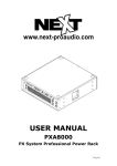
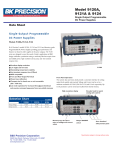
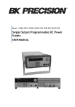
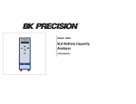
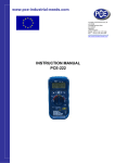
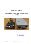
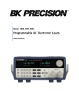
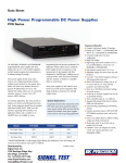
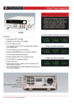
Data Sheet
Programmable DC Electronic Load
8600 Series
The 8600 Series programmable DC electronic
loads provide the performance of modular system
DC electronic loads in a compact benchtop form
factor. With fast transient operation speeds and
high 16-bit measurement resolution, these
standalone DC loads can be used for testing and
evaluating a variety of DC sources such as DC
power supplies, DC-DC converters, batteries,
battery chargers, and photovoltaic arrays.
The DC loads can operate in constant current
(CC), constant voltage (CV), constant resistance
(CR), or constant power (CW) mode and be
configured to provide a dynamically changing
load to the DC source with fast load switching
times. Versatile internal, external, and remote
triggering options allow the dynamic load
behavior to be synchronized with other events.
8600
Features
To ensure the reliability of your testing, the 8600
Series provides a power-on system self-test and
numerous protection features: overtemperature
(OTP), overvoltage (OVP), overcurrent (OCP),
overpower (OPP), and local/remote reverse
voltage (LRV/RRV) protection.
■
Transient mode up to 25 kHz in CC mode
■
List mode function
■
Store and recall up to 100 setups
■
Adjustable slew rate in CC mode
■
Flexible triggering options via front panel,
■
Voltage range up to 500 V
■
Current range up to 60 A
■
CC/CV/CR/CW operating modes
■
16-bit voltage and current measurement
system providing 1 mV / 0.1 mA resolution
external input, timer, or bus
■
Special Applications
The 8600 Series provides a built-in battery test
mode to measure the ampere-hour (Ah)
characteristic of a battery and a unique CR-LED
mode to simulate the loading behavior of a
typical LED.
Increase productivity by saving your test
parameters into any one of the 100 memory
Model
areas for quick system recall. All load parameters
such as voltage, current, slew rate, and width
can be set via the front panel or programmed
remotely. The 8600 Series provides standard
USB (USBTMC-compliant), GPIB, or RS-232
serial interfaces for remote communication.
8601
8602
Power
150 W
250 W
200 W
Operating Voltage
0 – 120 V
0 – 120 V
0 – 500 V
Rated Current
0 – 30 A
0 – 60 A
0 – 15 A
Built-in battery test function with voltage level,
capacity level, and timer stop conditions
■
Test modes to validate the OCP/OPP
protection functions of a power supply
■
CR-LED mode to simulate the loading behavior
of typical LEDs
■
Remote sense
■
Analog current control and monitoring
■
Thermostatically controlled fan
■
Standard USB (USBTMC-compliant), RS232,
and GPIB interfaces supporting SCPI
commands for remote control
■
OVP/OCP/OPP/OTP including local and
remote reverse voltage (LRV/RRV) protection
■
Compact 19” half-rack form factor allows for
side-by-side rack mounting of two units
Technical data subject to change
© B&K Precision Corp. 2015
www.bkprecision.com
Programmable DC Electronic Load
8600 Series
Bright dual -lin e displ ay
The 8600 Series display shows both measured input
values and set parameters simultaneously.
Front panel
Ro tary cont rol
kn ob
High current test lead accessory
model TLPWR1
Nume ric keypad
Funct ion keys
Cursor ke ys
Load input terminal
Intuitive user interface
The numeric keys and rotary knob provide a convenient interface for setting the operating mode and desired current, voltage, and resistance levels quickly
and precisely.
Rear panel
Cool ing f an
RS-23 2
i nte rface
USB
int erface
GPIB i nte rface
Curren t moni tor BNC o ut put
Outputs a 0-10 V signal that follows
0-full range of the input current.
I/O terminal block
External trigger, external analog programming,
external input On/Off control, voltage fault pin,
and remote sense terminals
2
Lin e vol tage se lecto r
www.bkprecision.com
Programmable DC Electronic Load
8600 Series
Flexible operation
List mode
Transient operation
A
A
Automatic test mode
Trigger
CV 3 V
A level
fail
CR 2 Ω
pass
CC 1 A
pass
B level
0
1
2
3 4
5
6
7
CW 0.5 W
8
pass
Steps
1s
t
t
Slew Rate
Not limited to just switching between two levels,
list mode lets you generate more complex
sequences of input changes with several different
levels. Up to 7 groups of list files can be saved
and executed in CC mode via internal or external
trigger. Each list can contain up to 84 steps with
varying slew rates and a minimum width time of
20 μs per step.
Transient operation enables the load to periodically
switch between two load levels (A/B). A power
supply’s regulation and transient characteristic can
be evaluated by monitoring the supply’s output
voltage under varying combinations of load levels,
duty cycle, and slew rate. The 8600 Series can
simulate these conditions in CC, CV, CW, and CR
mode.
0.5 s
1.5 s
2.5 s
The 8600 Series can execute multiple test
sequences in automatic test mode. Up to 100
different sequences can be linked to run steps of
various operating modes and loading conditions.
Each sequence can also be programmed with
upper and lower limit Pass/Fail criteria. When
applied in production testing, you can easily
judge whether the test parameters of your
devices are within the specification limits and
adjust your process according to the Pass/Fail
verdict.
Low voltage operation
The 8600 Series can operate at low voltages for applications such as fuel cell and solar cell testing.
CR-LED mode
I
8601
60
Io
Rd
Current
45
Vd
8600
30
Vo
V
LED I-V Curve
8602
15
0
1
2
3
4
Voltage
5
Vd = Forward voltage of the LED
Rd = LED operating resistance
Vo = LED operating voltage
Io = LED operating current
Use the load’s unique CR-LED operating mode
to test LED drivers. This function allows users to
configure the LED’s operating resistance and
forward voltage to simulate the loading behavior
of typical LEDs.
Typical minimum operating voltage at full scale current:
3
8600
8601
8602
1.1 V
1.1 V
4.5 V
www.bkprecision.com
Programmable DC Electronic Load
8600 Series
Remote control and programming
Powerful communication interfaces
The 8600 Series provides standard GPIB, USB,
and RS232 interfaces for remote communication.
These interfaces offer SCPI and USBTMC
standard communication protocols to control
your electronic load from a PC.
Battery test function
External analog programming and
monitoring interface
In addition to front panel and remote interface
control, current values can also be programmed
with an analog control signal. The electronic
loads can be externally controlled from zero to
full scale with a 0-10 V input signal. A BNC
output is available on the rear for monitoring
the current with a 0-10 V output signal.
Voltage-on (Von) latch operation
Typical battery discharge curve
V
1.8
1.6
Von
Level
Volts
1.4
1.2
t
1.0
A
0.8
Load Sink
Current
0.6
0.4
0
0.5
1.0
Application software
1.5
2.0
2.5
Rise Rate
A/µs
Hours
The built-in battery test function uses CC mode
to calculate the battery capacity using a fixed
current load discharge. Users can specify cut-off
voltage level, capacity level, and time stop
conditions.
t
Control the input turn on state for the DC
electronic load by configuring the Von latch
function. This can be used to start and stop
discharging of a battery or other power source
at a specified voltage level.
PC software is provided for front panel emulation,
generating and executing test sequences, or
logging measurement data without the need to
write source code. Additionally, this application
software integrates with NI Data Dashboard for
LabVIEW apps, which allows users to create a
custom dashboard on a tablet computer or
smartphone to remotely monitor 8600 Series
DC loads via this PC software.
■
■
■
■
Built-in rise and fall time measurement
Remote monitoring on iOS, Android or
Windows 8 compatible tablets or
smartphones via NI Data Dashboard for
LabVIEW apps
Log voltage, current, and power values with
timestamp
Run transient operation and list mode
programs remotely
Create an unlimited number of external list
files to be executed from PC memory
8600 Series display
Adjustable slew rate
A
Oscilloscope display
Slew Rate
The 8600 Series can measure the rise or fall time from a specified start and stop voltage level of
the measured input without the need for an oscilloscope. This function can also be used as an
internal timer to count how long the input has been enabled.
4
t
In CC mode, users can control the rate or slope
of the change in current in a transient response
test. Set the slew rate to as slow as 0.001 A/ms
or as fast as 2.5 A/µs depending on the model
and selected current range.
www.bkprecision.com
Programmable DC Electronic Load
8600 Series
Specifications
Model
8600
8601
8602
Low
0 – 18 V
0 – 18 V
0 – 50 V
0 – 500 V
High
0 – 120 V
0 – 120 V
0 – 500 V
Low
Input ratings
Range
Input voltage
Input
current
0 – 120 V
0 – 120 V
Low
0–3A
0–6A
0–3A
High
0 – 30 A
0 – 60 A
0 – 15 A
Input power
Minimum
operating
voltage
Readback voltage
150 W
250 W
200 W
Low
0.11 V at 3 A
0.18 V at 6 A
1 V at 3 A
High
1.1 V at 30 A
1.1 V at 60 A
4.5 V at 15 A
Resolution
Resolution
Low
0 – 18 V
0 – 50 V
High
0 – 120 V
0 – 500 V
Low
±(0.025%+0.025% FS)
Readback current
Range
Low
0–3A
0–6A
0–3A
High
0 – 30 A
0 – 60 A
0 – 15 A
Low
Accuracy
High
10 mV
±(0.05%+
0.02% FS)
±(0.05%+
0.025% FS)
±(0.025%+
0.05% FS)
±(0.025%+
0.05% FS)
Low
0.01 mA
0.1 mA
0.01 mA
High
0.1 mA
1 mA
0.1 mA
±(0.05%+
0.05% FS)
±(0.05%+
0.1% FS)
±(0.05%+
0.05% FS)
150 W
250 W
200 W
Readback power
±(0.05%+
0.025% FS)
±(0.05%+
0.025% FS)
CC mode
Range
Resolution
Accuracy
Low
0–3A
0–6A
0–3A
High
0 – 30 A
0 – 60 A
0 – 15 A
Accuracy
±(1%+0.1% FS) ±(0.2%+0.2% FS) ±(0.1%+0.1% FS)
150 W
250 W
200 W
Low
3.3 A
6.6 A
3.3 A
High
33 A
66 A
16.5 A
120 V
500 V
OPP
OCP
0.1 mA
High
1 mA
OVP
Low
±(0.05%+0.05% FS)
OTP
High
±(0.05%+0.05% FS)
120 V
185 ºF (85 °C)
General (typical)
Short circuit
0.05 Ω – 10 Ω
0.3 Ω – 10 Ω
Current (CC)
10 Ω - 7.5 kΩ
High
Resolution
16 bit
Low
0.01%+0.08 S
High
0.01%+0.0008 S
Range
150 W
Resolution
250 W
200 W
10 mW
Accuracy
0.1% + 0.1% FS
0.2% + 0.2% FS
Low
3.3/3 A
6.6/6 A
3.3/3 A
High
33/30 A
66/60 A
16.5/15 A
0.1% + 0.1% FS
Transient mode (CC mode)
T1 & T2 (1)
20 µs – 3600 s / Resolution: 10 µs
Accuracy
5 µs + 100 ppm
Resistance (CR)
35 mΩ
30 mΩ
300 mΩ
Input terminal impedance
150 kΩ
300 kΩ
1 MΩ
AC input
110 V/220 V ±10%, 50/60 Hz
Operating temperature
32 ºF to 104 ºF (0 °C to 40 °C)
Storage temperature
14 ºF to 140 ºF (-10 °C to 60 °C)
Humidity
Indoor use, ≤ 95%
Safety
EN61010-1:2001, EU Low Voltage Directive 2006/95/EC
Meets EMC Directive 2004/108/EC, EN 61000-32:2006, EN 61000-3-3:1995+A1:2001+A2:2005
EN 61000-4-2/-3/-4/-5/-6/-11, EN 61326-1:2006
Low
0.001-2.5 A/ms
0.001-1 A/ms
Electromagnetic
compatibility
High
0.001-2.5 A/µs
0.001-1 A/µs
Dimensions (W x H x D)
8.5” x 3.5” x 14” (214.5 x 88.2 x 354.6 mm)
Weight
11 lbs (5 kg)
(1) Fast pulse trains with large transitions may not be achievable.
(2) The slew rate specifications are not warranted, but are descriptions of typical performance. The actual
transition time is defined as the time for the input to change from 10% to 90%, or vice versa, of the
programmed current values. In case of very large load changes, e.g. from no load to full load, the actual
transition time will be larger than the expected time. The load will automatically adjust the slew rate to fit
within the range (high or low) that is closest to the programmed value.
Three-Year Warranty
Standard accessories
Optional accessories
5
0V
Voltage (CV)
CW mode
Slew Rate (2)
10 mW
Low
Low
Accuracy
Range
Resolution
Protection range (typical)
CR mode
Range
Resolution
Accuracy
1 mV
High
1 mV
High
Accuracy
CV mode
Range
0.1 mV
v012015
User manual, power cord, certificate of calibration &
test report
Model TLPWR1 high current test leads,
IT-E151 rack mount kit
www.bkprecision.com