1
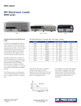
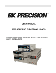
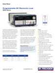
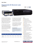
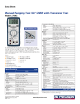
Data Sheet
DC Electronic Loads
8500 series
2400W
Versatile & Economical DC Electronic
Loads
600 W - 1200 W
The 8500 family offers 10 mode ls with a wide range of ratings
The 8500 series Programmable DC Electronic
Loads can be used for testing and evaluating a
variety of DC power sources. Their wide operating ranges of up to 500 V and 240 A, flexible
operating modes and excellent measurement
accuracy make the 8500 series well suited for
characterizing DC Power supplies, DC-DC
Converters, batteries, fuel cells and solar cells.
The loads can operate in CC, CV, CR or CP
mode while voltage/current or resistance/power
values are measured and displayed in real time.
Load terminals are isolated and floating.
Extensive protection, including over temperature, over power, over voltage, over current and
reverse polarity will help protect your valuable
prototype.
The DC loads are easy to use. All parameters
can be set quickly and precisely from the front
panel, or programmed via RS232 or USB interfaces.
Model#
Power
Ope rating Voltage
Rated C urrent
8500
300 W
0.1 - 120 V
30 A
8502
300 W
0.1 - 500 V
15 A
8510
600 W
0.1 - 120 V
120 A
8512
600 W
0.1 - 500 V
30 A
8514
1200 W
0.1 - 120 V
240 A
8518
1200 W
0.1 - 60 V
240 A
8520
2400 W
0.1 - 120 V
240 A
8522
2400 W
0.1 - 500 V
120 A
8524
5000 W
0.1 - 60 V
240 A
8526
5000 W
0.1 - 500 V
120 A
When selecting a DC load, it is important to
consider not only voltage and current
requirements, but also power ratings. The power
used when testing must fall within the hatched
region for the appropriate DC load.
Inpu t voltage
Rated power
I npu t cu rrent
Technical data subject to change
© B&K Precision Corp. 2013
300 W
w w w.bk prec ision.c om
Tel.: 714.921.9095
Some applications may require high voltage/low
current and low voltage/high current which a
single load may not be able to handle. B&K
Precision’s broad range of DC loads will allow
you to select the optimal model for your
requirements.
DC Electronic Loads
Models 8500, 8502, 8510, 8512, 8514, 8518, 8520, 8522, 8524, 8526
Features
■
Constant current (CC), resistance (CR), voltage
(CV) and power (CP) operation
■ Wide
voltage and current range, 0 to 500 V, 0
to 240 A (5000 W max)
■ Low
minimum operating voltage of < 0.1 V
and minimum input resistance of 5 mΩ (model
8518) allowing the load to sink high current at
low voltages, required for fuel and solar cell
applications
■ Selected
models operate up to 500 V, suitable
for high voltage applications
■ Built-in
■ Short
transient generator
circuit test
■ Built-in
high resolution (0.1 mA/1 mV) voltage
Applications:
and current measurement (models 8500 &
■ DC
8502)
■ Characterization
■ Bright,
easy to read display (VFD technology)
■ Over-Current/Over-Voltage/Over-Power/Over-
power supply testing
battery test mode is provided that will measure
the ampere*hour (A*hr) characteristic of a
battery
Temperature Protection
to TTL, USB to TTL serial
■ Fuel
converter cables and application software
■ High
■ RS232
of rechargeable batteries. A
and solar cell test
voltage applications
included
■ List
mode operation for increased throughput.
■ Battery
testing mode to provide A*hr rating
of battery (ending voltage level is adjustable)
■ Flexible
triggering: Create trigger events by
front panel keystroke, back panel TTL signal,
or software
■ Remote
voltage sensing to compensate for the
effect of voltage drop in wires.
■ Store
25 instrument setups
■ Thermostatically-controlled
fans allow
operation in quiet environments with minimal
disruption
■ All
Low voltage operation
The 8500 series can operate well below 1 V
which is important for low voltage application
such as fuel cell and solar cell testing. All models
can regulate (provide a stable input) down to
0.1 V. Model 8518, due to its particularly low
input resistance, can operate at full scale current
of 240 A at 1.2 V (see image)
models are rack mountable. Compact 300
W and 600 W models for bench use
Typical minimum operating voltage at full scale current:
8500
1.05 V
2
8502
3V
8510
1.8 V
8512
3V
8514
1.92 V
8518
1.2 V
8520
10.8 V
8522
3.6 V
8524
1.56 V
8526
1.8 V
w w w.bk prec ision.c om
DC Electronic Loads
Models 8500, 8502, 8510, 8512, 8514, 8518, 8520, 8522, 8524, 8526
▲ Front panel
1
2
The numeric keys and rotary knob provide a
convenient interface for setting the operating
mode and desired current/voltage/resistance
levels quickly and precisely. Voltage and current
can be set to a maximum resolution of 1 mV and
0.1 mA respectively (models 8500 and 8502
only). Up to 25 different instrument setups can
be stored and recalled from internal memory.
1 ) High re solution, easy to read display
Displays set values and measured values.
Current/voltage and power/resistance displays
can be toggled. Display resolution for current
and voltage is user-selectable. Maximum
resolution for model 8500 and 8502 is 1 mV/
0.1 mA.
3
4
5
Hex-head sc rew t erminals
2)
Convenie nt d ata e ntry
Rotary knob for quick analog-style control. Turn
to adjust a setting value. Press to toggle
measurement display mode.
4) Function keys
Activate current, voltage, power, or resistance
modes and scroll through menus and options.
3)
5) Front panel load terminals
Connect to device under test. Hex-head screw
Numer ic keypad
Conveniently enter set values directly and access
secondary functions.
1
▲ Rear panel
1) Air vents
Temperature-controlled fan expels air through
these vents to keep the temperature constant
inside the system.
3 ) Interface connection
Serial interface connector for RS232 or USB
communication.
2)
4) Voltage switch
Line voltage selection switch (110 VAC or 220
VAC).
Trigge r and remote sensing terminal
block
Connect sensing lines to this terminal to
compensate for voltage drops due to load wire
resistance. This terminal block also contains the
two connections for the remote TTL trigger input
signal.
terminals are used for models 8518 and
8520 – 8526 to connect wires.
3
3
2
4
w w w.bk prec ision.c om
DC Electronic Loads
Models 8500, 8502, 8510, 8512, 8514, 8518, 8520, 8522, 8524, 8526
▲ Flexible operating modes
C C, CR, C V and CP mod e
In Constant Current (CC) mode, the load will
sink a current according to the programmed
current value regardless of the input voltage.
(CC) mode can be used for load regulation
testing of DC power supplies or for characterizing the discharge profile of a battery.
Constant Power (CP) mode simulates a load
whose power consumption is independent of the
applied voltage. Constant Power (CP) mode is
useful for battery testing and simulating a
realistic discharge curve.
In Constant Voltage (CV) mode, the load will
attempt to sink enough current to control the
source voltage to the programmed value. This
mode is suitable for testing battery chargers.
In Constant Resistance (CR) mode, the load will
sink a current linearly proportional to the input
voltage in accordance with the programmed
resistance. Unlike conventional resistors, the
load resistance stays constant regardless of the
power level.
Transient g enerator
The 8500 series offers a variable frequency
generator which can be used in all operating
modes. The DC load will toggle between 2
preset levels at a frequency between 0.1 Hz to
1 kHz, either continuously or controlled by a
trigger.
Model 8500
Trigg ere d ope ration
Triggering is used to allow synchronization of the
DC Load's behavior with other events. You can
generate a trigger event by front panel keystroke,
by applying an external TTL signal to the back
panel terminal or by sending a commands over
the serial bus. The trigger can be used in pulse
mode, transient mode, list mode and works in
CC, CR, CV and CP modes.
▲ Remote control & application software
The DC loads can be remotely controlled from
any PC with USB or RS232 interface, allowing
the user to fully program and monitor all
parameters. RS232 to TTL and USB to TTL
serial converter cables are included. For users
wanting to write their own custom software, a set
of example programs are available for download
on the B&K Precision website.
List Mode
A list of command sequences can be stored in
non-volatile memory and executed independently
of a computer. Execution in list mode greatly
reduces command processing time and computer
interaction during product testing. The command
sequence can be entered manually from the front
panel or downloaded from a PC via RS232 or
USB interface.
Application Software
The included Application Software supports front
panel emulation of the load and includes a
battery test application which provides A*hr
rating of a battery and adjustable ending voltage
levels (safety voltage).
4
An example of battery discharge characteristics of an AA alkaline battery.
Whether you are designing a device with
Nickel-Metal Hydride or Lithium-Ion batteries,
the 8500 series have the capabilities to test their
characteristics.
w w w.bk prec ision.c om
DC Electronic Loads
Models 8500, 8502, 8510, 8512, 8514, 8518, 8520, 8522, 8524, 8526
Specifications
▲ Models 8500 & 8502 (300 W)
Parameter
Voltage
Current
Power
Input rating
Parameter
8500
8502
0 to 120 V
1 mA to 30 A
0 to 500 V
1 mA to 15 A
300 W
Range
8500
CV Mode
Regulation
CC Mode
Regulation
Accuracy
0.1-18 V
0.1 – 120 V
0–3A
0 – 30 A
0–3A
0 – 30 A
Current Measurement
Voltage Measurement
Resolution
8502
±(0.05%+0.02% FS)
±(0.05%+0.025% FS)
±(0.1%+0.1% FS)
±(0.2%+0.15% FS)
±(0.1% + 0.1% FS)
8500: ±(0.2%+0.15% FS)
8502: ±(0.2%+0.3% FS)
±(0.02% + 0.02% FS)
±(0.02% + 0.025% FS)
0.1 – 500 V
0–3A
0 – 15 A
0–3A
0 – 15 A
0-18 V
0-120 V
0 – 500 V
1 mV
10 mV
0.1 mA
1 mA
0.1 mA
1 mA
1 mV
10 mV
▲ Models 8510/8512/8514/8518 (600 W & 1200 W)
Parameter
Input rating
8510
Voltage
Current
Power
8512
0 – 120 V
0 – 120 A
0 – 500 V
0 – 30 A
600 W
Parameter
CV Mode
Regulation
CC Mode
Regulation
Current Measurement
0-12 A
0-12 A
Voltage Measurement
8512
8518
0 – 60 V
0 – 240 A
1200 W
Range
8510
8514
0 – 120 V
0 – 240 A
Accuracy
8514
0.1-18 V
0.1 V to Vmax
0-3 A
0 – max Current
0-3 A
0 – max. Current
0 – 18 V
Resolution
8518
±(0.05%+0.02% FS)
±(0.05%+0.025% FS)
±(0.1%+0.1% FS)
±(0.2%+0.15% FS)
±(0.1% + 0.1% FS)
±(0.2%+0.15% FS)
8510/8514: (0.02% + 0.025% FS)
8512/8518: (0.02% + 0.02% FS)
±(0.02% + 0.025% FS)
0-24 A
0-24 A
0 - Vmax
1 mV
10 mV
1 mA
10 mA
1 mA
10 mA
1 mV
10 mV
▲ Models 8520/8522/8524/8526 (2400 W & 5000 W)
Parameter
Input rating
Voltage
Current
Power
8522
8524
0 – 500 V
0 – 120 A
0 – 60 V
0 – 240 A
2400 W
Parameter
0-24 A
0-12 A
8522
0.1-18 V
0.1 V to Vmax
0-12 A
0-24 A
0 – max Current
0-3 A
0-24 A
0 – max. Current
0 – 18 V
0 - Vmax
5
Accuracy
8524
Voltage Measurement
8526
0 – 500 V
0 – 120 A
5000 W
Range
8520
CV Mode
Regulation
CC Mode
Regulation
Current Measurement
8520
0 – 120 V
0 – 240 A
Resolution
8526
0-12 A
0-12 A
±(0.05%+0.02% FS)
±(0.05%+0.025% FS)
±(0.1%+0.1% FS)
±(0.2%+0.15% FS)
±(0.1% + 0.1% FS)
±(0.2%+0.15% FS)
8522/8526: (0.02% + 0.02% FS)
8520/8524: (0.02% + 0.025% FS)
±(0.02% + 0.025%FS)
1 mV
10 mV
1 mA
10 mA
1 mA
10 mA
1 mV
10 mV
w w w.bk prec ision.c om
DC Electronic Loads
Models 8500, 8502, 8510, 8512, 8514, 8518, 8520, 8522, 8524, 8526
▲ Common characteristics
Parameter
Range
Accuracy
Resolution
0.1 -10 Ω
±(1%+0.3% FS)
0.001 Ω
CR Mode Regulation
(Input current ≥ FS 10%
Input voltage≥ FS 10%)
10-99 Ω
±(1%+0.3% FS)
0.01 Ω
100-999 Ω
±(1%+0.3% FS)
0. 1 Ω
1K-4 KΩ
±(1%+0.8% FS)
1Ω
0-100 W
±(1%+0.1% FS)
1 mW
100 W - max power
±(1%+0.1% FS)
100 mW
0-100 W
±(1%+0.1% FS)
1 mW
100 W - max power
±(1%+0.1% FS)
100 mW
CW Mode Regulation
(Input current ≥ FS 10%
Input voltage≥ FS 10%)
Power Measurement
(Input current ≥ FS 10%
Input voltage ≥ FS 10%)
Other
Battery testing function
Input = 0.1 V – 120 V, Max measurement capacity = 999 Ah
Resolution = 10 mA, Timer range = 1-60000 sec
Transition mode
Range of Frequency 0.1 Hz-1 kHz, Frequency error rate 0.5%
Power input
110 / 220 (see note below)* VAC ± 10%, 47 – 63 Hz
Operating temperature
32 ºF - 104 ºF (0 - 40 ºC)
Storage temperature
50 ºF - 140 ºF (10 - 60 ºC)
Humidity
≤ 95% relative humidity, non-condensing
Safety
EN61010-1:2001, EU Low Voltage Directive 73/23/EEC amended by 93/68/EEC
Electromagnetic compatibility
Meets EMC Directive 89/336/EEC amended by 93/68/EEC, EN50081-1, EN50082-1
One-Year Warranty
* All 8500 series models, with the exception of models 8524 and 8526, can be configured for 110 V or 220 V operation via the AC line switch in the rear
panel. Base models 8524 and 8526 operate with 110 V only. For 220 V operation, order model 8524-220V or 8526-220V respectively. “-220V” denotes
220 V operation only and these models cannot be reconfigured for 110 V operation.
▲ Mechanical specifications
Model
Dimensions (W x H x D)
Weight
8500
8.46” x 3.46” x 14” (215 mm x 88 mm x 355 mm)
11.5 lb (5.2 kg)
8502
8.46” x 3.46” x 14” (215 mm x 88 mm x 355 mm)
11.5 lb (5.2 kg)
8510
16.9” x 3.46” x 14” (429 mm x 88 mm x 355 mm)
31 lb (14 kg)
8512
16.9” x 3.46” x 14” (429 mm x 88 mm x 355 mm)
31 lb (14 kg)
8514
16.9” x 3.46” x 14” (429 mm x 88 mm x 355 mm)
31 lb (14 kg)
8518
16.9” x 3.46” x 14” (429 mm x 88 mm x 355 mm)
31 lb (14 kg)
8520
17.48” x 7.09” x 21.22” (444 mm x 180 mm x 539 mm)
66 lb (30 kg)
8522
17.48” x 7.09” x 21.22” (444 mm x 180 mm x 539 mm)
66 lb (30 kg)
8524
17.48” x 14.06” x 21.22” (444 mm x 357 mm x 539 mm)
148 lb (67 kg)
8526
17.48” x 14.06” x 21.22” (444 mm x 357 mm x 539 mm)
148 lb (67 kg)
▲ Accessories
Standard
Optional
6
v061813
Power cord, user manual, installation CD with application software, RS232 to TTL serial converter cable IT-E131,
USB to TTL serial converter cable IT-E132
Rack mount kit IT-E151 for models 8500, 8502, 8510, 8512, 8514 and 8518 only
w w w.bk prec ision.c om