1
a
INK
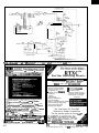
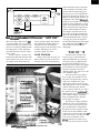
A Look at Next Year
e’re qprwching the end of another editorial
year, and many of you are anxious to find out what
we have h stare for the next year. Before I list the
upcoming themes, let me take a moment to encourage you
tokokatthelistwithaneyetowardmitinganarticle.Doesoneofthe
themescomedosetowhatyoudoinyoureverydayjob?Perhapsyoujusl
fffished a project that relates to one of the topics. lf so, chances are you’ve
fsarned a few trfcks that would surely beneft your fsbw readers.
Don’t assume that just because you’re comfortable with a basic.
cancept,everyoneelseisjustascomfortable.Writeanarticletoshowoff
what you know and everyow will benefit from your knowledge. For example,
if you work with analog circuits all day long, your expsrtise can go a bng
wayinfwfpingsomeone whose jcb doesn’t extend mush past bits and bytes.
what’s that? You’ve never written an article and woukfn? know where
to begin? Nonsense. Bounce your kfeas off us and we’1 be happy to work
wtth you to structure a welt-written article in no time. What’s important is that
you know ywr stuff and you take that first step by contacting us with your
‘k&as. You may call me at (203) 875-2199, leave me a message on the
Circuit cellar BBS ([203] 87%1988) send me a fax ([203]872-2204) or put
your ktaas on paper and send them by mail (4 Park St., Vernon, CT ososS).
Now for next y&s themes. 1’11 have some spsciflc dates for you in the
next issue, but I diinY want to put off telling you about the topiff.
CIRCUIT CELLAR m k] a o
THE COMPUTER
APPLICATIONS
JOURNAL
NANAGING EDITOR
KenDavidson
PUBLISHER’S ASSISTANT
Susan McGill
AS!3OClATE EDITOR
Lisa Nadile
CIRCULATKIN COORDINATOR
Rose Manseila
CIRCULATKIN ASSISTANT
Bark%aMalesu
ENGINEERING STAFF
JeffBachiinchi&EdNisiey
CIRCULATKIN CONSULTANT
Gregory SpiQfadsn
WEST COAST EDllOR
Tom Cantrell
BUSINESS MANAGER
JaannetIe Walters
CONTRlBllTlNG EDITOR
John Dybowski
ADVERTlUNG COORDINATOR
Dan Gomky
NEW PRODUCTS EDlTOR
Hatv Weiner
ClRCUtT CELLAR INK (!SSN -1 k
ART DIRECTOR
Lisa
ruu&hedbimar~bruf~1~hwxpofa~*
Ferry
4PallcSwtSdb20,vemm,CT06066(203)
87w751. Secmddam pwbp pdd at Yamon,
STAFF RESEARCHERS:
NOtthO8St
John Dybomki
CldddkddflCSCW-pX(6i~
altx@Im ram USA a-d poBwKka was
-s2t.%.05~mmm~~
Al#ANa@km~p~inu.S.~anly.
wmma~~mmey~~~~dmnl
Mdwmt
Jon Eison 8 Tim McDonough
wesl coast
antJ.S.MrDtfrct~adaabctc*l
CdWNK.SutwWn&P.O.Bo:3050C.Sa*c
ea8bm,PA19%3ad1(215l53@1914.
PC6TMwERPlaaflsmd~eMdwlp
b Ciwlt cekr YK. CM&II Depl. P.O. SLV
3959.C. soutulem. PA 1939(1.
Frank Kuechmann
Home 8 Building Automation
Real-Tiie Programming
Communication
Graphics 8 Vi
Power Control (L convers*bn
Data Acqufsii
Embedded Interfacing
Siinal Condiiioning
Signal Procassing
Measuremsnt&Control
Programmable Devices
Embedded Control
Nothing catches your eye, but you have some other ideas? That’s CIK,
too. There is often room in each issus for an article that doesn’t strictly fti
that issue’s theme, so we stil want to hear about those ideas.
BACK TO THE PRESENT
We’re hard at work judging this year’s Circuit Cellar Design Contest
entries and we’ll have the results in the next issue. In the meantime, we
have two art&s in thii issue wrftten by past Design Contest winners. The
MC68HC1 l-based twodimansbnal sensor usad with a geranium-planting
robot won first pface in the General Category last year and the Time Domain
Reflectometer won first place in tha Cost-Effedive Category the year before.
Be sure to keep an eye out in future issues for our new 9esiin
Cnntast Wnner” logo that now marks an author as one of the best.
2
Issue 128 August/Sepember, 1992
The Computer Applications Journal
PUBLISHER
Daniel Rodrigues
FOUNDERIEDtTORIAl DIRECTOR
stew Ciarcia
Covet
lllustratk~ by Robert Tinnay
HAJAR ASSOCIATES NATIONAL ADVERTISING REPRESENTATIVES
NORTHEAST
;y; ytAngrSen
Fax: (617) 769-8982
SOUTHEAST
ChrIsta Colllns
W) 96&3939
Fax: (306) 9858457
hUD.ATLANTK:
MIDWEST
Fax: (90s) 741-6623
(706) 7893060
Fax: (706) 789-3082
Barbara Best
(!208) 741-7744
Nanette Traetow
WEST COAST
Barbara Jones
;,:;zplney
1ax: (714) 540-7103
12
22
34
q
q
‘ 1
1
Planting Geraniums by Robot/Build an MC68HCll -based 2-D Sensor
by Brian Farmer
The Design of a Time Domain Reflectometer
by Brian Kenner and John Wettroth
Serial l/O on the IBM PC
by Jim Schimpf
Add Text Overlay to Any Video Display
by Bill Houghton
The Virtues of the Hue, Lightness, Saturation Color Model
by James R. Furlong
Driving Multiple VGA Monitors
by Michael Swartzendruber
I
Editor’s INK/Ken Davidson
A Look at Next Year
Practical Algorithms/John Dybowski
The Middle Ground/Negotiating a Keyboard Interface
New Product News
edited by Harv Weiner
ConnecTlme-Excerpts from the Circuit Cellar BBS
conducted by Ken Davidson
Firmware Furnace/Ed Nisley
Steve’s Own INK/Steve Ciarcia
Let Me Tell You About Yourself
Extending Your Control: The HCS II MCIR-Llnk
From the Bench/Jeff Bachiochi
X-10 Interfacing with PUX
Advertiser’s Index
Slllcon Update/Tom Cantrell
I’m 18.432-and I Like It
The Computer Applications Journal
Issue #29 October/November, 1992
3
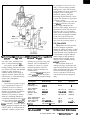
UNIVERSAL DEVICE
PROGRAMMER
The first device
programmer in production offering a single
universal PLCC socket
has been announced by
B&C Microsystems Inc.
The new socket technology of the Proteus104
accommodates any
PLCC device from 20 to
84 pins, reducing PC
board traces and capacitance on the programmer
header. A 48-pin ZIF
socket is mounted
alongside for programming 300- and 600-mil
DIP devices.
The ProtCuslO4
features fully overvoltage- and overcurrentprotected pin drivers, full
digital and analog
capabilities for all pin drivers, true system self-calibration of all voltage sources and full diagnostics of all pin
drivers, a built-in controller and timer with 250-ns
resolution, and state machine testing with rise and skew
time of less than 10 ns.
The ProtCuslO4 also features expandable pin driver
boards, allowing upgrades to any level within its 24- to
1OCpin range. An entry-level version with 24-pin drivers
and a 40-pin ZIF socket is the base configuration. For
production environments when programming MOS
devices, gang (parallel) modules replace the universal
module and provide higher throughput to meet manufacturing needs by providing eight or sixteen ZIF sockets.
Also available is a memory card gang module (supporting
PCMCIA 2.0 Standard] with sixteen sockets.
The programming and algorithm development
environment is based on a single executable file with a
built-in editor and compiler for fast software development and ease of use. Semiconductor manufacturers use
a powerful Algorithm DEvelopment Language (ADEL) in
the creation of new device algorithms. ADEL can also
make changes to existing algorithms, when revisions are
required, and can drastically reduce turn-around time for
the user of the devices. An extension of ADEL allows the
creation of special test algorithms independent of those
officially published ones embedded in the Prottusl04
system.
6
Issue W29,October/Movembr, 1992
The Computer Applications Journal
Communication with any PC, XT, or AT is via a
parallel printer port, which has been optimized for the
fastest and most reliable performance. The speed limita
tions exhibited by PC bus-based programmers are absent
The parallel port is searched by the programmer and the
connection made automatically. All device library
software is available through a Bulletin Board System or
by floppy diskettes.
The ProtCuslO4 is priced from $745 to $4995.
B&C Microsystems, Inc.
750 N. Pastoria Ave.
Sunnyvale, CA 94086
(408) 730-5511
Fax: (408) 730-5521
#500
LOW-COST
NETWORKED
MICROCONTROLLER
The GCBll, an g-bit
networked microcontroller hardware and software
package, has been announced by Coactive
Aesthetics Inc. The 3” x
4” board, based on the
popular Motorola MC68HC 11 F 1 chip, includes
32K of static RAM, 32K of
ROM and requires only a
+5-volt supply.
The GCBl 1 includes
20 digital I/O lines and
eight channels of g-bit
A/D conversion. Communication is provided by a
standard RS-232 port and
an RS-485 port for a
multidrop network with
up to 32 nodes. Additional
485 drivers are on board
for connecting a PC using
the RS-232 to the RS-485
network, without the
need for additional
circuitry or boards. The
boards can be jumper
configured as either a
master or a slave on
the network, and
code can be downloaded and debugged
across the network.
The GCBl 1
Package comes with
a complete set of
development tools
and network and
application libraries.
The GNU C crosscompiler operates
under PC-DOS and
includes support for
C++ and Objective C.
The GNU Linker is
also included. The
ROM Monitor-Debugger
allows program downloads
in S-record format. Break
points can be set and single
step/step over execution is
provided. Read and modify
features are provided for
memory, CPU registers, I/O
registers, EEPROMS, and
ports. An assembler and
disassembler are also
included.
Master-slave packet
communications software
LOW-COST 8051 C PACKAGE
Franklin Software’s new Engineer’s Evaluation Kit,
Release I, is a complete C programming package for 805 1
development at the price of a standard 805 1 assembler.
The kit targets engineers and students who have tried
earlier C products and found them either too weak and
slow or too expensive. The kit allows you to experience
the power and efficiency of an advanced C for 805 1
software development and maintenance.
Based on technology developed for Franklin’s Professional Developer’s Kit, the Evaluation Kit includes a C
compiler, a macro assembler, a linker, a powerful symbolic debugger-simulator, C libraries, and utilities. The
kit features fast compilation and highly optimized object
code. Execution speed is comparable to the best in the
industry, and performance is equal to a tightly coded
assembler.
provides rapid development
of distributed control
applications at various baud
rates up to 115.2 kbps.
Application utilities include
a PWM motor driver library
for transparent support of up
to four DC motors, encoder
feedback for speed and
position control of up to
three motors, input signal
debounce library, and
support for ADC sampling
at regular intervals as a
background task Source
code for all software is
provided (C and assembler]
The complete GCBl 1
package sells for $179.
f&active Aesthetics, Inc.
P.O. Box if425967
San Francisco, CA 94142
(415) 626-5152
Fax: (415) 626-6320
#so1
The Engineer’s Evaluation Kit is an entry-level
companion to, and fully upgradable to, Franklin’s
Professional Development Kit for the 805 1. Priced during
introduction at $299 plus an optional support contract,
the C kit is an affordable way for engineers to discover
the advantages of a complete C environment for 8051
development.
Franklin Software, Inc.
888 Saratoga Ave., #2
San Jose, CA 95129
(800) 2834080 Ext. 896
Fax: (468) 296-8061
#502
The Computer Applications Journal
leeur #29 OctobedNovember, 1992
7
PROGRAMMABLE RELAY CONTROLLER
PROVIDES ANALOG AND DIGITAL SUPPORT
A family of programmable relay controllers with
both analog and digital I/O capabilities for low-end
control and sensor interface applications has been
introduced by DIP Inc. The Pica PLC units provide
digital, analog, PWM, RS-232 I/O, and an auxiliary
sensor power supply. Integrated programming and
debugging support allow the PPLC to be programmed
using a standard data terminal or PC. No specialized
programming software is required.
Extending the control language typically found in
low-end PLC units with a full set of arithmetic and
comparison operators, the PPLC products allow the user
to intermix analog and digital operations using ladderlogic-formatted command strings. The unit may be put
into a single step or display mode for interactive debugging. File transfers are supported to and from a PC
programming unit using standard PC-based communications packages. EEPROM program storage provides for
256 program elements with an average execution time of
50 ps per element.
The PPLC will replace combinations of discrete
relays, counters, timers, and comparators in applications
such as production monitoring, intelligent sensor
interfaces, front-end preprocessing for larger programmable controllers, sequence control, and low-end motion
control systems requiring peripheral interfaces. A
comprehensive programming guide cuts the learning
time to less than two hours.
The base unit (PPLC) provides four inputs (120
VAC), four outputs (120 VAC, 2 amps), two analog
channels (O-IO VDC), a PWM output (open collector), an
RS-232 serial channel, and a sensor supply voltage of 12
VDC at 200 mA. The entire unit is packaged in a 2.75” x
3” DIN-rail-compatible case with captive screw terminals. A board-level version (PPLC-BRD) extends the I/O
to eight inputs, eight outputs, and four analog inputs.
Both units sell for $239 in single quantities.
DIP Industrial Products
P.O. Box #9550
Moreno Valley, CA 92552
(714) 924.1730
Fax: (714) 924-3359
#503
8
Issue #2# Octokr/November, 1992
The Computer Applications Journal
PC-BASED MOTION
CONTROLLER
MicroKinetics Corporation has introduced
Quickstep, a new stepper
motor controller containing
on-board translators and
power drivers for up to three
axes all on one card. It is
designed for cost-sensitive
applications that do not
require very high stepping
speeds and where the
convenience of having the
indexers and drivers on one
card is important. The
Quickstep plugs directly
into any 8- or 16-bit ISA bus
IBM PC or compatible,
eliminating the need for an
external enclosure.
Features include
programmable acceleration
and deceleration, automatic
overtemperature protection,
end-of-travel detection on
all axes, two auxiliary
outputs per card, and a
shield-open interrupt. The
Quickstep operates interactively; no uploading or
downloading of programs is
required. It provides
keyboard control of such
functions as Jog, Pause,
Abort, and so forth, and
drives motors requiring up
to 0.9 amps at 12 VDC. A
built-in timer assures motor
speed consistency regardless
of computer speed. The
Quickstep requires only one
g-bit slot and features
programmable address
selection to allow coexistence with other cards that
may otherwise cause
address conflicts.
The software is very
easy to incorporate into
any application. The
included subroutine
libraries support C and
QuickBasic, and feature
linear and circular
interpolation, ramping,
keyboard interactive jog,
and electronic gearing.
The QuickStep motor
controller sells for $389
for a three-axes system.
One-axis and two-axes
systems are available for
less.
MicroKinetics Corp.
1220 Kennestone Cir., Ste. J
Marietta, GA 30066
(404) 422-7845
Fax: (404) 422-7854
604
HARD DRIVE ENCYCLOPEDIA
The “Micm House Encyclopedia of Hard Drives” is
now available from Jensen Tools. This unique, threevolume support tool provides comprehensive technical
help for the installation and upgrade or maintenance of
multivendor hard drives. It contains information on
hundreds of drives from Alps to Zebec, including many
discontinued makes and models. The information is
loose-leaf bound in three-ring binders to make page
replacement and update easy, and comes with a fast, easy
software version on DOS 5.25” diskettes.
Included are separate volumes on setup, controller
cards, and drive settings. The information includes
everything service professionals need to know about
switch settings, cable locations, configuration parameters, power specifications, error codes, and interface
basics for ST506/412, SCSI, ESDI, IDE, floppy, and more.
Clear drawings detail switch settings and cable connections for both drives and controller cards. Also included
are BIOS tables and a complete index of manufacturers
with contact information.
The $595 Solution
to 8051 Sjatem Development
The “Micro House Encyclopedia of Hard Drives”
(Part #764B880) is featured in Jensen’s Catalog Supplement D and costs $150.
Jensen Tools, Inc.
7815 S. 46th St Phoenix, AZ 86044 (602) 968-6241
l
l
605
PRODUCT DEVELOPMENT
*
MADE EASY! *
With -feature packed SLnQle Board Copters and easyfn
yse BASIC comoiieLyour productlappliition can become a reality in
no time. EMAC’s BASIC compiler allows you to develop the software
right on thesingle BoardComputer. Nornoretimelostlinking, downloading, or burning EPROMs. immediately see the results of a program
change. Make modifications or dump memory right on the board. Since
this BASIC is compiled and written entirely in assembly language, your
programs will fly. Full flow. functions,
Detworb ail at your fingertips. But you say you need multltasklng;
how about up to 32 tasks with priority scheduling built in. No adding
libraries. And this multitasker is as easy to use as the BASIC language.
If BASIC is not your language of choice, EhMC offers Assembl r. Al&l
md Forth - you choose. But enough about the software, sokare is
nothing without a good hardware foundation with the features you need
to make the job easy. Need to drive relays? Take advantage of I!J&II
drive d altal outPut ilneq. Have some digital input lines that are kind of
noisy? LliiizeBo&lc~. You can also take advantage
ie l/O lines. 6 timerlcounters. and 4 serial
The PDK51 i) a fully intcgrdted
hardware, firmware,
,. and wftware
we supply the wst.
PDK51 PLUS includes everything in the PDK51 plus Vers. 3 of OUI
popular BXC51 8051/8052 BASIC compiler-$800.
Call Now! 508-369-9556 or FAX 508-369-9549
q
Binary Technology, Inc.
P.O. Box 541
l
Carlisle, MA 01741
WIf33
~andth~WXOOOG2canhandle
iust about anything. The EeG2
ElildC inc
618-529-4525
FAX:6i f3-457-O?iO
P.O.BOX 2042 CARBONDALE, IL 62902
9
SOLID-STATE DISK SYSTEM FEATURES
REMOVABLE MEMORY CARD
The MNC 1150
high-speed solid-state
“disk” system features a
removable PCMCIA 2.0
memory card slot for ISA
and FJSA computers. The
MS-LXX-compatible
system stores files in fast
semiconductor memory
rather than mechanical
disks to achieve the high
speed without wear. The
on-board BIOS ROM
allows instant-on and
instant-reset capability.
The MNC 1150
offers complete PCMCIA
2.0 compatibility, which
can support memory
cards up to 64 megabytes
with a 16-bit data
path. In addition,
eight 32-pin JEDEC
sockets for SRAM,
EPROM, EEPROM,
and flash memory
chips are provided
(for a total storage capacity
of 72 megabytes]. It has
been designed with CMOS
technology using a versatile
register-based interface with
error sensing and selectable
interrupts to ensure data
integrity in critical environments.
The PCMCIA 2.0 card
socket is accessible through
the card bracket, so memory
cards can be loaded and
unloaded while the computer system is operating.
Dual-battery backup is
provided for the JEDEC
sockets when SRAM is
used. On-board flash
memory programmer and
support software is provided. Power requirements
are less than 1 amp at 5
volts and up to 250 mA at
12 volts (when programming flash memory).
Evaluation units are
available for $295 with
zero memory.
MNC International, Inc.
2817 Anthony La. South
Minneapoils, MN 55418
(612) 766-1099
Fax: (612) 766-9365
#SO6
2”~ 4” EMBEDDED PC
“Megatel Wildcurds provide -PC functional& in a fIexi6le,
Wihrd 88’”
l
l
l
l
CPU clock to 10 MHz
Replaces full PC motherboard
Co-processor and BIOS socket
DMA, Bus, DRAM, Keyboard
controllers
l
l
l
Multi/IO
On-board SCSI Host Adapter
(supports up to 7 devices)
Floppy Controller (1.44M, l.2M)
2 RS-232. I Parallel. I RS-485
multi-protocol serial port
All Wildcards are low power single +5 volt operation.
125 Wendell Ave., Weston, Ont. M9N 3K9 Fax: (416) 245-6505
Vid/Mem:
l
l
640Kb User memory
Videokolour LCD controls
CGA, Hercules@, IBM@ Mono;
(runs LCD Panels)
For information on our representatives please
contact our head office at ‘tie number beh
(416) 245+3324
Wildcard 88 and Megatel are trademark. of Megatel Computer Corp. Hercules is a trademark of Hercules Corp IBM is a trademark of IBM Corp
10
megatel@
#IO5
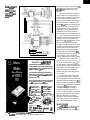
Planting Geraniums
by Robot
Brian Farmer
The Design of a Time
Domain Reflectometer
Planting Geraniums
by Robot
I
Serial 110 on the
IBM PC
Build an
MC68HCllbased
2-D Sensor
12
issue 129 October/November, 1992
The Computer Applications Journal
pposites attract,”
so the saying goes.
Maybe it’s true with
people, but definitely not
with robots and flowers. Even though
the latter are about as opposite as can
be, they don’t attract. Matter of fact,
they are about as incompatible as you
can get. Robots are inclined towards
uniformity, and flowers are inherently
diverse. That’s where my sensor comes
in, providing a necessary ingredient for
a marriage that would otherwise never
work, or technically speaking, assisting a robotic system to accommodate
nonuniformity.
Robotic systems aren’t anything
new. They’ve been around industry for
years, improving productivity and
quality and doing many hazardous or
uncomfortable tasks for workers. For
example, the automotive and electronics industries use robots to perform
repetitive and precise tasks. This form
of automation is implemented in
predictable and structured environments [l] with defined spatial configurations.
Agricultural robotics ventures
beyond the predictable to the unpredictable environment. No formal
methodology exists for designing
automation systems that work with
biological products that are of variable
bend
sensor
arrays
stripping device
for propagation to be used as a case
study. A conveyor brings geranium
cuttings into a robot work envelope.
Using machine vision, the supervisory
computer locates a cutting and
classifies all primary plant parts.
Knowledge of plant structure is used
to grade and determine an appropriate
processing strategy.
Control is passed to the robot and
end effector controllers. The robot
grasps a single cutting from the
conveyor with a gripper, moves it to a
pneumatic device for leaf removal (if
necessary), takes it to a pneumatic
cutter for stem trimming, and inserts
it into a plug of propagation medium
[in this case, peat). Fixtures and
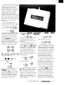
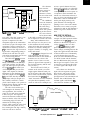
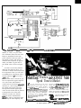
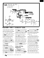
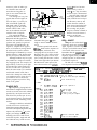
sensors mounted within the workspace assist the processing (Figure 1).
THE CHALLENGE
The problem the robot had early
Figure l-The r&or’s job is to pick plant cuffings off a conveyor be/f frim leaves and fhe stem, and inserf the wlting
into a flw ofpeat The sensor help tie rotof compensate br the natural bend in the plant’s stem.
on was it damaged a significant
number of cuttings. Its strictly vertical
insertion motion into the plug did not
regard the bend in the geranium stem.
It could neither recognize different
relative angles of stem growth frequently found on cuttings nor the
change in stem orientation during
workcell preparation.
For the reliable insertion of
cuttings into plugs, the direction and
degree of bend at the base of the stem
had to be determined. Then, the robot
arm had to make the appropriate
moves to align the end of the stem
with the hole in the peat plug accurately.
size, shape, color, orientation, and
stress or strain relationships [2].
This scenario presents quite an
inviting challenge, and who can resist
one of those? Not many. Fundamental
research is widely underway to
establish methods for the design of
cognitive machines [robots) that can
autonomously or semiautonomously
operate with contingencies.
handling and processing living plant
materials. This accommodation of
variability is contrary to a typical
industrial application where an
attempt is made to eliminate any
inconsistencies.
Dr. Ward Simonton developed a
robotic workcell for the labor-intensive preparation of geranium cuttings
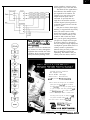
THE ROBOT
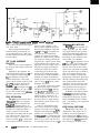
Company/item
Model Name/No.
Range
Type: LVDT
Schlumberger Ind.
ACW15
0.030 m
Type: Ultrasonic
Polaroid Corp.
Contaq Tech.
Ultrasonic Arrays
Cosense
Design Kit
UDM-Fit&J
DMS-100
ML-1 01
0.27 m-10.7 m
0.15 m-9.14m
0.005 m-6.61 m
0.02 m-2.74 m
0.003 m-3 m
0.0002 m
0.0002 m
0.00005 m
MP-6
SBF5 wllR2.53S
Edge Sensing Sensor
2-D, LS-3033 & LS-3100
3.05 m
0.025 m
0.025 m
0.03 m
0.013 m
Most robots are capable of repeating a preprogrammed sequence of
operations; however, for robots to
operate effectively in a changing or
uncertain environment, the machine
must be equipped with sensors.
Therefore, a key activity in robotics
research is examining methods for
coordinating information from various
sensors to control robotic actions [3].
At the Georgia Station Mechatronics Laboratory, research is investigating pragmatic techniques that allow
robotic systems to accommodate the
significant variability present when
Type: Optoelectronic
Banner Engineering
Banner Engineering
Frost Controls
Resolution
00
0.002~ m
0.000002 m
00 : Analog output; resolution primarily limited by measuring device.
Tabls 1--Numemus senscts are available that might have helped in thy& pmjecf, but none Cf Ihe proiecf criteti
The Computer Applications Journal
Issue 129 CctobedNovembsr, 1992
13
J-l
Analog
C..Z.^L
rtgurs z- Ine
on a tenninal screen.
Lhe whde measurement pcss. Resuk may be optbnaiy displayed
87C51
87C751
87C752
PIG
II7troducing the Most Expandable 3 l/2 Board Available
,
MCU-31/2
Free software updates on BBS
Powerful menu driven software
27CO40
93C46
XC1 736
up to 400 MHz
16K samples/channel
Variable threshold levels
8 External clocks
16 level triggering
Igfgq
(404) 35214788 ,9;;:f;;::,
Atlanta, GA 303 18
.
Parts added at your request
up to 128 channels
hAore I/O modules are availble.
3all for our FREE catulogue today!
_
5ns PALS
4 MEG EPROM (8 & 16 bit)~~~~o
22VlO & 26CV12 GALS
26CV12
from $149.95
On Board Options Include:
X 16 Channels 10 bit A/D -14~ w/S/H
I( Dallas 1287 RTC
X Flexible mem config’s: RAM - 8/32KB
ROM - 8/16/32/64 KB
X RS-232 or 485 -jumper selectable
X Watchdog timer w/ jumper sel. reset source
% Pre decoded external bus for very easy user interface directly compatible with other ADS boards
(see back issues of Circuit Cellar INK)
14
I considered several commercially
available sensors for the stem bend
measurement, including LVDTs,
ultrasonic transducers, and optoelectronics (refer to Table 1). With the
LVDT, physical contact between its
armature and the object sensed
requires force, resulting in deflections
and incorrect measurements due to
the elasticity of the geranium stem.
Ultrasonics (Contaq Technology)
can make noncontact measurements;
however, it needs relatively precise
insonification of the ultrasonic beam
on a specific area of a small object.
Standard collimating tubes do not
normally ensure a measurement
focused on a l- to 2-mm object
section. In addition, precision ultrasonic sensors are costly (Ultrasonic
Arrays & Cosense).
I then turned to commercial
optoelectronic sensors. Discrete
measurements from an arrayed
“curtain of light” would be possible
with an emitter-receiver pair for
binary blocked/unblocked detection. I
considered an b-channel Sensor
#107
Issue #29 October/November, 1992
The Computer Applications Journal
$799 - LA12100 (100 MHz,24 Ch)
$1299 - LA32200 (200 MHz,32 Ch)
$1899 - LA32400 (400 MHz,32 Ch)
Price is Complete
Pods and Software
included
Call (201) 808-8990
Link Computer Graphics, Inc.
369 Passaic Ave, Suite 100, ‘Fairfield, NJ OiOO4 fax.: 808-878(
#lC
Multiplexer Module (Banner), but it
has fairly poor resolution (5-12 mm].
Other light curtain devices offered by
Banner and Sick Optoelectronics
simply provide presence detection or
the edge measurement of a surface.
A 1-D C-shape sensor is available
from Frost Controls that measures an
object’s size using an analog signal
proportional to the area blocked, and it
also can be constructed to detect
position. However, this unit is 12.5
mm thick, which is the minimum
displacement between measured
dimensions. Due primarily to cost and
complexity, I did not consider the
various types of laser-based position
measurement systems (Keyence,
$14,400) for this application [4].
Evidently, no commercially
available position measurement device
fit the needs of this application, so I
developed a sensor and coupled it to an
MC68HCll microcontroller [5,6,7].
The pairing of the measuring element
and the inexpensive microcontroller
yielded an externally controlled
programmable sensor that reported
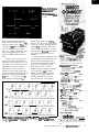
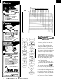
Photo l-The sen.wr uses paits of LEDs end pIwto&amisti b smse the psitkm
ho/e in Ihe middle.
measurement results through a
parallel/serial interface.
DESIGN CRITERIA
The primary design goal for my
sensor was that it detect the direction
FREE
CALL
of a @an1 cvf@ tierled h #m
and magnitude of bend on a geranium
cutting stem’s base relative to the
robot’s grasp. To make this determination, the robot is directed to position
geranium cuttings in a fixed location
in the workcell, then to measure
PARADIGM LOCATE l PARADIGM TDREM
l PARADIGM DEBUG l
Comprehensive software development tools for
all Intel Ml86 and NEC V-Series
microprocessors.
l
Borland C++ and Microsoft C/C++ support
Choice of stand-alone or in-circuit emulator
l
debugging
Unlimited toll-free technical support
l
30day money-back guarantee
l
He@ IS Available
Call today for complete
product information and embedded system
application solutions. You won’t be disappointed!
HELP
#lo9
PAR/jDlGM
Proven Solutihs for Embedded
C/C++ Developers
Paradigm Systems, 3301 Country Club I&ad,
Suite 2214, Endwell, NV 13760
TEL: (607) 748-5966 FAX: (607) 748-5968
Trademarks are property of respective holders.
SeeusafUteEmbeddedSysfemstiftrsncgsaoll,x3a5
Issue #29 Cktokr/Nove~r, 1982
15
The Computer Appliitii Journal
w-me DufK 01 me sensor s maUe UD of me LtD@wkWansimrpairs.
piti is tehg bbcked.
quickly the stem’s position with a
sensor. The bend of the stem is
referenced from the robot’s grasp point
to the bottom of the stem, and the
information is used when inserting the
cutting into the plug. Geranium
cutting stems are frequently 5-10 mm
in diameter with bends of O-O.6
radians. Before a stem has been
inserted into the plug, it generally
extends below the robot’s fingers 1520 mm.
Thus, the design criteria for the
sensor included a l- to 2-mm resolution, a 25mm range in two dimensions, a l-mm maximum displacement
between measured dimensions, and a
lOO-ms maximum response time.
Object size was assumed to be within
the range of 4-12 mm. Also, I needed
to keep component cost under $500. I
pursued a small, noncontact sensing
method because of the infrequent need
16
Issue X29 October/November, 1992
One at a time, each LED is /it and its companion photoft-mS&r is chedwd to find out if tte light
for cleaning and the absence of any
force applied to the plant stem, which
could affect the measurement or
disturb the cutting within the gripper.
THE SENSOR
In 1989, I developed the first
sensor for this application [4]. It was
based on two lo-element infrared LED
emitter and phototransistor receiver
pairs (Siemens LD260/ BPXSO) [8]
physically aligned as a 25-mm x 25mm square. Emitter-receiver pairs
were not multiplexed. The entire first
dimension was activated and latched,
and the same was repeated for the
second dimension. Both dimensions
were read by a 6809 microprocessor
through a parallel PIA interface.
The minimum object size measured was 5 mm in diameter or width,
and average position measurement
errors in the x and y dimensions were
The Computer Applications Journal
2.4 mm and 2.0 mm, respectively
(these values are within the range of
expected accuracy due to the 2.5-mm
resolution). Response time was 115
ms, repeatability was excellent, and
the unit insertion operation increased
in performance from 80% to 98% for
204 cuttings. The sensor was connected to a single-board computer, the
Wintek 6809 Control Module.
While the position sensor performed well, I needed to improve
resolution and range to achieve the
design goal for a minimum object size
measurement of 4 mm and to overcome the occasional shortcomings of
the 25-mm range. The resulting project
won first place in the General Category of the third annual Circuit
Cellar Design Contest (see Photo 1). It
uses multiplexed emitter-receiver pairs
(Siemens SFH405-2/SFH305-3) with a
smaller component width, a smaller
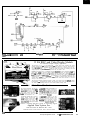
Figure 3b--An MC66HC11
processor oversees the
entire measurement
procars. Thepcessork
on-board memory and
petipfwak keep extemal
sllppcft a’rariby to an
ahdub minimum.
Only $851 for iceMASTER-PE
The world’s most innovative 8051 emulator is incredibly
affordable. Metolink’s unique Advanced Emulation Technology
(AET, potent pending) delivers the best possible emulator volue
for engineers, consultants and students.
AET is o revolutionary design architecture that provides more
features with 75% fewer components, smaller board space and
lower cost. Emulator and probe electronics are integrated in o
single package only 3” by 4”.
Metotink also delivers leading-edge customer service, including
o 30 day money bock guarantee, 10 day trial for qualified
customers, rentol plans and free technical support.
4 Up to 40 MHZ Operotion
y 64K Emulation Code Memory
& 64K Extemol Doto Memory
3 Performonce Analyzer
UI 1’28K Hardware Breakpoints
y Macro Cross Assembler
w 16K Trote Memory
& supports 8031/8032’s
d suppom 8xc751/8xc752’s
u Tronyrent Trace
PL Windowed User lntedote
w Serial link to Any PC
(View Trace While Executing)
& Reol Time & Nonintmsiie
d Symbolic 8 Source
Level Debug
emission-acceptance angle, a larger 50mm x 50-mm sensing area, and an
MC68HCll microcontroller unit
(MCU).
The entire measurement process
[refer to Figure 2) is requested by an
external robot controller to the smart
sensor. Once initiated, the MCU
controls and reads the sensor through a
three-line interface: CLR, CLK, and
DATA. The MCU then calculates the
center of the object inserted into the
square based on absence of light at
individual receiver elements in two
dimensions. The object position is
coded using 6 bits for each dimension.
Once a GO request is received, the
computer sequence is as follows [refer
to Figure 3 for the schematic): The
MCU resets UZl/U22, turning on the
pair D7 and Q7 and latching their
condition into the synchronous serial
peripheral interface (SPI) port. It then
sequences down the line along the
horizontal (x) axis to D32 and Q32,
storing each pair’s condition in onboard RAM in single-byte groups. The
scan continues in the y direction
without interruption to D72 and Q72.
Notice the reverse sequencing
process: 7, 6, 5, 4, 3, 2, 1, 0, 15, 14 ,... 39,
38, 37, 36, 35, 34, 33, 32, 47, 46 ,... 73,
72. This feature allows the highest to
the lowest pair to match with the MSB
to the LSB in on-board RAM and also
follows the high-to-low order SPI
format. Only one pair is energized at
any one time.
If any of the beams within these
80 pairs is obstructed, the output of
U26 will go high for the respective pair
according to the threshold set by Rl. A
high or low will be loaded into the SPI
port for all pairs blocked or unblocked,
respectively [9]. When the MCU
provides the stepping-clocking sequence for the final pair, one extra
count is clocked in order to deactivate
all pairs to lessen power drain during
idle time. Both sets of serialized
signals are read from on-board RAM,
and object position is calculated and
sent to the parallel/serial output.
d Buihdn Self-Test
Call today
THE SOFTWARE
for FREE DEMO
(800) METAICE (
Metdink Corprotion PO. Box 1329 Chandler, AZ 85244-l 329
Phone: (602) 9260797 FAX: 1602) 926-1198
See us al We Embedded Sysfems Conlerence-Booth #SO4
18
Issue #29 October/November, 1992
The Computer Applications Journal
,,@@$I
#ill
My MC68HC 11 configured with
pin PEO to ground and jumper Jl
allows RS-232 sensor-to-PC software
Listingl-A demonsfrationprogramshowswhaf'sinvolvedin
RELAY
INTERFACE
@i%BTSi)
dealing wifh b5eposifionsensor
*****
* 68HCll Register Equates
*****
PORTC
PORTB
DDRC
DDRD
SPCR
SPSR
SPDR
51003
$1004
$1007
$1009
$1028
$1029
S102A
EQU
EQU
EQU
EOU
EQU
EQU
EOU
*****
~C~NNECTS
* Buffalo 3.2 Eauates and Jump Table adr
*****
547
SFF7C
(0033-0047)
Warm start
ORG
so001
Lower half of RAM
RMB
RMB
RMB
RMB
RMB
RMB
RMB
RMB
RMB
RMB
1
1
1
1
UlO & U20
U9 & U19
U8 & U18
U7 & U17
U6 & U16
U5 & U15
U4 & U14
U3 & U13
U2 & U12
USTACK EOU
WARMST EQU
* RAM VARIABLES
*****
ORG
1
1
1
1
1
1
so100
Ul & Ull
~~-2325
A R - 1 6 R E L A Y INTERFACE . . . . . . . . . . . . . . . . . .._.... $89.9!
Two 6 channel relay output ports are rovided fw control o
up to 16 relays (expandable to 126 re Pays usmg EX-16
expansion cards). Each relay output port connects to a
relay card or terminal block. A variety of relay cards and
relays are stocked. Call for more info. RS-422 available
(distances to 4,poo feet). PS-4 port selector ma~ be used
to control satellde AR-16 inteffacas. (up to 16.3 4 relays)
RD-8 REED RELAY CARD (8 rel 9 10 VA . . . . . . . . . $49.9!
?I277 VAb ) . . . . . . . $69.9!
RH.8 RELAY CARD 10 amp SPD
EX-16 RELAY EXPAk SlON CARD (16 chsnnel)...S 59.91
*****
DA10
DA9
DA8
DA7
DA6
DA5
DA4
DA3
DA2
DA1
TO
ANALOG TO
DIGITAL
pairs
pairs
pairs
pairs
pairs
pairs
pairs
pairs
pairs
pairs
Upper half of RAM
(CONNECTS
TO
us-2323
A0c.16 A/D CONVERTER
*****
* START
*****
* Register Initialization
Init stack pointer
LDS
#USTACK
Zero B for counter
LDAB
#SO0
Set X as counter
LDX
#SOOOA
* SPI initialization
Prepare CLK/SCK hi
LDAA
#SO2
and CLR lo
PORTB
STAA
%%00000010
LDAA
SS*.SCK.MOSI.MISO.RxD-In.TxD-Out
STAA
DDRD
SPI on as slave,
#%01001100
LDAA
CPHA=l.CPOL=l
STAA
SPCR
Clear any
LDAA
SPSR
possible SPIF
LDAA
SPDR
l PBO is 74LS393's CLR. PBl is 74LS393's
* CLK and SCK for SPI.
l Initiate scan
First falling edge
LDAA
#SO1
of SCK indicates
STAA
PORTB
*
start of xfer
Scan initiated with
CLR
PORTB
*
D7/07 pair activation
Wait a while
WAIT1
JSR
D7/07's condition
LDAA
#SO2
xfered thru MOSI
STAA
PORTB
(16 channel, 6 bit)..s 99.95
Input temperature, voltage. amperage, preswre,energy
usage, energy demand, lght levels, joystick movement arx
a wide variety of other types of analog sign&. Inputs may
be expanded to 32 analog or 126 status tnputs using the
40-l 6 or ST-32 expansion cards. 112 relays may be
xtntrolled using EX-16 expansion cards. Analo in uts
vay be configured for temperature input using t%C
e E-6
:emperature Input conversion. RS-422 w&able. PS-4 port
selector may be used to connect satellite ADC-16
“telfaces (up to 4.096 anelog inpuW16,364 status inputs
md 14,336 relays). Call for info on 10 8 12 bit converters.
‘terminal block and cable sold separately)
ST-32 STATUS EXPANSlON CARD. . . . . . . . . . . . . . . . . . . . . . 3 79.95
“put on/off status of relays, switches, HVAC equipment.
hermostats, security devtces. smoke detectors and other
devices including keypads and binary coded outputs.
‘rovides 32 status inputs (opt0 isolators sold separately).
rE-6 TEMPERATURE INPUT CONVERSlON . . . . . . . . . $49.95
“dudes 8 temperature sensors 8 terminal block.
remperatoie ran e is minus 40 to 145 degrees F.
‘s4 PORT SE%CTOR (4 channels RS-422).......$79.95
Zuw?rts an RS-232
R Into 4 s&?ctabfe RS-422 ports.
10 CH TONE DEC&ER and other serial interfacing
)ro !ucts available Call for free informabon packet.
* FULL TECHNICAL SUPPORT...Pmvidcd wer the
telephone by our staff. EACH ORDER INCLUDES A
FREE DISK WITH PROGRAMMING EXAMPLES IN
BASIC, C AND ASSEMBLY LANGUAGE. A detailed
technical reference manual is also included.
- HIGH RELIABILITY...engineered for continuous 24
hour industrial applications. All ICs socketed.
- Use with IBM and compatibles, Tandy, A ple Mac and
most other computers with RS-232 or R d-46 ports.
All standard baud rates and protocols may be used
(50 to 19.200 baud).
Use our 600 number to order FREE INFORMATION
PACKET. Technical Information (614) 464.4470.
24 HOUR ORDER LINE (800) 842.7714
Visa-Mastercard-American Express-COD
International & Domestic FAX (614) 4649656
Use fcf information. technical support & orders
ELECTRON&? ENERGY CONTROL,
360 South Fifth Street, S&e 604
Cdumbus, Ohio 43215
INC .
w112
Thebmputer ApplicationsJournal
lrtus~Octo~dNove~r,1992
1 9
debugging and development with
Motorola’s BUFFALO program. Listing
1 provides a demonstration program
used to acquire and store data.
The code is implemented in the
MCU’s on-board RAM as a subroutine
while under control of the BUFFALO
program, with a warm start back into
BUFFALO after program execution
occurs. Again, acquired emitterreceiver pair data is displayed on a
PC’s screen from on-board RAM with
a BUFFALO command. The most
important software detail involves the
SCK and DATA timing. SCK (CLK)
speed is dependent on the
phototransistors’ rise and fall time.
Although SPI rates as high as 2.1
megabits per second are possible,
Siemens specifies the receiver with a 6
ps maximum rise and fall time. Still
yet, testing yielded 129 ps due to the
effect of coupling with the multiplexer, resulting in an optimum period
of 135 ps (7.41 kHz, which isn’t one of
the four selections in master mode).
SPI polarity and phase were initialized
for stepping on the falling edge of the
clock, and data latching on the rising
edge.
Calculating position requires
determining the nature of the data
from the arrays. Data is classified as
reliable or unreliable. Unreliable data
refers to noise (any pattern other than
one consecutive group of blocked
elements) or signal absence (all
elements unblocked or all elements
blocked), with appropriate codes
transmitted for each type of condition.
Reliable data is processed by a simple
algorithm to locate the object center.
As I noted earlier, the microcontroller uses six parallel bits per
dimension to code the calculated
object position within the array of the
sensor. In addition, raw position,
position codes, and error codes are sent
to the optional terminal for user
verification if desired. The 26-pin dualrow header on the circuit board
provides RS-232 interfacing when a 25
to 9-pin adapter is used. Nine of the 25
pins are used to avoid circuit contention with the parallel output on the
same header.
Eventually I will want robustness:
the ability to handle unreliable data. I
Listing l-continued
INCB
* Loop through scan
LPl
PORTB
CLR
JSR
WAIT1
LP2
LDAA
#SO2
STAA
PORTB
INCB
CMPB
BNE
LPl
CLR
PORTB
LP3
LDAA
SPSR
BPL
LP3
LDAA
SPDR
STAA
0.X
JSR
WAIT1
LDAB
#SO0
DEX
CPX
BNE
LP2
LDAA
#SOC
STAA
SPCR
JMP
WARMST
*
#a
#soooo
Record data count
Next pair activated
Wait a while
Next pair's condition xfered
Record data count
One byte yet?
No, go back for more
Yes, activate next pair
SPDR full with 1 byte?
Keep looking for flag
Load into on-board RAM
Wait a while
Reset data counter
Count down
All data in?
No, go back for more
Yes, SPI off. Resets/ends
transfer. And...
go back to Buffalo prompt '>'
* Subroutine
*
WAIT1
WAITlA
LDAA
SUBA
BNE
RTS
%530
a1
WAITlA
Counter
Count down
Finished?
x113
Issue #29 October/November, 1992
TheComputer ApplicationsJournal
hope to implement a form of fuzzy
logic in the future to deal with the
tendency of the data rather than rigid
rules of traditional logic [lo].
PERFORMANCE OF THE SENSOR
I conducted several tests to
determine operational limits of
accuracy, repeatability, and speed.
Tests showed a minimum of 0.22 mm
for object size measurements. Average
position measurement errors in the x
and y dimensions were 0.07 mm and 0
mm, respectively. Measurement time
was 11 ms (demonstration program).
Finally, the sensor had excellent
repeatability and a greatly reduced
power drain (including a single +5-volt
supply] compared to the first circuit.
The component cost was $476.76.
An insertion performance of over 98%
of cuttings is projected. The sensor has
added some other benefits as well. It
can detect the proper grasp of a cutting
by the robot before attempting insertion into the plug. Also, it has the
capability to abort a particular cutting
cycle if no object is detected. [51
1. W. I,. Whittaker, G. Turkiyya, M.
Herbert, “An architecture and two
cases in range-based modeling and
planning,” IEEE, 1987.
2. W. Simonton, “Automatic plant
handling and processing in a
robotic workcell,” Transactions of
the ASAE, 1990.
5. S. Ciarcia, “Why microcontrollers?“, BYTE, August 1988.
6. S. Ciarcia, B. Brown, “Using the
Motorola MC68HCll”, Circuit
Cellar INK, Issue 18, December/
January 1991.
7. M68HCll Reference Manual,
Motorola Inc., 1989.
3. W. Simonton, “Issues in robotic
system design for transplant
production systems,” Inteznational Symposium on Transplant
production Systems, Yokohama,
Japan, 1992.
8. Optoelectronics Data Book,
Siemens Components, Optoelectronics Division, 1990.
4. W. Simonton, B. Farmer, “Sensor
for two-dimensional position
measurement of small objects,”
Transactions of the ASAE, !992.
10. M. AbdelRahman, “Artificial
Intelligence expands sensor
applications”, Electrical Construction eJ Maintenance,
December 1991.
Brian Farmer was formerly an Electronics Engineer with the University
of Georgia Experiment Station and
occasionally does consulting through
Power Tech Inc. He is now a full-time
student in the University of
Arkansas’s Electrical Engineering
Graduate program with a teaching
assistantship.
9. S. Ciarcia, “Let your fingers do the
talking”, August 1978, BYTE.
My thanks to the clear thinking and
wise supervision of Dr. Ward
Simonton.
401 Very
Useful
402 Moderately Useful
403 Not Useful
Tw523
Power Line Interface
Developers Kit
Interface Your Computer To Transmit And
Receive X-10 Codes Over Your AC Power Line.
Two-Way Communication.
Real Time Environment Control.
DEAL brings together all of the tools used to develop software fol
jingle Board Computers (SBC) and blends them into a menu-driver
windowed environment that speeds your development process.
l
l
Kit Includes
‘IW523, Cable, Interface Connector (S/P)
Documentation. Source Code Supplied in
“c”, Pascal, BASIC or Run Time.
Disks 5.25in & 3.5in Format.
l
l
l
l
l
l
l
Baran-Harper Group Inc.
i
114
Voice (416) 294-6473 BBS (416) 471-6776
Fax (416) 471-3730
Automates the Compile-Assemble-Link-Download Cycle
Works with any Compiler, Assembler, Linker, etc.
Use the built-in Editor or link to your own Editor, it’s easy
Great for BASIC and FORTH interpreters too
Interrupt driven serial communications to the SBC
Swaps memory to make room for the largest tools
Resizable, Zoomable Windows for Editing, Browsing and
Target Communications
Fully integrated mouse and keyboard control
In use for 2 years at Major Universities and Corporations
Requires
pc’xT’AT w’5’2K
Demo Available on BBS
30 day Money-Back Guarantee
Phone (415) 494-2363
Compuserve: 74 156,1207
BIX: ecarryer
- ‘.0. Box 9524, Stanford, CA 94309 BBS (415) 494-8463
;__ c r e a t i v e
; applications
- , engineering,inc.
Wl
The Computer Appiications Journal
Issue #29 October/November, 1992
Brian Kenner
& John Wettroth
I he Ueslgn 0T a Ime
1
Domain Reflectometer
few years ago, a
friend of mine
needed a portable
network cable tester. He
does LAN management and found that
cable problems were the cause of a
very large number of network instabilities. I wasn’t surprised, having also
managed several large networks at one
point in my life. I had grown weary of
having a system fail whenever someone decided to rearrange the office and
inadvertently disconnected the
network while moving a computer.
Certainly, no replacement exists
for building networks with some level
of fault tolerance, but doing so is not
always physically possible or economically viable. The type of cable tester
my friend suggested was not going to
solve network errors originating from
the “designer office worker” anyway.
Nevertheless, my friend reasoned
that if a truly fault-tolerant network
wasn’t possible, providing the means
to quickly locate the cable fault was
the next best thing. He proposed I
build a network cable tester: a Time
Domain Reflectometer (TDR).
Our portable TDR is based on the
Intel 87C51 microcontroller. We
designed it primarily to measure the
22
Issue #29 OctobedNovomber, 1992
The Computer Applications Journal
length and termination impedance of
coaxial cables commonly used in
computer networks, such as Ethernet,
Arcnet, and so forth.
The TDR uses time domain
reflectometry techniques to measure
length and calculates the actual
termination impedance based on the
amplitude of the reflected waveform. It
has a measurement range of approximately 1800 feet and handles 50- and
75ohm characteristic impedance
cables (primarily RG-58 and RG-59
used in thin-wire networks).
The hardware combines an 87C5 1
microcontroller with a 4-line 20character LCD display, an infrared
three-key touch-screen interface, a
low-power PAL, a dual g-bit DAC, a
very high-speed comparator, and a
handful of digital and analog “jellybeans” to bring it all together.
The software consists of approximately 3K of 805 1 assembly language,
which includes a flexible menu
system, a custom integer math
package, and the actual measurement
code. A 9-volt battery powers the unit,
which features automatic shutoff, and
it is packaged in a 2” x 4” x 6” plastic
enclosure. We also kept the bill of
materials below $200.
THEORY OF TDRS
The TDR capitalizes on the
traveling waveform’s characteristic of
reflecting some portion of its power as
it passes through the interface of two
dissimilar materials. A detailed
understanding of why these reflections
occur requires more space than I have.
However, I will cover the theory
necessary to build the TDR, which
centers on how electromagnetic waves
propagate down a transmission line.
v+dv
V
I
--dVd,
I+dl
r
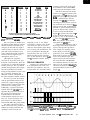
Flgun l-Some V&D/S and differenfial calculus help
show how the time domain rekctcmeter woks.
Transmission lines result from the
interaction of wire sections that make
up any circuit. In most cases, the
interaction between the wire in the
signal and return paths is insignificant
relative to the effect of the physical
components that form the system.
However, in the case of network
cabling, the distributed reactance (both
inductive and capacitive) is substantial
with respect to the data rates involved.
Figure 1 and some differential calculus
help show how these reactive elements sum.
In an infinitesimally small
element of the transmission line, dz,
voltage and current are defined by
V-(V+dV)=-dV=(Ldz)($)
and
-dI=(Cdz) (g)
where L is the series inductance and C
is the parallel capacitance of the cable
conductors measured in inductance
and capacitance per unit foot. If I
assume a lossless transmission line, I
can combine the above equations to
form a pair of linear differential
equations representing the variation of
voltage and current in the conductors
at position z. These equations are
-WL(~)
w-w
They have a solution of
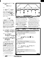
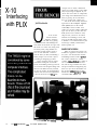
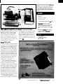
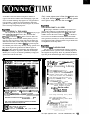
Photo l-The time domain rebctometer uses a 4-line by 2o-thracter display for ail operator input and ou@vL Sotf
keys and buch screen circuiby make for a vety flexible inkdce.
is the velocity of the electromagnetic
wave in the cable and is used to
compute the physical distance to the
discontinuity.
In a vacuum, the dielectric constant (E) and permeability (p) are equal
to 8.854 x lo-l2 F/m and 4~ x lO-‘H/m,
respectively, so the speed of propagation becomes c, or the speed of light.
Defining the equations for
capacitance and inductance per unit
length of the two most commonly
used types of cable is also helpful. For
coaxial conductors
V = F, (z, - vt) + Fz (z, + vt)
where v and z, must be
For parallel conductors
V=&
zc.=
c
$I;
and v play very important roles in
the TDR’s capability to make its
measurements. z, is the characteristic
impedance of the cable and is used to
determine the magnitude of the waveform (and possibly phase) reflected at
the interface of the two conductors.
The parameter v, defined as
z,
Using these equations, I can define
Z, in terms of the physical and electrical properties of the cable: parameter a, the diameter of the inner
conductor; b, the diameter of the outer
conductor in coaxial cables; and d, the
distance between conductors in
parallel wire cables. The equationfor a
coaxial conductor is
and for a parallel conductor is
ZO-& (~)“ln(~)
The TDR makes its basic measurement by injecting a pulse into the
cable and subsequently measuring the
amplitude and phase of any reflected
pulse. The reflected pulse’s amplitude
and phase indicate the impedance of
the new material. The time elapsed
between pulse injection and the
detection of the return pulse is then
used to compute the round-trip
distance to the cable discontinuity.
What may be obvious at this point
is if the pulse is not reflected, no
discontinuity exists in the cable. The
mystery is why any portion of the
wave reflects at all, and upon being
reflected, why the electromagnetic
wave may undergo a phase change.
Though the TDR’s injected pulse
is by no means sinusoidal, Fourier
analysis shows it is composed of
sinusoids. For the following discussion, it is easier to assume the traveling wave is purely sinusoidal and of
some particular frequency. If the
transmission line is terminated and
assumed to be lossless, then the load,
The Computer Applications Journal
Issue W29 OctobedNovember, 1992
23
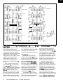
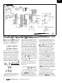
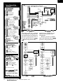
Flgun 2-An UC51 nms !hs TM. A 2-channsl DAC k used b contd he LCD dkp/ay conkasf and to aeats a vafiatie oflsel br the measurtnnent tit&s. The pwerconbol
tinxiby au&malical/y powtw Ihe system up al the prars of a tutbn and powers if down at& a bed p&d ofinacfitity.
Z,,, must also equal V/l of the incident
waveform. Thus, using the equation
developed for V and Z, the following
relationships can be established:
Don’t let the complex exponentials
distract you. They are, in conjunction
with the parameter A, part of the
characterization of the general sinusoid and will be divided out. What
remains is an equation relating the
complex amplitude of the incident
waveform to the load impedance, Z,,
and the characteristic impedance, Z,,.
waveform with predictable results. In
the limit, with Zo equal to zero, A’
equals -A and shows that the incident
waveform will be entirely reflected
with a 180” phase change. When the
load impedance is infinite, A’ equals
A, and the entire waveform reflects,
but this time without a phase change.
As long as the load impedance is
purely resistive and does not equal the
characteristic impedance exactly, the
reflected wave will have at least some
portion of its power reflected, with
either a 0” or a 180” phase change. Not
surprisingly, you will observe a phase
change other than 0” or 180” when the
load is reactive.
An understanding of how power
dissipates in the transmission line
explains why a portion of the wave
reflects at all.
Power= IV= g = v [+ L12 + i CV”)
This equation is the definitive
relationship for TDR. With it, you can
anticipate the reflection of any
24
laaue #29 October/November, 1992
Because the equations developed
in the preceding paragraphs are based
upon a lossless transmission line,
power dissipation only occurs by
transmitting power from one section
of the cable to the following section. It
The Computer Applications Journal
does not occur by the conversion of
electrical energy to heat energy as you
might expect in resistive circuits.
In fact, as I have shown, although
Z, is real, P represents the magnitude
of power passing any point on the
transmission line during a given
instant. As long as each subsequent
section of the transmission line has
the impedance Z,,, the waveform
continues to travel down the transmission line undisturbed; each section
passes energy to subsequent sections.
The specific F/Z0 changes upon
reaching a section of cable or termination resistance that does not have the
equivalent characteristic impedance.
Some portion of the power must be
either returned or reflected because a
diminished or increased magnitude of
power is transmitted to the new load.
The 0” or 180” phase is a consequence
of the increase or decrease in power
transmitted at that point.
Real-life transmission lines do not
behave strictly this way. At some
point, the cable length becomes
significant because the assumption
that cables are lossless is not valid. In
real cables, both the conductor and the
_
4 x 28
LCD D i s p l a y
Rejecting this reflection with
software is possible, but the noise
margin will be affected. Unfortunately,
some portion of the waveform’s power
also will return before it reaches the
cable fault, further reducing the
instrument’s usable range. Initially, we
thought this problem meant a reduction in supported cable types because
some form of internal termination was
required to perform the measurement.
In the end, we decided to cover the
two most common types of coaxial
cables with a very small relay, which
toggles the TDR’s internal termination
resistance between 50 and 75 ohms.
HARDWARE DESIGN
The electronics for the system
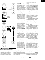
a ~IJC!I screen inferiace. Three pairs of LEDs and pho&tmsislotx
de&t a fingw poihting at one ol three choices displayed on the LCD display.
rlgun s-usermpur IO me run I
dielectrics have resistance. This
resistance not only affects the transmitted wave amplitude, but also
influences the phase relationships of
the frequency components in the
transmitted waveform. The TDR is
forced to consider this fact when
computating termination resistance.
Ultimately, this real-life effect limits
the length of cable the TDR can test.
HUMAN INTERFACE
We imagined how the TDR would
be used and attempted to build the
instrument around those purposes.
The TDR had to have a simple interface and a small package. Simply
stated, the number of basic actions
required to operate any instrument or
appliance should be as few as possible.
Because nearly anyone can memorize
three or four operations to perform
some function, we restricted the
number of keys on the TDR to three
and let the software handle the rest.
With the above goals in mind, we
decided to make a touch screen
interface. That would allow us to
26
Issue W29 October/November, 1992
present three “buttons” on the display
and let the operator select one with
the point of a finger. It also allows us
to add features later by simply changing the firmware.
For our design, the best combination of keys was two for moving
through menus and one for selecting
an option. We ensured that any function or operation in the TDR would be
compatible with the three-key interface, which unfortunately meant we
would have to anticipate any parameter that eventual users may wish to
enter and incorporate into the menu.
CABLE TYPES
Computer networks can and do
use a variety of cable types. Most of
them fall into two categories: coaxial
and twisted pair. Each category has its
own characteristic impedance. The
problem is TDR has its own intrinsic
characteristic impedance, which may
or may not match the cable under test,
so there may be reflections generated
at the interface of the TDR and the
cable under test.
The Computer Applications Journal
consist of two major parts: microcontroller and measurement. The microcontroller electronics include the LCD
display, DAC, and IR touch-screen
circuits. The measurement electronics
consist of a high-speed comparator, a
low-power latching relay, and a
discrete cable interface circuit.
The microcontroller is an 87C5 1
operating at 12 MHz (see Figure 2).
The microcontroller’s oscillator also
clocks the measurement PAL., U9. The
clock to the PAL is enabled and
disabled to save power when actual
measurements are not in progress.
The three data inputs for the PAL,
the LCD display, and dual DAC data
inputs populate the microprocessor’s
port 0. The DAC is the only device
actually addressed as a memory device
(i.e., using the MOVX instruction).
A single 9-volt battery powers the
TDR. Automatic power down is
accomplished with the aid of PMOS
FET Q3 and NPN transistor Q 12.
When the operator presses the
“on” switch Sl, the gate of Q3 is
pulled low, applying power to the
LM3 17 and subsequently tBe microcontroller. At power-up, all processor
port pins go high including Pl. 7,
which keeps Q3 and Q12 turned on.
To power down, the processor simply
drops PI. 7. The sum of the leakages of
Q3 and Q 12, which are extremely low
and comparable to the self-discharge
rate of the 9-volt battery, equals the
amount of standby current when the
system is off.
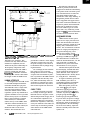
Fiiure 4-A// he noise-critica/ circuitry is wired on a daughterboard with a ground plane. The ZZCVIOZ PAL chip eliminates a handlul of circuitry.
Al7ENTION: BASIC-52, BASIC- 180 and BASIC-l 1 DEVELOPERS
Flnally. on advanced development environment for BASIC single-board computers.
BDTcomblnes all the tools you need-lncludlng fdlfor, Compllrr. D&uggw and
TerminaIemulator In 0 powerful. fast. easy-to-use. ond totoIly Integrated package.
Real-Time Multitasking Executive
l
HITACHI 6303 INTEL 80x88/x86,80x96,80x51
MOTOROLA 680x0, 683xx, 68HC11t68HC1 6
INMOS T400, T800 ZILOG Z80/2180
l
l
l
l
l
l
l
-
l
. Written in C
Preemptive Scheduling
* Source Code included
Fixed or Dynamic Priorities
* No Royalties
Timeout on some services
* Technical Support
Configurable and ROMable
Broad C Compiler Support
lntertask Communications
Sensible License Agreement
-Messages
Most Popular C Compilers
-Queues
-Semaphores
supported
Memory Management
Resource Manager
Over 50 Executive Services Available
System Level Debugging Utility
System Generation Utility
450 Page User Manual
l
l
l
l
Editor
. Configurable keystrokes and colors . Memory resldenf text (FAST0
. Block move/copy/delete/read/write . Find % replace * Auto-Indent
Compiler
. Structured proooromr: DO/UNr/l. WHILE/WEND. BEGIN/END . No line numbers
. Up to ZO-char&3 vorloble and lobei”DmeS . S”b;o”tlne LOCAL vorlables
. Five types of commenfr Ilncludlng multlllne) stripped during download
Debugger
. UP lo 1000 BREAK/PASSpolnts .
PROFILE . Up to 40 WATCH vorlobles
. Integer vorlobles WATCHable 0s DEC/HEX/BIN . A,,, 0, portk,,, aroy WATCH
Execuilon
Terminal
l
Editor. file. and compile buffer download to SBC a FNe capture from SBC
Host PC Requirements
. 5 12K . One disk drive . One serial port . Mono,C/E/V/GA . DOS 3.x-5.0
l
l
l
l
l
One Time License Fee From $995
Discounts for Multiple Licenses/Ports
The only real-time kernel you’ll ever neeP
lndlvlduol verslons are avaIlable for BASIC-52 (BD751). BASIC-180 (BDrlBO) and
BASIC-l I (BDTII) SEX3 0 SlW. SPfClAl OFFER--‘BDT-PM’ combiner all three
verslo”~ 0 $489 for a soyln~s of over SlOO. Order today-offer expires soon...
40944 Coscodo Place . Fremont. Collfornla 94539 (510) 557-0264 . FAX (510) 657-5441 . BBS (510) 657-5442 lza@al
Phone 800/525-4302 or 7131728-9688
#119
See us at the Embedded Systems Conferenck-B~~th #836
27
Issue #29 October/November, 1992
The Computer Applications Journal
THE LCD
The LCD display is a standard 4line by 2Ocharacter module [Figure 3).
The menu program uses the top two
lines to display measurement data and
menu information, and it uses the last
two lines to display soft-key data for
the touch-screen keyboard.
DAC A of U3 provides LCD
contrast control VEE through op-amp
follower U4c. The DAC voltage
reference is provided by D4, a
micropower 1.25volt bandgap reference. The reference is buffered by opamp follower U4a and also provides a
2.5volt reference to the measurement
circuit through amplifier U4b.
TOUCH-SCREEN LED CIRCUITRY
An infrared light across the face of
the display, in a configuration where
the operator’s fingers interrupt it,
implements the touch-screen display.
Dl, D2, and D3 provide the IR
light to phototransistors Q3, Q4, and
Q5, respectively. Transistors Q8
through QlO drive the LEDs at 70 mA
for brief periods of time. P1.0, P1.l,
and PI.2 provide the control signals
through resistors R25, R26, and R27.
The phototransistors operate at
low gains using small collector loads
of 1 k to minimize ambient light
swamping further. The transistors are
AC coupled to transistor switches Q14
through Q15 by a differentiating
network consisting of Cl3 and R28
through Cl 1 and R30, respectively.
These transistors provide microcontroller input P1.3, P1.4, and P1 S.
When an LED is turned on, its
respective phototransistor conducts
about 2 mA with a fast falling edge.
Differentiating capacitors pass this fast
edge with a time constant of 50 ps.
The pulse turns off the NPN transistor, producing a SO-us high on the
processor’s input for each falling edge
on its LED. The software samples the
phototransistor outputs briefly after it
turns on an LED. If it sees a high
input, then the light from the LED
must be reaching the phototransistor,
so a “key” must not be pressed.
MEASUREMENT ELECTRONICS
The maximum resolution in
Listing l--The 7DR PALis ddlinedusingahigh-/eveldssaiplionfo/etUlecompiler makehsfferuseofthe
par-~ andbreducelhe number ofoutputs.
,*******f*t******************************~~~~~~~*~~~~~~~~~*~~~~~,
/*
/* TIME DOMAIN REFLECTOMETER PAL
/*
/* It does the following:
/*
6 bit programmable down ctr. Id in two l/Z's, ldth.ldtl
/*
zr_ct goes high at zero
/*
synchronizes go output falling edge of go in and clock
/*
multiplexes dallas delay generator on inputs
/*
/******************
TDR (in clk.iZ..O.l dtl.ldth.go.zr.zr20,zr4O,zr6O,.zr8O; I* inputs */
out dlout;
reg ct5..0 sg.zr_ct)
/* registered outs */
'* define relationships- begin */
* _________________
*/
/* define groups
,f -...____..._____.
group
group
group
group
i[iZ..OI;
ct[ct5..0]:
mux[iZ..OI;
d[zr80.zr60.zr40.zr2O.zrl:
/* clocks
,* _________________
sg.ck = elk:
zr_ct.ck = elk;
ct[I.ck = elk;
/* do output enables
,* _________
sg.oe = 1:
zr_ct.oe = 1
dlout.oe = 1
ct5.oe = 1:
ct4.oe = 1;
ct3.oe = 1;
ct2.oe = 1:
ctl.oe = 1:
ctO.oe = 1:
IssueX29 October/November,1992
*/
*/
*/
*/
*/
*/
/* have to do this to get feedback */
/* do aclr and spre
*/
/* ___________._____
*/
sg.aclr = 0;
zr_ct.aclr = 0:
sg.pre = 0;
zr_ct.pre = 0;
ct[I.aclr = 0:
ct[l.pre = 0;
/* define mux action, load low and high and count */
,* _.._____.______._
*I
dlout = d[mux[II:
/* mux high level construct
if (go==11 {
/* if go high wait for load or hang l
if (ldtl==l && ldth==l)( /* if both loads high just stay here
sg = 0:
/* sync go = 0. no pulse
/* zr_ct=O. input to delay line
zr_ct = 0;
ct[l = ct[l:
i* don't decrement counter- hang
I
else (
if (ldtl==O)
{
*/
/
*/
*/
*/
*/
/* if one or more loads are low then */
/* if load low. load in to low ct
*/
(continued)
termination resistance is limited by
28
*/
*/
*/
*/
*/
*/
*/
*/
TheComputer Applications Journal
the minimum signal-to-noise ratio, so
critical portions of the measurement
circuits are located on a small, very
tightly hand-wired daughter board (see
Figure 4) with a ground plane. These
key circuits include the termination
relay, the comparator, and the D flipflop. The logic board contains the lesscritical portions of the measurement
circuit.
The heart of the measurement
circuit is U9, a low-power, high-speed
PAL device (ICT 22CVlOZ). It reduces
the chip count by as much as four MS1
logic devices and makes fitting all the
electronics into a small package
possible. This device orchestrates all
the high-speed operations and timing
done by the system. Listing 1 presents
the PAL’s defining code.
Outputting a time delay to the
PAL begins a measurement. The PAL
includes a &bit presettable down
counter, an B-to-1 digital multiplexer,
and a synchronizer circuit. Only five of
the eight multiplexer inputs are used,
and they are connected to the delay
line chip U8.
The input to the delay line is the
zero output of the 6-bit counter
(ZR_CT). The counter is clocked at 12
MHz (83.3-ns period) and followed by a
selectable multiplexer delay of 0,20,
40,60, or 80 ns to produce the delay
output. The PAL operates through
three data inputs that have multiple
uses, depending on the state of three
other inputs: load high (LDTH), load
low (LDTL), and Go (GO).
When LDTH goes low, the PAL
preloads the three high bits of the
counter. LDTL performs a similar
function for the three low bits of the
counter. The static value left on the
three inputs selects the multiplexer
routing. Note that the zero delay
output (ZR_CT) comes out of the PAL
and back into the PAL multiplexer
zero delay input (ZR). Logically, the
PAL could do this routing internally,
but having it do so would skew the
propagation delay for the zero delay
output.
The microprocessor brings the
PAL GO input low to begin a measurement. This signal is synchronized in
the PAL with the next clock edge to
output a synchronous GO output (SG).
30
Issue 129 October/November, 1992
Listing l-confinuep’
ct5
ct4
ct3
ct2
ctl
ct0
=
=
=
=
=
=
ct5:
ct4;
ct3
i2:
il;
i0:
/* leave high bits alone
1
if (ldth==O
ct5 = i2;
ct4 = il;
ct3 = i0:
ct2 = ct2:
ctl = ctl:
cto = cto:
*/
/* if load high. load in to high ct */
/* leave high bits alone
*/
t
1
I
else
t
i f (ctCl>O)
sg = 1:
ctCl--;
/*
/*
/*
/*
/*
(
if
(ct[l==l)
zr_ct = 1;
else
zr_ct = 0:
else
if
go is low- let's jam
if still count loop decrementing
put out sync go on first clock
decrement counter
on last count bring zr_ct high
*/
*/
*/
*/
*/
/* else zr_ct is low- to delay line */
I
(go==O) 1
zr_ct = 1;
/* if at zero then keep zr_ct 1
/* leave count and sg at I
ct[l = ct[l;
sg = I:
*/
"I
1
1
/* put part definition */
,* _________________
*/
putpart('P22CVlOZ'.'tdr'.
/*
8
9
10
11 12
5
6 7
1 2 3 4
clk.i0.il.i2.ldtl.ldth.go,zr20.zr60.zr4O,zr8O~GND.
*/
/*
14
15 16 17 18 19 20 21
13
zr.zr_ct.dlout.ctO.ctl.ct2.ct3.ct4.ct5.
*/
22 23 24
_, sg.VCC)
I* end of definitions *I
/* end of module
*/
1
The rising edge of SG is applied to the
glitch monostable circuit formed by
NAND gates U6a and U6b. The output
of this circuit goes low for about 8 ns
on the rising edge of SG. This pulse
drives the base of Q4.
When Q4’s base is pulled low, it
generates the very fast pulse at the
BNC test cable output. C6 fixes the
high-level output impedance of the
TDR at a very low value. Once Q4 is
turned off, the setting of latching relay
Kl and the parallel combination of R8,
R9, and R3 1 determine the impedance
TheComputerApplicationsJoumal
the line sees. This impedance is either
50 ohms or 75 ohms depending on the
setting of Kl.
Note that Kl is a permanentmagnet latching relay briefly pulsed by
the microprocessor to change state
through Ql and Q2, although it draws
no quiescent power.
The output connector is also
capacitively coupled to U5, an LT1016
[a very high-speed comparator). This
device has a propagation delay of 7 ns
and specifically operates on a single
supply. The comparator does have a
limited common mode range of 1.253.5 volts when run on 5 volts.
To push the signal into this range,
the positive input is biased to 2.5 volts
by doubling the voltage reference,
which brings it to the approximate
center of the common mode range.
DAC B and amplifier U4d provide the
negative input to the comparator. The
range of this input is O-3.95 volts. The
DAC resolution is about 16 mV for
measuring the height of the returned
waveform.
The comparator has complementary outputs connected to the clock
inputs of U7a and U7b. Two flip-flops
eliminate the pulse-width uncertainty
associated with measuring negative
returning pulses. The microprocessor
samples the flip-flops’ outputs at the
end of a trial measurement at P2.0 and
P2.1.
The PAL’s LDTL input clears the
flip-flops at the beginning of a trial
measurement. They are set after the
return of a pulse if the D input
provided by DL_OUT is present before
the comparator senses the pulse.
The measurement circuit operates
by injecting an extremely brief pulse
[about 10 ns) onto the cable under test.
This pulse travels down the cable and
reflects from any discontinuities
(changes in impedance) in the cable.
These reflections return to the TDR
and are captured by a very fast comparator, which clocks a D flip-flop.
A precisely delayed signal derived
from the original output provides the
D flip-flop’s input. The PAL generates
the delay, and a microprocessor can
vary the delay line from 0 to 5.5 ps in
2O-ns steps. This time resolution leads
to a distance resolution of 6 feet for
typical cable types and a maximum
cable length of 1700 feet.
TERMINATION RESISTANCE
Pulse amplitude measurements
are made by adjusting the threshold of
the comparator using a DAC until
return pulses are no longer seen. The
reflection coefficient is calculated by
comparing the transmitted pulse
height with the returned pulse height.
If you assume the cable is lossless,
then calculate the termination
resistance using the previously derived
formula
z,==zc.~I-VJv.)/~I +VJv.)
Assuming a cable is lossless does
simplify matters, but it leads to large
errors in the calculation of termination
resistance for long cables. The actual
attenuation coefficient per 100 feet
depends on cable type and quality.
Several standard nomographs are
typically used by engineers for correcting reflection coefficient for line loss.
The TDR handles this problem by
first determining the cable’s length
and the uncorrected reflection coefficient using the algorithm I’ve described. It then corrects the reflection
coefficient for line loss based on the
measured length before using the
injected pulse amplitude in the
previgus equation.
The voltage attenuation constants
for RG-58 and RG-59 are stored in
firmware. They are approximately 3%
per 100 feet of length for both RG-58
DOS Where You Want It
-Runs on Disk, ROM, FLASH
Develop your programs
ROM with ROM-DOS,
‘II@ irk Mlidespread use on a variety of
platfkm,
ROM-DOS has prm’en its deperrdahility.
on a standard PC and run them in
the flexible, affordable operating
system that was designed for embedded applications. Compatible with MS-DOS 3.3 1, ROM-DOS boots and runs from
ROM, disk, or FLASH memory. Features include: small size
(low as 36K); runs executable files from ROM; FLASH disk
support; remote disk and multimedia support; and a powerful
utility suite. Confirmed compatible by VeriTest, an independent evaluator, ROM-DOS is already in widespread use on
multiple system types. Developers Kit-which contains all the
tools and utilities needed to configure ROM-DOS to your
system, and includes license for 20 copies-costs only $495.
ROM-DOS royalty fees depend on quantity purchased, and
range from $3 to $25 per copy.
Free Demo Disk! Call Today Toll-Free l-800-221-6630
17455 68th Ave NE, Suite 304, Bothell, WA 98011, USA 206-486-8086
l
The Computer Applications Journal
l
fax 206-486-0253
Issue X29 October/November, 1992
31
and RG-59. Unfortunately, the
attenuation is not linear. Though the
TDR makes this simplification, it is
able to compute termination resistances accurate to about fl% for
cables up to 100 feet. The accuracy of
the termination resistance readout gets
worse from here because the attenuation effect was empirically characterized out to 1700 feet. It is probably in
the 10% range.
SOFTWARE DESIGN
The software for the TDR is very
simple and straightforward with the
exception of the menu system and the
integer math package. We used the
menu system to make the TDR easy to
use and to permit some reasonable
level of expansion and improvement.
The integer math package affords some
computational capability, but keeps
code size within the constraints of the
4K maximum of 87CSl.
The goal of the menu system is to
provide a b-treelike structure through
which menus and submenus can be
called for and returned to in a straightforward fashion. We wanted to add,
move, and remove menus and processes with ease. For the most part, we
were successful.
Each menu item is defined within
a menu structure. This structure may
have an unlimited number of items
and is terminated by a null. Each
menu item consists of three words.
The first word is a pointer to the
item’s display menu string. The
second word has the address to jump
to if that menu item is selected. The
last word is defined only when a
submenu is to be loaded, in which case
it holds the pointer to the submenu’s
data structure.
The menu system needed several
routines to manipulate the data
structure to operate. N XTMN U is a
function created to load a submenu. It
saves the calling menu’s address in a
parent menu stack, then it loads DPTR
with a pointer to the new menu
structure.
The function LASTMNU recovers
the parent menu’s table address and
places that value into DPTR. UPDATE_
M EN U scrolls menu items through the
display. P RI NT-M EN U updates the
32
Issue #29
OctobedNovember, 1992
Listing 2-The bud, screen allows easy changes and addibons & the menu& system.
: Main Menu Strings & Prompts
._.__________________________
~AINMNU: DB
I***** MAIN MENU ****',OH
TESTCBL: DB
'1. Test Cable
'.OH
TESTTYP: DB
'2. Set Test Type
'.OH
CBLTYP: DB
'3. Set Cable Type
',OH
SHW_PAR: DB
'4. Show Setup
'.OH
ADJDSP: DB
'5. Adjust Display
'.OH
;
;data structure for main menu
AMENU:
D W
MAINMNU
:test cable
DW
TESTCBL
DW
RUN
DW
OH
;test type
DW
TESTTYP
DW
NXTMNU
DW
TTMENU
:cable type
DW
CBLTYP
DW
NXTMNU
DW
CMENU
:show parameters
DW
SHW_PAR
ow
SETUP
OW
OH
:adjust display
DW
ADJDSP
DW
NXTMNU
ow
ALMENU
:end of main menu- zero
OW
OH
; PTR to main menu string
: PTR to function title
: PTR to function routine
: No data this time
: PTR to submenu title
: PTR to Nextmenu program
; PTR to submenu data structure
: PTR to submenu title
: PTR to Nextmenu program
: PTR to submenu data structure
: PTR to submenu title
; PTR to Nextmenu program
; PTR to submenu data structure
; PTR to submenu title
; PTR to Nextmenu program
: PTR to submenu data structure
: nul establishes end of structure
: end of data structures for main menu
._____________________.-_______________-_-_______--_______---_
I NXTMNU: A task that saves the current value in DPTR
and reloads DPTR with a new menu structure.
Registers used
DPTR:
ACC:
B(FO):
OH:
/XTMNU:
PUSH
PUSH
PUSH
MOV
RL
ADD
MOV
MOV
INC
MOV
INC
MOV
ADD
RL
MOV
MOVC
PUSH
TheComputerApplicationsJoumal
Loaded with new menu table address
Scratch register
Scratch register
Scratch register
ACC
OFOH
OH
A.MENUPTR
A
A.tMNUSTCK
R0.A
@RO.DPH
RO
@RO.DPL
MENUPTR
A.OPPTR
A.#MDATA
A
B.A
A.@A+DPTR
ACC
: B register
RO
; This section of code gets the
:
:
pointer to the menu stack,
saves the current OPTR in
the menu stack, and
the menu increments
stack pointer
;
:
: This section of code uses the
:
current menu table to obtain
the submenu table address.
:
:
:
It then loads that ad'dress
into DPTR.
[CfMtiWf?d)
leap in functionality would be to make
the TDR, or something like it, a more
integrated part of a network. It could
be a device that resides semipassively
on the network and is occasionally
polled by a PC via an RS-232 connection. Use your imagination. q
Listing 2-cofltiued
MOV
INC
MOVC
MOV
POP
A.B
A
A,@A+DPTR
DPL.A
DPH
;
: Once a new table has been
; to be repainted.
SETB
SETB
MOV
INC
INC
POP
POP
POP
RET
DISPFLAG
TTLEFLAG
OPPTR.#OH
DPTR
DPTR
OH
OFOH
ACC
loaded, schedule the screen
Brian Kennez is a project engineer at
Science Applications in San Diego,
Calif. He has developed several fixed
and hand-held microcontroller-based
instruments used in vibration and
radiation monitoring and analysis.
: Set "print option' flag
: Set "print title' flag
; Reset pointer to top of menu
Point to the first item
in the table.
display with the currently selected
menu. Listing 2 is an excerpt from the
TDR’s code.
A small collection of functions
that operate on 32-bit variables
performs all math on the TDR. The
TDR needed only an addition, subtraction, multiplication, and division
function.
THE COMPLEAT TDR
The instrument we’ve described
works in its most basic form, but we
think there is plenty of room for
improvement before any reasonable
production could be considered. It
would be fun to extend the number of
cable types supported and maybe even
add optical cable support. The biggest
John Wettzoth is employed as the
Chief Engineer of Science Applications’ Military Products Division in
San Diego, Calif. He also owns
Tzavtech, a sole proprietorship
involved in electronic instrumentation
development and HP-48 calculator
data acquisition.
404 Very Useful
405 Moderately Useful
406 Not Useful
ROM Borland or Microsoft C
Complete 80x86 ROM development kit!
Whether you use Borland C or Microsoft C to develop for
ROM, C_thru ROM will help speed your projects to
completion This complete ROM development package is the
only product that gives you all the tools you need for easy
development of 80x86 ROM code on your PC. C_thru_ROM
includes: ROMable startup code; floating point support; a
ROMable library that includes p-intf, malloc,@ee, etc.; and a
full 80x86 locator that outputs binary, Intel OMF, and hex
formats. You can debug with your Turbo debugger or use
Datalight’s remote debugger. Either debugger will work
through an available UART or ROM socket UARTs. This
comprehensive ROM development package is available for
only $495. Call, write or fax today for your free demo disk
and full details about C- thru-ROM.
Free Demo Disk! Call Today Toll-Free l-800-221-6630
I
1745.5 68th Ave NE, Suite 304, Bothell, WA 98011, USA 206-486-8086 fax 206-486-0253
l
The Computer Applications Journal
l
lssueX29October/November,1992
3 3
Serial l/O
on the
IBM PC
THE SERCOM SERIAL I/O
PACKAGE
Jim Schimpf
various devices to
an IBM PC or compatvery common, and done so with
everything from a manufacturer’s
microprocessor development board to
your latest widget. The serial interface
is extremely convenient, requiring
only a few wires and usually stretching
far enough to make “remote control”
mean something. The PC has the
hardware to make this task easy, but
the standard BIOS for IBM and clone
PCs does not support anything but
polling-type I/O, which means you are
guaranteed to drop characters unless
you use low data rates.
A large number of software I/O
libraries are available that can make
the PC serial I/O live up to its hardware. These libraries are all very good,
but if you are like me and have more
time than money, the simple fullduplex serial I/O package I describe
here is all you need to make your
project hum.
The code for SERCOM is written in
Microsoft Quick C and can be easily
added to your program. It can open
multiple serial channels [your hardware limits the number] and each
channel supports full duplex with ring
buffers on both input and output.
Various status checkers are present, so
your program can monitor the arrival
of each character or only be notified
when a complete line is received. This
way, even a program running on a slow
8088 can monitor two 9600-bps
channels. Also included is a sample
terminal emulator designed to talk to a
popular microprocessor development
board.
34
Issue 129 OctokdNovmber, 1992
The Computer Applications Journal
S ERCOM has ring buffers on both
input and output, which means the
program using the serial input does not
have to monitor the serial I/O line
constantly. This arrangement is a
major failing of the polling BIOS serial
I/O. If your program is busy doing
something else when a burst of
characters arrives, you will get only a
few characters and the rest will be
dropped. The solution to this polling
problem is to lower the data rate so the
program will be able to check the line
before another character can arrive.
Using SERCOM routines is like
using the file operations of s t d i o . h.
In this case, you include the header file
SERCOM . H in all the modules of your
program that you want to use the
serial I/O routines. Listing 1 shows a
skeleton for serial I/O.
Again like file operations, these
routines let you have more than one
open at a time. The supplied version of
S ERCOM limits you to two because
standard PCs only support two ports. If
you want to open more than two ports
at a time, you will have to add their
register and interrupt locations. You
may open as many ports as you have
hardware.
Table 1 shows the functions
available when the port is opened.
What each function does is obvious,
but the comments in the S ERCOM . C
program source code provide descriptions of them.
Table 1 also shows a number of
functions used a little less often. If you
start your serial I/O program on the
PC, then connect it to your remote
system; plugging in the cables will
probably generate a few garbage
characters. In a case like this example,
a call to cl ean_ser( 1 ensures the
input buffer is empty.
MTERM: A DEMONSTRATION
PROGRAM
Included with the source code is a
simple terminal emulator program
called MT E RM. I developed this program
to talk to the Motorola EVM board and
also included the capability to download S19 files to it.
Listing 1-A skelebn C pugram shows how a serial port is defined, opened, and closed.
#include <stdio.h>
#include <bios.h>
#include 'serc0m.h'
#define SREG(x)
((unsigned)
((unsigned)x + c->com_base))
main()
I
82509, they are accessed in the same
way.
To make the use of the device
registers clearer, I added the simple
macro
COM *ser:
/* Open the serial I/O port using COMl. 9600 bps, 8 data bits,
no paPity. a lOOO-byte input buffer, and a loo-byte output
buffer. */
ser = ser_init(P0RT_A.BAUD_9600,1000.100~:
if (ser == NULL) {
exit(-1); /* Flag error, port not opened */
1
that generates the address of the device
registers. This way, because c - >
c om_b a se is defined in the program
context, the address of any device
register is simply its offset (the
#de f i n ed value) plus the base. So you
will see things like
/* Insert main program here */
val = inp(SREG(LCR));
/* Close the serial port. Failure to do this means the machine
must be rebooted before the next program run. */
ser_close(ser);
1
Writing a terminal emulator using
the functions in S ERCOM is simple. At
the heart is a loop that monitors the
PC keyboard [using ks t a t ( I] and the
serial I/O line [using se r t s t ( 11. If a
character is seen on the keyboard, it is
read and sent to the serial port. If one
is seen on the serial port, it is read and
sent to the PC screen. When a key is
typed on the PC keyboard, the remote
serial device must echo it before it
appears on the screen.
MTERM can both capture received
data and transfer files. The program
easily sends all the received data to
and from a file just like it came from
the keyboard.
of these are the constants for the serial
I/O channels. They give the address of
the controller, the interrupt it is using,
and the EOI command. This last
command tells the 8259 interrupt
controller in the system that the
interrupt is handled. Other #def i nes
give the names of the various registers
in the serial I/O chip and the interrupt
controller.
Where did all these values come
from? Easiest are the serial device
registers. In original IBM PCs, the the
serial chip used was an Intel 8250.
While most modern clone PCs use
highly integrated chips that include
the serial ports instead of individual
SERCOM INTERNALS
I
MostofthecodeinSERCOM.Cis
very simple, but two areas deserve
further explanation: initialization and
ring buffers. The initialization [and
shutdown) code manipulates a whole
range of hardware registers in the
serial I/O chip and interrupt controller
of the PC. Ring buffers are a useful
concept, and if you haven’t used them
in your code you should try them.
INITIALIZATION
At the start of the SERCOM code
are a large number of #def i nes. Some
This code reads the L C R register
using S R E G to generate the address and
the i n p function to read this address.
With this step out of the way, you
can look further into initialization.
The first step is to set the data rate,
parity, and number of bits per word.
To do so, I used the Quick C function
_bios_serialcomO. Usingthis
function was simpler than actually
setting the bits in the registers. If your
C does not have it, writing an equivalent function is quite easy using the
data sheet.
The ring buffers are allocated in
the next step. Using the C memory
allocation functions allows you to
have variable-size buffers, and to have
them created when you initialize the
serial I/O port. This feature makes the
SERCOM package more general. How
these ring buffers work and are used is
detailed in the next section.
BOOLEAN putser(char ch, COM*c)
Output a character
int putsers(char*str, COWc)
Output a string
int getser(COM’c)
Get a character
int getsers(COM’c, int len, char’str)
Get a string
BOOLEAN serhit(COM’c)
Check for a character present in the
input buffer
BOOLEAN serline(COM’c)
Test for NEWLINE-terminated string in
the input buffer
clean_ser(COM’c)
Clear the input buffer
ser_dtr(COM’c)
Control DTR output
ser_cts(COM’c)
Control CTS output
Tabb l-The SERCOM package contains a vety bask set of&al
TheComputerApplicalionsJournal
poti access
hcfions.
Issue 129 October/November, 1992
35
Finally, you have to do the most
complicated and delicate operation in
the initialization: the setup of the
interrupt vector and enabling serial
intenupts. Carefully complete this
step’s actions in the proper order
because you are changing values inside
the operating system. The actions
done here are
1. Save the old interrupt vectors.
2. Insert the new ones.
3. Notify the interrupt controller
(8259) that interrupts are on.
4. Turn on the serial I/O interrupts.
All the code to do steps #l
through #4 is in the routine s e r_
i n i t 0 ( 1. Separate sections in this
routine handle the setup of COMl and
COM2. These sections set the unique
constants in the COM data structure
and set the different interrupt vectors.
If you add another port, you will have
to rewrite this routine, adding sections
to support your hardware. Listing 2
shows the code to do all four steps.
Note that you must turn the interrupts
off before you do anything. This way,
you won’t be changing a vector while
the system processor is trying to use it.
The interrupts are turned off and the
vectors are defined by Quick C; other
C compilers will have similar but
different conventions. Steps #3 and #4
are then completed, and the interrupts
are turned back on.
In the above section, notice that
you turned on the interrupts for serial
input but not for serial output. This
omission was made simply because
there isn’t any data to output yet; thus,
the 8250 transmit buffer is empty. The
8250 is set to generate a transmit
interrupt on an empty transmit buffer,
so that is not what you want now. The
code to transmit data [putsert 11
turns on the interrupt whenever new
data is to be sent and turns the
interrupt off when there is no more.
Shutting down the serial I/O
system is just the reverse of starting it.
The most important functions are
turning off the serial interrupt and
removing and restoring the original
interrupt vectors. If you don’t complete these steps, then a random serial
interrupt after your program finishes
will use the wrong vectors and cause a
system crash.
RING BUFFERS
Each serial port opened by SERCOM
is assigned its own set of receive and
transmit buffers (see Figure 1). Looking
Llsling 2-Ww he serial infempfs into he system and set@ up he 8250 must be done pupe@ to
avoid a sysfem crash.
/* Set the interrupt vector for COMl */
_disableO;
/* Read old interrupt and set new one */
corn1 = c;
c->old =_dos_getvect(c->int_number);
_dos_setvect(c->int_number.
int_serl):
break:
/* Enable IRO4/COMl. IRO3/COM2 on 8259 interrupt controller */
val = inp(INTC_MASK):
val &= c->irq_mask:
outp(INTC_MASK. val):
I* 8250 hardware setup *I
val = inp(SREG(LSR)):
val = inp(SREG(RBR)):
val = inp(SREG(LCR)):
val &= Ox7F:
outp(SREG(LCR). val):
outp(SREG(IER).l):
outp(SREG(MCR).OxB):
/* Read and discard status *f
/* Read and discard data *I
/* Rst DLAB for IER access */
/* OlllllllB */
/* Enable Data Ready INT*/
/* Enable OUT2. RTS. and DTR */
/* All done, restore interrupts to processor */
_enableO;
36
Issue629 October/November,1992 TheComputerApplicationsJoumal
incorrectly, they can bring a whole
system down due to an unreliable
serial port. Taking some time up front
to ensure solid serial port operation
will certainly pay off later. q
I want to thank C. J. Dunford for the
original code to DUMBTERM, a
simple terminal emulator.
Figun 1-A ring bufftu uses a pai? of pointers to keep back of the beginning and the end of Ihe buffer.
at the receive channel, you will see
that the head pointer stores a character
each time the hardware generates a
received character interrupt. The
character will be read from the
hardware, inserted into the ring buffer
at the head pointer location, and the
pointer is advanced. The entire process
happens in the background.
You can then get one character
from the buffer by a SERCOM call. The
character is taken from the tail pointer
location, and the tail pointer is
advanced. Each time a character is
added to buffer, the head pointer is
advanced. If the pointer hits the
physical end of the buffer, it is reset to
the start (which is where the ring in
Jim Schimpf works for an instrumentation firm designing hardware and
software for highway measuring
instruments.
the ring buffer comes from). When the
head and tail pointers point to the
same location in the buffer, it is either
full or empty. The program keeps a
count of the number of characters in
the buffer at all times, so distinguishing between full and empty is easy.
The ring output buffer is run the same
way except the noninterrupt part of
the program puts in characters at the
head pointer and the interrupt driven
output removes them at the tail
pointer.
Software for this article is available from the Circuit Cellar BBS
and on Software On Disk for this
issue. Please see the end of
“ConnecTime” in this issue for
downloading and ordering information.
TIME UP FRONT
407 Very Useful
408 Moderately Useful
409 Not Useful
Serial support routines may seem
like a small matter in the scope of a
much larger program. However, done
Best Price/Performance
In-Circuit Emulators
HARDWARE
r,orx,,ioix
I” <
mui,
I
rmulnler
Check out our complete line of DSP boards based on powerful
floating-point processors like the AT&T DSP32c (25 MFlops)
and the Analog Devices ADSP-21020 (75 MFlops). Several
analog interface modules are available. DSP boards start at just
$995.
E
SOLUTIONS
Call our friendly, knowledgeable staff to discuss your
applications and we’ll show you how easy it is to take
advantage of DSP technology.
800-848-0436
$995
68HCll
INSi-m OF THOUSANDS
SOFTWARE
W e have everything you need to do DSP software
development, including C compilers, assemblers, source-level
debuggers, algorithm development tools, and many example
programs. Data can be transferred between the DSP board and
host at up to 3 Mbytes/set with the host interface library (source
code included).
_ _ .--_
ONIX
$695
8031
I
FREE EVALUATION VERSION
14 DAY NO-h%SSLE,
MONEY BACK GUARANTEE
EZ-ICE’W, the only true next generation in-circuit emulators from AMS are the most
complete and highest performance PC based in-circuit emulators. withthe maximum
DOS performance in a full windows-like graphical user interface.
Performance
.
.
.
l
l
l
Advanced
.
84K of Emulation memory
l
84.000 Breakpoints
l
Trace buffer
l
12 MHZ and higher clock
l
Source level debugging
l
(‘C? and assembly
language)
Quality’- Ease
Features:
803 l/32/5 1/52%35652suppori
HCl lAWEW811EZ Support
CMoSsuppat
7 User test probes
Symbolic debugging
Modem windows-like user
interface
Advanced Mhocomputer Systems, Inc.
1321 NW 65th Place, FT. Lau’&rda*, FL 33309
(305) 975-9515 FAX: (305) 975-9695
t124
The Computer Applications Journal
Issue #29 October/November, 1992
37
Add Text
Overlay to
Any Video
Display
Bill Houghton
see network information displayed on
your TV set overlaid onto the program
you are watching.
This article describes an OnScreen Display (OSD) terminal for
HCS II (we’ll calI it “TV-Link” to
match the other HCS II modules) that
allows color text characters to be
displayed on top of a background color
video signal. The terminal is built
around the Philips/Signetics 87CO54
OSD microcontroller.
FEATURES OF 87CO54
The 87CO54 is an 80C51-based
moment, you’ve
built and installed the
system described primarily in issues
25 and 26 (February/March and April/
May ‘92) of the Computer Applications Journal. In issue 27 (June/July
‘92), Ed Nisley described an add-on
LCD output device as a way to obtain
information about the status of the
system and its various nodes. It’s a
nice addition to the network, but
useful only when you’re near to the
display module. What do you do if
you’re across the room watching TV
settled into your favorite armchair?
You could get up and venture across
the room. Or, if you build the interface
described in this article, you could hit
a button on your HCS II IR remote and
microcontroller designed to provide an
advanced OSD for TV and video applications. It can produce characters in
eight foreground and eight background
colors. In addition, the background
color can be removed, showing
through the original video. It also has
nine pulse-width modulator outputs
for controlling analog functions.
Similar to a standard 8OC5 1, it has 28
digital I/O pins, two external interrupts, and two timer/counters. RAM
and ROM spaces on the 87CO54 are
larger than the 8OC5 1: 192 bytes of
RAM and 16K bytes of EPROM. (The
OSD has additional RAM and EPROM
areas that are not part of the normal
8OC5 1 memory map.)
One unique feature of the 87CO54
is what Signetics describes as a “soft-
Photo l--The W-Link can be used by yoorcompuler to overlay messages on any video signal.
40
Issue #29 October/November, 1992
The Computer Applications Journal
of text, a special character has been
The character
defined and is referred to as NEWLZNE.
font stores the
The NE WLINE character is much like
binary pattern for
a carriage return/line feed sequence on
the individual
a computer in that it terminates the
characters. Characc
t
ters are 14 dots wide current row of characters and starts a
new row of text. One advantage of this
and 18 scan lines
Shift
architecture is that it eliminates the
high.
, ~Video
t
output
The OSDRAM
need to pad display memory with
Chroma
stores the characters space characters. The fetching and
osc.
painting of rows of text will continue
to be displayed on
until either a new vertical sync pulse
the screen along
is detected or until an END attribute is
with certain atfetched along with a NEWLZNE chartribute data pertaining
to
those
characacter.
Figun l-Converting km RGB b NTSC invo/ves modulating and adding
ters.
Once
a
characdifference s&?ls.
NOW FOR THE DETAILS...
ter has been written
Now that you understand the
to the OSD, no further CPU intervenware ADC.” This ADC consists of an
tion is required to “refresh” the screen. concepts of an OSD operation and the
internal 4-bit DAC that feeds one
capabilities of the 87CO54, focus your
Many OSD architectures have
input of a comparator. The other
attention on the details required to
been developed over the years for use
comparator input can be connected to
overlay characters onto live video.
in the consumer television market.
one of four I/O pins. The output of the
The 87CO54 OSD has a multiAlmost all of them have required fixed
comparator is tied to a status bit in a
plexer output for switching video
character row formats, limiting the
register that is testable by software. A
TV set often uses this logic for measur- designer’s flexibility in designing video sources. Simply switching between the
input video signal and the OSD characing the AGC voltage during tuning. A
menus and screens.
real-time clock and other low-preciThe 87CO54 was designed to avoid ter data would be nice. Unfortunately,
you can’t because the input video
sion analog measurements can also use such constraints, and there are no
(from our home entertainment center)
it as a zero-crossing detector.
architectural limits on the number of
is in NTSC format and the character
characters in a row of text or the
The OSD of the 87CO54 consists
data is in RGB format. (Keep in mind
number of rows of text to a screen.
of a lag-character RAM array (OSDthat the goal is to input live video, add
RAM), a 64-character font EPROM, a
[There are physical limits imposed by
on-screen text, and present the result
video clock oscillator, and the OSD
the dot clock frequency and the scan
as a video signal at the output of our
logic. The OSD logic accepts horizonrate, of course.)
circuit.)
tal sync (HSYNC) and vertical sync
The HSTART and VSTART paOne solution is to decode the
(VSYNC) signals and provides three
rameters in the OSORG (on-screen
input video into separate red, green,
digital video outputs for character
origin) register define the intial posiinformation. In the datasheet for this
blue, HSYNC, and VSYNC signals.
tion of the start of the OSD. Once the
part, these outputs are called VZDO,
initial vertical and horizontal positions Then you could perform the multiplexing between video information and
VIDl, and VID2, but they can also
have been found, the 87CO54 will
(and perhaps better) be thought of as
“fetch” characters from the OSDRAM
character data in RGB format. The
resultant signals could then be enand place them sequentially on the
RED, GREEN, and BLUE. A multicoded back into baseband video. If
plexer control output is also present to
screen. In order to have multiple rows
indicate when to display character data
or original video information.
The video clock oscillator provides timing for the character dots. In
most applications, this oscillator is
Picture Information
simply an LC tank circuit connected
to the VCLK pins. The frequency
controls the character width. One nice
feature is that the video clock is killed
at the leading edge of HSYNC and
restarted at the trailing edge of
Horizontal
HSYNC, which causes the video clock
Sync
to start in the same phase on every
line, ensuring the dots align vertically
Figure 2-A @ice/ line of NTSC video consi& of an initial /torizorM sync p&e, followed by a short color burst
from one scan line to the next.
signal, hen he Mual picture iflfonnation.
Pew
0
The Computer Applications Journal
leeur W29 October/November, 1992
41
V i i 0
Switch
Flgun 3-At the core oltb N-Link b tYte Sign&s 87C054 micmcantm//~, The unit sum boh RS-232 and
RS-485 cummunkath with a host computer.
there were other reasons for the conversion into RGB, such a conversion
would be the way to go. However, the
process of converting to RGB and then
converting back to video introduces
some distortion that could be visible
on the screen.
Another solution is to find a way
to encode the RGB data from the OSD
microcontroller into video. Then you
can simply switch between the two
sources. Sound simple? The situation
gets a little more complex when you
consider the issues of making the
characters appear with the proper color
in NTSC. Reviewing how color is
encoded in NTSC is in order.
COLOR TELEVISION
When you first look at video, you
often wonder why in the world it was
done the way it was. A long time ago,
See us at the Embedded S)Mems Confwerw4ooth#719
42
Issue #29 OctoberIN0~6mber, 1992
The Computer Applications Journal
before Americans had ever heard the
names of Japanese TV makers, RCA
research labs were developing color
televeision. One of the requirements
imposed on designers by the FCC was
that the broadcast signal needed to be
compatible with existing black-andwhite TV sets and had to be contained
within the same bandwidth as a B/W
signal. Such requirements meant that
some component of the signal had to
contain overall brightness information, which is the main reason why
they could not simply transmit separate R, G, and B channels within the
video bandwidth allowed. To make a
very long story short, the engineers
involved decided that the scene brightness (which they called 7” or luminance) could be described by the
relationship
Y = 0.59G + 0.3R + 0.1 1B
Someone observed that if they
took two copies of the luminance
signal and subtracted one copy from
one of the colors (say, RED) and did
the same with a different color (say,
BLUR), the result would be two signals
that contained all of the information
needed to represent color. These
resultant signals, R-Y and B-Y, are the
color difference signals.
Now that you have two signals,
how can they be transmitted on one
RF carrier? The answer they came up
with was to modulate one of the
signals (B-Y] with an RF carrier. The
other signal (R-Y) was to be modulated
with the same RF carrier, but the
carrier would be shifted by 90”. When
the outputs of the two modulato?s are
added together, the result is the vector
sum of the two signals, containing
both an amplitude and a direction
(phase angle). See Figure 1.
We now have a single signal that
contains all of the color information.
The TV receiver needs just one more
piece of information to demodulate
this signal. It needs a reference for the
carrier used for the modulation, that
is, the receiver needs to know where 0”
of the color carrier is (in video, this
color carrier is referred to as the
cbromo subcarrier). In order to give
this reference to the receiver, a small
1 $ p,“”
S P D T uCC,L-y
C;
,
P2.5
P2.4
PP.3
P2.2
PP.1
P 2 .B
USYNC
HSYNC I
&
-
Figure 4a-The JRC2244 switches behveen he incoming video signal and fhe on-screw characters under conf~~lof lhe 87CU54 MU.
number, or “burst,” of cycles of the
color subcarrier (hence, the term color
burst) are transmitted on the back
porch of the horizontal sync pulse. In
most NTSC systems, this chroma
subcarrier has a frequency of approximately 3.58 MHz. A typical line of
color NTSC video is shown in Figure
2.
In order to convert the character
data from the OSD into NTSC, you
will need to sum the data into R-Y and
B-Y components. Then you will need
to modulate these components with a
chroma subcarrier at 0” for B-Y and
+90° for R-Y.
One more item to consider. If you
have an output video signal composed
of a video source with characters
overlaid onto it, the chroma subcarrier
reference [i.e., color burst] present on
the output video signal is the color
burst provided in the original input
video. In order for the receiver/monitor
to interpret the color of the OSD
characters correctly, the chroma
subcarrier used to modulated the
OSD’s R-Y and B-Y components must
have exactly the same frequency and
MultiTask!” Execs andGOFAST”Mafh
Speed Time-to-Market
Z
ap your application with peak
performance using tested code and
expert support. Control real-time scheduling
with MultiTask! source code executives, or
ROM-able,re-entrantGOFASTfloatingpoint:
*Replace 80x87 MATH COPROCESSORS;
*Drop-in IEEE SOURCE LIBRARIES;
*Link-and-Go with C compilers: Intel@,
Microsoft@,Borland@,WATC&@@, Zortech,
Metaware8, and more..
e 1992 us SamKam Carporation GOFAST and M”lllTasL18rE tr4emaPXs Of us
software cwooratlon YI other trsdemarks tdonq 53 tlmr repeceve owners
1fli !I
Solutions for 80386/486 PROTECTEDMODE, 80x86 & V-Series, Z80/180/64180,
8085, 68xxx, 6SHC16, 68HC11, 6801, 6809,
805 I,80 196, i960, R3000, SPARC@ and more.
Call for free information diskettes today.
PHONE 503-641-8446; FAX 503-644-2413;
USA TOLL FREE 800-356-7097.
14215 NW Science Park Drive
Portland, OR 97229
U
S SOFTWiAREo
See us af fhe Embedded Spfems Conkutw~oolh X738
Issue #29 OctobedNove&er, 1992
43
The Computer Applications Journal
:lgun Qb-The TDA48MTsync separalbrptvvides the pnxessor with hodzonti and verdcalsync signals
phase as the color burst on the original
video input signal.
Once you get the OSD information in the form just described, you
can switch between this “OSD video”
and the original input video to produce
the final output.
THE TV-LINK HARDWARE
SOLUTION
Figure 3 shows a block diagram of
the TV-Link, while Figure 4 shows the
schematic.
Referring to the schematic, the
original input video connects to J2 and
is AC coupled into buffer amplifier,
Ql. This amplifier provides load
isolation between the video signal
source and the circuits on the TV-Link
board. JP4 is a jumper allowing for a
75ohm termination resistor to be
connected to J2. The output of the Ql
buffer amplifier feeds the sync separator, the video switch, and the chroma
subcarrier regenerator circuits.
SYNC SEPARATION
The sync separator consists of U6,
a TDA482OT Philips sync separator.
The video signal is coupled into the
TDA482OT through capacitor C 14,
where it is amplified with a gain of 15.
The black level clamping voltage is
stored in capacitor C14. From the
stored black level voltage and the peak
sync voltage, the 50% value of the
peak sync voltage is generated and
stored in capacitor Cl5 A slicing level
control circuit ensures a constant 50%
44
Issue 129 October/November, 1992
peak sync value regardless of the
picture content amplitude provided
the sync pulse amplitude is between
50 mV and 500 mV. A comparator in
the composite sync slicing stage
compares the amplified video signal
with the DC voltage derived from the
50% peak sync voltage, producing the
composite sync output. Vertical slicing
circuits compare the composite sync
signal with a DC level equal to 40% of
the peak sync signal, producing the
vertical sync output. The reduced
vertical slicing level ensures more
energy for the vertical pulse integration. The slope is double integrated to
eliminate the effects of interference
caused by noise or line reflections. The
value of resistor RlO sets the vertical
integration delay time.
The outputs of the sync separator
are positive-going signals with peak
amplitudes exceeding 10 V. Resistor
pairs Rl l/R12 and R13/R14 serve as
voltage dividers for the VSYNC and
CSYNC outputs, respectively. An
LM339 comparator, U5, serves as an
inverter for the sync signals because
the modulator circuits require active
low sync signals.
There is a great tendency with
video circuits to make the coupling
capacitors very large to pass the lowfrequency sync components (60/50 Hz,
typically) into low-impedance nodes.
The TDA4820T has a moderately high
input impedance on pin 2. Because the
black level is stored in C14, the value
of Cl4 should be kept close to 0.22 l.tF.
The Computer Applications Journal
THE 87CO54 MCU WITH OSD
The 87CO54 microcontroller, U3,
accepts composite sync and vertical
sync signals from the sync separator
and provides RGB digital outputs for
character data. The multiplexer control output, VCTRL, connects to the
video switch, U2, a JRC2244.
Inductor Ll and capacitors C8 and
~9 form a video clock oscillator that
determines the width of a character
font dot. The values of these components are not critical but are typically
chosen such that a video dot width is
equal to the spacing between scan
lines. This oscillator is killed at the
leading edge of the HSYNC signal and
allowed to startup at the trailing edge.
Such synchronization causes the
oscillator to start at exactly the same
point from one scan line to the next,
causing character dots to appear in
exactly the same spot on each line.
In addition to the OSD functions,
the 87CO54 also performs network
interfacing and protocol tasks. This
microcontroller has plenty of performance bandwidth because the OSD
logic is self-refreshing and independent
of the MCU core.
VIDEO SIGNAL SWITCHING
The JRC2244 video switch, U2,
contains three video inputs, two of
which are used in this application.
One of these inputs, VZNI, is capacitively coupled to the OSD video signal.
This signal is the 87CO54’s RGB data
after encoding into baseband video.
KC
Figure 4+/n o&r to propsiiy over/ay colors onlo a PAL signal, you must &now whether you’re on an odd or an even be/d, so extra cmufby musf bs rnc/uUsd on #is board to
supprxt PAL
32 Bit RISC and Video Display Module
for Embedded Graphic Display Applications
_
The Pixel Press is a 3.1 x 5.1 inch module used to control video image generation and replace
personal computers (PCs) in embedded applications. When compared to a 386 PC the Pixel Press
not only provtdes superior resolution and response but it does so at a fraction of the cost, size
and power requirements (5V at 800ma). Further. the Pixel Press includes the watchdog timer and
voltage supervisor required in embedded processors but not found in PCs.
Included in each Pixel Press is a 32 Bit RISC Processor (86COlO from VLSI Technology), 512K byte
frame buffer. 2563 byte processor DRAM, EPROM, voltage supervisor and watch dog timer. A
parallel interface is used for high sueed command and data transfer while a RS-232 (TTI __._.,
1 pvpl~
port is used for debug or remoteinp;t. The parallel port operates in both a master and slave mode
and the serial debug port can be conftgured for connection to a PC compatible keyboard. In slave
mode BUSY and /ACK signals are generated to mimic an IBM or Centronics printer. Salve mode also
supports direct connection to a micro-processor bus. Master mode allows the RISC to read and
write up to 64 external IO ports.
The Pixel Press Module mechanically mounts to either a user printed circuit board (PCB) or chassis.
PCB mounting 1s accomplished by soldering the Pixel Press 0.025 square posts directly into the
user PCB. Chassis mounting makes use of four 4x40 threaded mounting holes.
Our other Fine Products
Our 24 BIT PARALLEL IO card with
double buffered TTL IO features programmahle d i r e c t i o n c o n t r o l &
“Ground between Signal” design for
high speed reliable operation. Ineludes fused power and interrupt
support with Schematics. $95.
The EASYON SMART EXTENDER is so
umque we were granted US Patent No.
5.047,708. Allows aboard to be plugged
into a PC/XT/AT/PS2 computer with the
POWER ON. A Tremendous time saver
for R&D and production test. PC/XT$195. AT-$225. PS2-$325.
The DPROM 2 EPROM EMULATOR with
battery backup. RS-232 Port and
57.6K download of HEX and S records. Emulates 2732 27010. Units
c a n b e g a n g e d f o r 2 7 0 2 0 , 27.
1024/2048/4096. 64K Byte-$150.
An EASYBUS back plane is a AT style
passive back plane that includes 3 bus
switches. Program control of the
watches allows a processor to power
down portions of the bus for repair,
maintenance orpowerreduction $895.
Call for a complete data sheet, pricing or engineering support.
Applied Data System, Inc.
409A East Preston St. Baltimore MD. 2 1202
l-800-541-2003 l-410-576-0335 Fax l-410-576-0338
#I28
The Computer Applications Journal
Issue W29 October/November, 1992
45
R29
2.2k
C30
OUERLOAD fi
c39
0.0luF
R30
S80P
__C38
-0.0luF
““T-i
VI1
LM7812
Figure 4d--The CA31 26 TV chroma processor is designed specikal~ br regenerating chrwna subcat?ets
The other input, VIN3, is capacitively
coupled to the original video input
signal. The JRC2244 provides internal
bias sources to provide DC restoration
to its video inputs. The JRC2244
accepts a switching control signal from
the 87CO54 and switches its output
between the original video input and
the OSD video signal. The video
switch also has an internal 75-ohm
line driver in its output stage.
The JRC2244 has a moderate
input impedance of about 1 Sk ohms,
allowing lo-uF coupling capacitors to
be used. The output coupling capacitor
is large because this signal can be used
to drive 75ohm loads.
RGB ENCODING
The LM1886, U13, and the
LM1889, U14, encode the RGB data
from the 87CO54 into baseband video.
The LM1886 has three DACs, one for
each color. Each of these DACs has 3bit inputs, but because the 87CO54
data is digital, the inputs to the
LM1886 DACs are tied together yielding an output for each DAC that is
46
Issue W29 October/November, 1992
either full-scale or zero. The outputs of
the three DACs are internally summed
to produce the luminance, R-Y, and BY amplitudes. The LM1889 accepts the
regenerated chroma subcarrier, modulates the R-Y and B-Y signals, and
produces baseband video on pin 13.
Transistor Q5 is used as a buffer
amplifier with voltage dividers R49
and R50 producing proper levels for
the video switch. Note that the
LM1889 accepts an external subcarrier
signal at the junction of R46 and C52,
but this subcarrier undergoes a phase
shift caused by the resistor and capacitor networks associated with pins 1
and 18 of the LM1889. This phase shift
will need to be considered when the
subcarrier is regenerated.
CHROMA SUBCARRIER
REGENERATION
The circuits that reproduce a
chroma subcarrier in the same frequency and phase as the color burst
consist of a high-pass filter, a sampleand-hold phase-locked loop (PLL), and
a phase shift network and amplifier.
The Computer Applications Journal
The passive high-pass filter consists of inductors L4 and L5, resistor
R28, and capacitors C25, C26, and
C27. The filter starts passing signals at
about 3.2 MHz, allowing the chroma
subcarrier to pass through to the
CA3126, U15.
The CA3126 is a TV Chroma
Processor IC designed specifically for
regenerating chroma subcarriers. This
IC contains a VCO and a PLL with
sample-and-hold circuits in the error
correction loop. As a result, the VCOgenerated carrier is compared with the
chroma signal from the high-pass filter
during the time that color b& is
present, indicated by the burst gate
pulse (which I will describe later].
The regenerated carrier output is
present on pin 8 of the CA3 126. Even
though this carrier is phase locked to
the color burst, it is not at exactly the
same phase as the color burst. The
nature of a PLL is such that the output
will be locked but will always have
some constant fixed phase delay
relative to the input. Also, recall that
the input circuits of the LM1889 added
A = string
Set HCS II network address to string
Fx
Execute special function
0
Initialize screen
1
Display on
Display off
f
Display color bars
Wipe on
:
Wipe off
and has the advantage of saving some
hardware if you can afford the necessary time required of the software.
NETWORK PROTOCOL
PROCESSING
Nxy
Set Px.y high
Lx Y
Clear Px.y low
Nn
Network response mode
NO = normal network interface, no auto error or acknowledge responses
Nl = auto error and acknowledge response
Px
Query port x
O=PortO
1 = Port 1
2=Port2
3=Port3
Px= nn
Write to port x where nn= two-digit hex value
O=PortO
1 = Port 1
2=Port2
3=Port3
R X
Query register x; returns two-digit hex number
0 = OSDT (contents undefined)
1 =OSAT ’
2 = OSCON
3 = OSORG
4 = OSMOD
5 = Default char. attribute
6 = Default background space attr
7 = Default NEWLINE attribute
Rx = nn
Write to register x; for use from outside of a string of text; writes to these
registers from within a string; should use the \Wxnn command
0 = OSDT
1 =OSAT
2 = OSCON
3 = OSORG
4 = OSMOD
5 = Default char. attribute
6 = Default background space attr
7 = Default NEWLINE attribute
S= string
String for OSD display; can include escape sequences for text formating,
color, selection, etc.
\Wxnn
Write to register x; for use within a string; functionally equiv. to the Rx = nn
command
Special characterss for use within a string of text
\E
\B
:
End of Display at current position
Background Space
Split Background Space
NEWLINE
7 able l-The set of supported commands
rasembks that of
and the part does not have a
transmitter pin or receiver pin.
In this application, the serial data
transmission and reception has been
performed in software. The routine
that handles serial transmission and
87CO54
48
Issue #29 October/November, 1992
most of the other
HCS II nehwrk modules.
reception was taken from the Signetics
BBS ([800] 45 l-6644). It was originally
designed for the 87C75 1 and had to be
slightly modified to operate with one
of the 87CO54’s timer/counters. The
technique is often called “bit banging”
The Computer Applications Journal
As I indicated earlier, in addition
to the serial interface software, you
need code that handles network
message formats. The code starts by
waiting until either a “#” or an “!” is
received, either of which indicates the
start of a network message, then the
entire message is stored in a buffer.
Once the carriage return has been
stored, the beginning character of the
message is checked to see whether the
message includes a checksum. If the
message does not contain a checksum,
the packet is assumed to be valid and
the contents of the packet are processed. If a checksum is included, then
the V ER I FY routine is called to perform a checksum calculation on the
packet. If the checksum matches, the
packet is processed; otherwise, it is
ignored and I return to waiting for the
next network message.
My original plans for handling
network checksums included a
checksum generator for sending
network responses and a checksum
checker for received messages. However, when I flowcharted the needs of
both routines, I found that an awful
lot of the logic was common to both. I
went back and looked at the suggestions that Ed Nisley had provided for
handling the checksums and understand now why he made those suggestions. My V ER I FY routine’s logic is
based on Ed’s previous work.
The V ER I F Y routine performs two
functions. First, it takes the checksum
digits in the packet, converts them to
binary numbers, and stores them in
temporary variables. Next, the
checksum digits are replaced with
ASCII zeros and the checksum of the
string is calculated. If the checksum
matches, the error flag, C H K ER R, is
cleared; otherwise, it is set. The
checksum that was calculated is
converted to ASCII and stuffed into
the checksum digits position, replacing the ASCII zeros.
To prepare a string for transmission, all that is necessary is to stuff the
message in the buffer with the checksum digits set to ASCII zeros and call
the V ER I FY routine. To check a message for correct checksum, simply call
the V ER I FY routine and check the
CHKERR flag on return.
Once the checksum verification (if
required) has been performed, you still
need to process the packet to see if it
belongs to this terminal, and if it does,
then you need to determine what
action the network controller is asking
you to take.
The PROCESS routine first scans
the packet, converting characters into
upper case until the end of the packet
has been reached. Next, the first
character is examined to determine if
the packet has checksums or not and a
pointer is set to the NODE1 D position of
the packet. The NODE I D in the packet
is compared with the N 0 D E I D variable.
If there is no match, the packet is
ignored and you wait for the next
network message. If it does belong do
this terminal, you can process the
body of the network message.
NETWORK COMMANDS AND
SYNTAX
The real essence of a network
message is to carry a command from
the network controller to the terminal
or carry a response from the terminal
back to the network controller. Table
1 shows the syntax of the commands
available for operating the TV-Link
terminal. These commands allow the
HCS II Supervisory Controller to
manipulate ports on the 87CO54,
format text for display, implement
special built-in display functions such
as color bars, and to read and write
OSD registers directly, giving full
control of the OSD to the HCS II.
CONCLUSIONS
Developing this application was
interesting and enjoyable. It also
presented some challenges.
The 87CO54 proved well suited to
this application in large part because of
the 8OC51 core and that the OSD is
independent of the CPU. Once characters have been written to the OSD, you
can forget the OSD until you want to
change the display, and the CPU is free
to pursue other tasks.
FAST COMPLETE
ACCURATE
The on-screen display and the
microcontroller operations are primarily digital functions. The question of
how to combine this technology with
an analog video signal can be perplexing to most system designers whose
professional experiences have been
mostly digital circuits. One of the
most perplexing issues during this
project was how to recreate the
chroma subcarrier. I knew that every
color TV set had to perform this
function, but finding out solutions
took some searching before I discovered the CA3 126. I’m hopeful you can
profit from my experiences on this
project. q
DRAM TEST
DIPS - SlMMs - SIPS
My thanks to Herb Kniess and George
Ellis of Signetics for their help. Thanks
also to Greg Goodhue from Signetics,
who wrote the software-based UART
code for the 87C751 that I modified
for this project.
Bill Houghton is an Applications
Engineer at Signetics specializing in
BOCSl-based microcontrollers.
7
RAMSTAR
Ins.
RESOLUTION
ACCESS SPEED VERIFICATION
$249.0
80 ns. thru 180 ns. (Std.)
$349 0
45 ns. thru 110 ns. (Fast)
Software for this article is available from the Circuit Cellar BBS
and on Software On Disk for this
issue. Please see the end of
“ConnecTime” in this issue for
downloading and ordering information.
4MEG Optlon
Add $ 89.0
AUTO-LOOP
Continuous Test 6.25 MBitsisec.
A DAPTERS:
$189.0
SlMMlSlPADAPTER
Tests 64K, 256K, 1 M & 4M Devices
8 or 9 Bit versions.
-1
Requests for literature on Signetics/Philips microcontrollers
including the “8OC5 1 -Based g-Bit
Microcontroller Data Handbook”
may be directed to Sharon Baker
at (408) 991-3518.
NETi
$149.0
NTX ADAPTER
Tests 64 Pin Dual-Edge
LaserWriter Type SIMM’s.
$ 89.0
4 X ADAPTER
Tests 64K & 256K By 4 Bit Devices
Contact Bill Houghton at (408)
991-3560 with technical questions
specific to the 87CO54 and for
information on the availability of
a PC board and components for
this project.
AC ADAPTER
Regulated +5V @ 1 Amp.
$ 18.0
FREE RAMFACTS
DRAM NEWSLETTER
COMPUTERDOCTORS
410VeryUseful
411 Moderately Useful
412NotUseful
9204-B Baltimore Boulevard
College Park, Maryland 20740
IADEINUSA
U.S. PATENT No. 4.965.79
“A,._
The Computer Applications Journal
ltsue #29 DctokdNovmber, 182
1
9
49
The Virtues
of the Hue,
Lightness,
Saturation
Color Model
50
Issue W29 OctobedNovember, 1992
ties and unlocks the 262,144 colors of
which the VGA is capable.
MODEL COORDINATES
James R. Furlong
ave you ever
graphics that use the
default EGA/VGA color
palette lobk as lousy as they do? Did
you think your boss was kidding when
he told you to mix equal levels of red
and green to create yellow on your
computer? My Crayolas never did that.
Have you ever wanted to portray the
shock heating of a piece of orbital
debris impacting a satellite bumper
shield at 6.5 kilometers per zas
continuous tones of red, but gave up
after trial-and-error guessing of RGB
combinations made you surmise you
were color blind? If you answered yes
to any of the above, let me assure you
that a) you are not alone and b) a wellestablished but little-publicized color
model named HLS (for Hue, Lightness,
and Saturation) is the cure for your
palette woes.
Designed by people who thought
about what color means to people
before how color is described for a
machine, the HLS model takes the
guesswork out of making colors like
shocking pink or pastel green. Simple
analytic functions and a handful of
lines of computer code create a palette
of continuous tones of red, or periwinkle, or they can bridge dark blue
with bright orange because the model’s
coordinates are dimensionless.
The following description is of the
transformation equations between the
I-KS and RGB color models and the
BIOS interrupts necessary to load IBM
VGA hardware with RGB values, so
you can think in terms of HLS but
speak to your computer in RGB. I also
introduce an extension to the I-ILS
model that allows more color possibili-
The Computer Applications Journal
Figure 1 illustrates the conceptual
framework for the HLS model [ 11. The
figure is three-dimensional because the
model has three coordinates. They are
defined as follows:
Hue-Hue is what many of us
would commonly refer to as color.
Red, green, and purple all are hues, but
in the context of the HLS system they
are colors absent of a definition for
lightness (dark red or bright red), and
saturation (pure red or pink).
Hue is perceived as the azimuth
coordinate on the model. This designation isn’t arbitrary, but rather it is a
consequence of a special additive
nature of the RGB system itself. In
Figure 1, notice that if blue is arbitrarily taken as the starting point, you
can smoothly scroll through the cyans,
greens, yellows, reds, magentas, and
finally wind up back at the beginning,
namely blue, without any loss of
continuity. You will have the sense
that you passed through all the basic
colors in the visible spectrum.
Saturation-Saturation defines the
pureness of a hue for a given level of
lightness. Conceptually, saturation is
the radial coordinate in the model. The
larger the radial coordinate, the purer
the color. Colors of low saturation
tend to be soft, or pastel, and fully
saturated colors can be harsh, depending upon their lightness.
A lack of saturation defines the
grayness of a hue. Note that grayness
covers all levels of gray, from total
black to pure white. Any hue at zero
saturation will be pure gray. Whether
the gray is black, white, or somewhere
in between will depend on the lightness. A good example of an unsaturated color is pink, which is somewhere
between pure red and white.
Lightness-Lightness is how
bright or dark a color is, as the name
implies. It is the vertical axis of the
model. Due to the model’s double cone
structure, the maximum saturation
level depends on lightness. This level
varies from 1 at the equator to 0 at the
poles. A lightness of 0 or 1 will have a
maximum saturation of 0 because
100%
BLUE and RED are an exact complement of GREEN. If you shift the color
from pastel green to say pastel cyan
(cyan is equidistant from BLUE and
GREEN), then the ratio between BLUE
and RED would no longer be unity,
and you would need an ambiguous
combination of BLUE and RED to
soften the cyan.
TRANSFORMATION EQUATIONS
The process of creating the HLS
HUE
0%
Figun l-The HLS mode/ can be conceptualized in three dimensions as a paiiof cones. Hue proceeds anwnd the
conas, Lightness NIX in the vertka/ dkection, and Safurafbn extends radial& kin Ute c&w and depsnb L, some
degree 4 lYle Lightness. (@Tektronix Inc.)
those values correspond to black or
white, while a hue can be fully
saturated at the equator.
The intuitiveness and elegance of
the HLS model become apparent when
it is compared to RGB. Take pastel
green, for example. Under RGB you
would first set the lightness of green
with GREEN intensity, but to soften
the green you would have to add equal
levels of BLUE and RED. That doesn’t
really make sense, does it? Under HLS
you would first set HUE to green, then
make the green as bright or dark as
you want with LIGHTNESS, and as
pastel as you want with SATURATION.
Furthermore, pastel green happens
to be one of the easier colors to make
under RGB because equal levels of
transformation equations begins by
recognizing the relationship between
RGB and the hue coordinate. Figure 2
lays out HUE in one dimension.
Although HUE is the azimuth coordinate and should be referred to by angle,
I have normalized its value to 1,
maintaining consistency with the
other coordinates. You can make the
starting point any value you want
because the hue coordinate is circular.
In my system, HUE = 0 is defined as
blue.
With a little imagination, you can
see that if trapezoidal-like functions
for BLUE, GREEN, and RED are used
(which only differ from each other by
their starting hue point) the entire hue
coordinate can be traversed to mimic
the color transitions shown in Figure
1. For example, starting from HUE = 0
and tracing through the functions in
Figure 2, BLUE is the only function
with a positive value. Advancing to
HUE = l/6, BLUE remains constant
while GREEN begins to increase,
eventually equaling BLUE. The equal
levels of BLUE and GREEN create the
familiar cyan hue.
If you continue to trace through
the functions, for l/6 < HUE < l/3,
GREEN remains constant while BLUE
is brought to 0, resulting in the green
hue at HUE = l/3. A subsequent
tracing through the functions will
show that the growth and attenuation
experienced by GREEN repeats for the
other two colors, first for RED at HUE
= l/3 and then for BLUE at HUE = 213.
At HUE = 1, you have come full circle
and are back at blue.
Defining the trapezoidal-like
functions for RED, GREEN, and BLUE
requires nothing more than superposing linear functions with different
amplitude offsets. For example, the
The Computer Applications Journal
Issue W29 Octokr/November, 1992
51
function BLUE over the interval 0 <
HUE < l/6 is defined by
where,
t-AX-i
fl=-&x+2 a n d 4-&x-l
II6 - 113 - l/2 - z3 - 516 - 1
r
m
b
9
Y
0
where x represents HUE, and AX is a
constant equaling l/6. These two
functions will maintain BLUE at a
constant value of 1 indefinitely. BLUE
needs to be attenuated for x > l/6,
which is done by adding another linear
function, such as
f--=&+1
for x > l/6. However, limiting f;! to
negative values with a MIN function
and letting BLUE decrease according
to fi is just as easy. Similarly, a MAX
function can be used to prevent BLUE
from becoming negative for x > l/3.
The analytic form for the function
BLUE over the entire range of the hue
coordinate as well as the functions for
GREEN and RED are as follows:
Blue-MAX(v,O) +MIN(q,O)
+MAx(Z.&o) +MINpp,o)
b
r
e
n
e
I
I
n
a
:
I
U
e
g
e
n
0
W
t
a
24ylayi11gouthueincne dimension,if'sposMefobegin bseehe relationshiplwfwesn hueand RGB
Each of the RGB C&IS knms a bapzoid thaf prfia/ly ovedaps he ofher wkns.
Flgun
simultaneously, which means only
register values O-15 are legal. set pa 1
is declared i n t, so it may return a
value about the success of the function
call. I did not show you the coding that
checks if the arguments passed to
setpal are within range and if the
current screen mode is 16-color VGA.
The first operation set pa 1
performs is determining the complement of hue, referred to as euh in the
coding. Knowing euh is essential for
establishing the saturation.
Refer to Figure 3, which shows a
horizontal slice through Figure 1 at the
equator. This figure shows a vector
that indicates a fully saturated hue
drawn, in this case, at the “orange”
azimuth. Adding a vector 180” away
from the hue vector reduces the radial
magnitude of the hue because the
saturation is the magnitude of the
LUlng l--When de&mining fhe pper nM, green, and blue wmpenfs, a nomtalizatkm p&s mu3
be done to ensure he final values are between 0 and1.
/*===================================================
return normalized blue component
====================================================*1
I
+MIN(~,o)+MAx(~,o)
float result;
result = (maxl(x2 - x. 0.) + minl(x - xl, 0.) \
+ maxl(x - x4. 0.) + minl(x5 - x. 0.)) \
I delx;
return(result):
Red=MAX(?&O) +MIN(G,O)
+MIN(q$,o)
I
Listing 1 shows the C code for the
functions BLUE, GREEN, and RED,
named mag_blue,mag_green, and
ma g-red, respectively. The values
returned are always between 0 and 1.
Listing 2 contains the C code for
the set pa 1, which transforms HLS
values to RGB and then calls the video
BIOS to load VGA registers with the
RGB values. set pa 1 receives as its
argument values for hue, lightness,
saturation, and the register whose
color you are going to define.
For VGA 640 x 480 resolution,
only 16 colors may be displayed
Issue #29 October/November, 1992
e
float mag_blue(float x)
Green =.&+h4+$,0)
52
a
;
I
U
e
j*==================================================
return normalized green component
====================================================*1
float mag_green(float XI
t
float result:
result
= (x + minl(x1 x. 0.) + minl(x3 - x, 0.) \
+ maxl(x x4. 0.)) / delx:
return(resu1t.j:
1
/*==================================================
return normalized red component
====================================================*1
float mag_red(float x)
{
float result:
TheComputerApplicationsJournal
knntinuedl
radial coordinate. euh is just such a
vector. It is determined simply by
adding l/2 to the hue if the hue is less
than or equal to l/2, or subtracting l/2
from the hue if the hue is greater than
l/2.
Next, set pa 1 determines the
maximum saturation level, sat 0. Due
to the double cone structure of the
model, sat 0 is a function of lightness.
AtalightnessofOor 1, satomustbe
0, and at a lightness of l/2, it must be
1. In a fashion similar to the making of
the functions for RED, GREEN, and
BLUE, you make use of two linear
functions and a MIN function to create
the desired function
Lbtlng l-continued
result = (maxl(x - x2. 0.) + minl(x3 - x. 0.1 \
+ minl(x5 - x. 0.1) / delx:
return(result.):
I
,*==================================================
return maximum of two floats
====================================================*1
float maxl(float argl. float arg2)
t
float result;
result = argl:
if (arg2 > argl)
result = arg2:
returntresult);
I
,*=================~=================================
return minimum of two floats
====================================================*1
s a t 0 = 2*lite
+ minl((-4*lite)+2.0)
float minltfloat argl. float arg2)
f
The hue value is systematically
passed to mag_bl ue, mag_green, and
mag_red to calculate blue, green,
and red values for the hue, and the
euh value is also passed to calculate
bl ul, grenl, and red1 values for the
hue complement, euh. Functions max 1
float result;
result = argl:
if (arg2 < argl)
result = arg2:
return(result):
1
PLIX
TM
H A R D W A R E X-10TM
TRANSCEIVER CHIP
Micromint introduces its new &ver Line &kterface for x-10. PLIX
is PII la-pin ASKchip that automatically handlesall thespecialized
X-10 timing and bit-shuffling between a computer and a TW523
power line module.
PLIX chip and
data sheet
100 qty. OEM
PLIX EVALUATION
BOARD
9:
C~II 1-800-635-3355
or Write for a PLIX data sheet
To+ yxrsnlution. we h~v~pmdueed
a lorzon PUX interfur that plqp into a
PLIX-Exit indudr l PLIX chip md datashear. PCB with
.U wqo~,ts. .ppliution note, and PCc.ac.patibls schvam on diskette-
pusk.1 prints.? part The
SPECIAL INTRODUCTORY PRICE
Add 320 fa TW523 X-IO tr-iru module
$29.00
MICROMINT, INC.
4 PARK ST., VERNON, CT 06066
003) 871-6170
54
luus#29OctokdNovember,1992
#132
TheComputerApplicationsJoumal
sf~~~at
FAX: 003) 871-2204
theEmbeddedSyslemsConference--BooU,X919
E
I
z
4
Listing 2-Ths se tpa 1 routine
rsgiskus wifh fhe RGB valutx.
tansfom~s HLS vahs to RGB and calts fhe video BIOS b bad VGA
#include <dos.h>
#define VIDEO_10 0x10
float. delx = 1./6..
xl = 1./6..
x2 = 1.13..
x3 = .5.
x4 = 2.13..
x5 = 5.16.;
union REGS regs:
\
\
\
\
\
MULTITASKING
KERNEL
BOBslBB, 80x86188
Z80, 64 180, 808Ol85
int setpal(float hue, float. sat. float lite. int reg)
,*===================================================
convert. HSL coordinates to RGB
call s set_reg to load VGA hardware with palette data
--------------~~~~~~~~~~~~~~~~~~~~~~~~~~~~~~~~~~~~~~~*/
I
void set_reg(int reg. int red, int green
, int blue):
float mag_blue(float). mag_green(float), mag_red(float):
float maxl(float argl. float. arg2):
float minlcfloat argl. float. arg2):
float, ITENO = 63.;
/* Max VGA intensity */
float red, green, blue;
float redl. grenl. blul. euh. sat0:
if (hue <= .5)
euh = hue + .5:
else
euh = hue .5;
/* hue compliment (euh) */
sat.0 = 2. * lite + minl((-4. * lite) + 2.. 0.);
sat.0 = maxl(sat0. 0.1;
/* max sat = f(lite) */
sat0 = minl(sat0. 1.1;
n
Fast, reliable operation
w Compact and ROMable
w PC peripheral support
w DOS file access
n C language support
n Preemptive scheduler
n Time slicing available
w Configuration Builder
n Complete documentation
n Intertask messages
n Message exchanges
n Dynamic operations
- task create/delete
- task priorities
- memory allocation
w Event Manager
w Semaphore Manager
w List Manager
w Insight’” Debugging Tool
blue = mag_blue(hue):
blue = maxl(blue. 0.):
blue = minltblue. 1.1:
THE BEST
Join over1OOOdeveloperssuch as
IBM@, Xerox, Hewlett Packard,
Hayes,HughesAircraftandNASA.
blul = mag_blue(euh);
blul = maxl(blu1. 0.1:
blul = minl(blu1. 1.1:
blue = ITENO * lite * (blue + (1.
sat*satO) *
blul);
The
green = mag_green(hue);
green = maxl(green. 0.1;
green = minlcgreen. 1.);
green = ITENO * lite * (green + (1
sat*satO)
l
grenl);
red = mag_red(hue);
red = maxl(red. 0.);
red = minlcred. 1.);
best low-cost, high-performance
real-time multitasking system
available today.
Demo Disk and
$85 US Call for prices for
Manual only
$3000 US other processors.
AMX 86
(Shrppinglhandhng
extra)
IBM is a registered trademark of ISM Corp.
280 is a trademark of Zilog. Inc.
AMX, AMX 86, InSlght are trademarks of
KADAK Products Ltd.
red1 = mag_red(euh);
red1 = maxlcredl. 0.1:
red1 = minlcredl. 1.1;
KADAK Products Ltd.
red = ITENO * lite * (red + (1. sat*satO) * redl):
(int)red,
CHOOSE AMX
No RoyaltIes
Source Code included
grenl = mag_green(euh):
grenl = maxl(gren1. 0.):
grenl = minlcgrenl. 1.1;
set_reg(reg,
1
80386
68000/ 1 O/20
(intjgreen.
(intlblue);
206-1047 West Broadway
Vancouver, B.C., Canada
V6J
lY5
Ak Telephone: (604) 734-2796
(604) 734-6114
lc Fax:
1
TheComputerApplicationsJoumal
lssueY29Cktober/November,1992
55
magenta
green
Fbun 3-T&& a horizontal s/ice htwgh the center
of Figure 1 shows the ‘euh,’ or tie complement ol the
hue, whkh is necassaty b de&mine saturation.
and mi n 1 are used to keep returned
values within range.
The RGB components of euh are
modifiedby (l.-sat*satO)to
establish the correct radial magnitude
of the RGB components of hue. If (1. sat.*satO) is 1, hue and euh will
cancel each other, the hue radius will
be 0, and the resulting color will be a
gray tone.
Finally, each component is
multiplied by an intensity value,
mapping the RGB values into video
hardware space. The VGA is an 18-bit
color device. It uses 6-bit values for
RED, GREEN, and BLUE. Hence, the
range for any component is O-63. The
float variable I TEN0 is used to hold the
value 63. The net intensity is simply
I TEN 0 times the lightness, or in
setpal, the variable 1 i te.
Defining the color for a VGA
register is most easily done by making
the video interrupt BIOS INT 10 call
[2]. Listing 3 shows the C code for the
subroutine s et-r eg, which uses the
Microsoft C i n t86 function to make
such a call. All values used by the
BIOS calls must be integers, so each
color is cast with the i n t type when
se t-r eg is called and then recast as
u n s i g n e d c h a rs before being loaded
into the r eg s union structure.
Inside set_reg, two BIOS calls
are made. The first call sets the palette
register with an attribute. In this case,
I have made the attribute equal to the
register value. The second call loads
the register with the RGB values. TO
use the color, a program need only
make the appropriate graphics library
call to use the color defined by the
attribute. In Microsoft C, the call
would be_setcolor(attribute).
SOLID STATE DISK-$124*
K Card 2 Disk Emulator
EPROM, Flash and/or SRAM
1 Meg Total, Bootable
TURBOXTWITH FLASH
DISK-$266*
2 Serial, 1 Parallel Port
Up to 2 Flash Drives, 1 Meg Total
Software Included, 2 Meg DRAM
EXTENDED HLS
If you haven’t already noticed, the
HLS model I just described lacks the
ability to define really bright or really
dark colors. Before the colors can get
bright or dark, they are unsaturated to
the point of being either pure white or
pure black. This step is because of the
double cone structure of the model.
386DX Complete CPU - $1099*
Listing Cl-The foncfion se t_reg is used 0 define a c&r fora VGA register.
void set_reg(int reg. int red, int green. int blue)
,*===================================================
40Mhz, IDE, FDC, SVGA
lPar, 2Ser (232/422/485), Cache
Solid State Disk-2 drives to 1.5 Meg
BIOS call to set color in VGA 640x480/16 color mode
1) selects register and attribute
2) sets color
=====================================================*f
t
regs.h.ah
regs.h.al
regs.h.bl
regs.h.bh
=
=
=
=
/* set palette register */
0x10:
0x00:
(unsigned char) reg:
(unsigned char) reg;
int86(VIDEO_IO.
regs.h.ah
regs.h.al
regs.h.bl
regs.h.ch
regs.h.cl
regs.h.dh
=
=
=
=
=
=
®s.
0x10:
0x10;
(unsigned
(unsigned
(unsigned
(unsigned
int86(VIDEO_IO.
®s.
®s):
/* set color register */
char)
char)
char)
char)
reg;
green:
blue;
red;
All Tempustech VMAX@ products
are PC Bus Compatible. Made in
U.S.A., 30 Day Money BackGuarantee
*Qty. 10, Ok, Call for Quantity Pricing
TEMPUSTECH, INC.
TEL: (800) 634-0701
FAX: (813) 643-4981
®s);
1
Fax for
fast response!
The Computer Applications Journal
295 Airport Road
Naples, FL 33942
Issue X29 October/November, 1992
In the extended HLS model, each
cone is converted into a cylinder. Now
when LIGHTNESS goes from 0 to 1,
the colors don’t get washed out. Black
and white occur only when saturation
is 0. In effect, an increase in the
number of colors possible given by the
ratio of the volume of a cylinder to
that of a cone has been realized. This
ratio of 3 means an additional 174,762
colors for the VGA without any loss of
concept. In fact, the only change to the
code in Listing 2 needed is to define
s at 0 as 1, or better yet, leave it out
altogether.
SOME EXAMPLES
Having color defined in an easy-tounderstand and dimensionless coordinate system means that not only can a
single color be defined easily, usually
on the first try, but that a complicated
color spectrum from shocking pink to
pastel green can be defined with
simple analytic functions. Listing 4
shows several examples that illustrate
the compactness of code needed to
define an array of colors and the
versatility of the I-ILS model.
Example 1 traverses all the colors
of the rainbow in pastel shades. To
achieve the pastel effect, the intensity
and saturation variables are set to l/2.
The for loop divides the hue into
equal intervals between 0 and 1.
Example 2 creates a gray scale.
SATURATION is set to 0 outside the
for loop. LIGHTNESS is graded
between 0 (black) and 1 (bright white)
within the for loop. Any value of hue
can be used since SATURATION is 0.
Example 3 strives to define a
palette that will elucidate the physics
of a scientific calculation. In this case,
the physics is the plastic strain in a
simulation of an aluminum pellet
striking an aluminum satellite bumper
shield at 6.5 kilometers per second.
Zeus hydrodynamic computer code [3]
performed the simulation.
Whipple [4] first proposed using
satellite bumper shields for protecting
spacecraft. Orbital velocities of
micrometeorites or relics of yesterday’s space missions vary from a few
to tens of kilometers per second. At
those velocities, even gram-sized
particles can pack the wallop of a 3058
Lirting 4-Several examples serve to shw the wmpacfnass of wde needed to define an anay of wbs
and the versatihy of Ihe HLS model.
#include <graph.h>
main0
1
#define MAXREG 15
int setpal(float hue. float sat, float lite. int reg);
void draw_graphicO:
void key_wait():
int reg. error = 0:
float hue. sat. lite:
_setvideomode(_VRES16COLOR);
/* VGA 16 color */
j*===================================================
Example 1: blue to blue with pastels
==================================================*f
lite = .5:
sat = .5:
for (reg = 1: reg <= MAXREG: reg++) {
hue = (float)(reg 1) / (float)(MAXREG
if (error = setpalthue. sat. lite. reg))
goto error-handler;
- 1):
1
draw_graphicO;
key_waitO;
_clearscreen(_GCLEARSCREEN);
,*===================================================
Example 2: grayscale
===================================================~,
hue = 0.;
sat = 0.:
for (reg = 1: reg <= MAXREG: reg++) {
lite = (float)(reg - 1) / (float)(MAXREG
if (error = setpalchue. sat, lite. reg))
goto error-handler:
1);
1
draw_graphicO;
key_waitO:
_clearscreen(_GCLEARSCREEN):
/*===================================================
Example 3: blue to orange w/ increas sat and lite
===================================================*1
hue = -.0428;
sat = .6 -.0285;
lite = .3 - .0214;
for (reg = 1: reg <= MAXREG; reg++) {
hue += .0428;
sat += .0285:
lite += .0214:
if (error = setpalchue. sat, lite. reg))
goto error-handler;
I
draw_graphicO:
key_waitO;
_clearscreen(_GCLEARSCREEN):
error-handler:
setvideomode(DEFAULT):
if (error) printf("setpa1 error iI %d". error):
I
IssurW29OctokdNovemker, 1992 TheComputerApplioationsJoumal
mm canon. An inexpensive, thinwalled sacrificial plate, or bumper, is
used to intercept the particle. The
shock wave stress caused by the
collision is high enough to vaporize
the particle so the debris carried
downstream cannot harm the vehicle.
The palette definition begins with
HUE set to blue (a subjectively cool
color) and ends at orange (a subjectively hot color). SATURATION and
LIGHTNESS vary linearly at different
rates as HUE goes from blue to orange.
This feature emphasizes the change in
intensity. When you apply HIS to the
problem, a tapestry of science and art
allows a .magnificent visualization of
the event.
Other analytic functions produce
different effects. Part of the fun with
the HLS model is just experimenting
with different functions. Creative
functions lead eventually to a library
of function definitions that might
aptly be called color effects. With a
little practice, you will find that going
from periwinkle to thistle is both easy
and fun. q
fames R. Furlong is a research scientist with a defense-related organization in Arlington, VA. He develops
constitutive models for materials
undergoing shock used in large-scale
hydrodynamic computer codes. He is
also head of software development for
Eclectic Systems in Springfield, VA.
Tektronix 4107/4109
Programmer’s Manual,
Appendix E, 1982.
IBM Personal System/Z Display
Adapter Technical Reference,
International Business Machines Corporation, 1987.
Zeus: Technical Description
and User’s Manual, Computational Mechanics Consultants
Inc., Baltimore, MD, 1990.
F. Whipple, Meteoric Phenomena and Meteorite: The Physics
and Medicine of the Upper
Atmosphere, University of
New Mexico Press, Albuquerque, NM, 1952.
Readers interested in experimenting with the HLS model may
contact Eclectic Systems for a free
copy of the utility “MYPAL.”
MYPAL is an interactive program
used to define palettes in HLS
space. HLS coordinates are saved
in ASCII files. Programs that read
these files can use the source code
given in this article to set their
own palettes. MYPAL is available
in DOS and Windows formats. A
nominal fee to cover shipping and
handling will be requested.
Eclectic Systems
8 106 St. David Court
Springfield, VA 22 153
413 Very Useful
414 Moderately Useful
415 Not Useful
An add-on board, with re-created 68HC705Kl
interrupt logic and 64 bit PEPROM in hardware,
converts the 68HC05P8 EVS into a complete
68HC05 K family real time ICE, not a simulator.
Comes with user friendly PC driver software, 16
pin emulator cable and plug. (Demo disk: $5.00)
Part number: EVSKl-ICE
Price: $68.05
l
0
0
0
0
0
0
0
0
0
0
0
0
PC based user friendly real time 6t3HCll ICE.
New 64K memory module supports different probes.
Active probe reduces propagation delay to target system.
Full speed up to 20 MHz, single chip and expanded modes.
On-board 64K emulation R4M maps to 4K blocks.
64K real time hardware breakpoints.
Breaks on address, address range and memory RD/WR
Full symbohc debugging. Supports all A,D,E, and Fl parts.
40 pin logic analyzer connector.
64K memory module $295.00
Probe (with PC driver) S450.00
lWytec[
44 PLCC to 40 DIP adapter $55.00
Suite 23g
52 PLCC to 48 DIP adapter $SS.oO
360 W. Schick Road
Bloomingdale, IL 60108
FRANCE distributor:
I.S.I.T. CO. Tel: 33 6185 57 67
We feature a series of single board computers for
process control applications. Each is available as a
bare printed circuit board, or fully assembled and
tested. Optional development software is also
available. Please contact us to discuss your
requirements and receive a literature package
covering technical specs and pricing.
(708) 894-1440
WICE 28 emulator
$995
86CO8 adapter w/an&g comparators $55
#137
The Computer Applications Journal
Issue 129 October/November, 1992
59
Driving
Multiple
VGA
Monitors
Moreover, you can duplicate the core
ad infinitum to drive as many monitors as demanded by the task at hand.
THE CIRCUIT
Michael Swartzendruber
more than one
monitor from a single
or necessary. Software demonstrations
or other kinds of group demonstrations
are examples of one type of occasion.
Side-by-side comparisons of different
brands of monitors are another. Also,
certain artistic displays work best
when more than one monitor displays
an image.
Multiple-monitor drivers that
drive from two to sixteen monitors
simultaneously are currently available.
These devices start at about $300 and
go up in price depending on the
number of monitors the device can
drive. However, the simple circuit I
describe here is an alternative that
addresses these problems at a much
lower cost. I built the “core” of this
circuit with three low-cost transistor
chip arrays and a handful of resistors.
Figure 1 shows my multiplemonitor driver. This simple device
implements any number of parallel
emitter-follower amplifiers, which
serve three essential purposes. The
first is to provide a properly terminated load to the video card in the
computer. Second, these amplifiers
serve as isolation amplifiers between
the PC video card and the multiple
monitors being driven from the video
source. The third purpose of these
amplifiers is to provide drive current
to the inputs of the monitors connected to the circuit.
Notice that the base of the driver
circuits’ transistors connect to ground
through a 75ohm resistor. As I
mentioned before, this resistance is
provides the proper amount of load
resistance to the PC video card. The
base of each monitor’s driver-amplifier
connects to this point. The multiple
bases connected to this resistor do not
alter the 75ohm termination resistance appreciably, allowing multiple
emitter-followers to be driven from the
video card. In turn, this feature is what
allows the PC video card to drive
multiple monitors.
The amplifiers serve as isolation
amplifiers between the video card and
the monitors by the isolatable charac-
Photo l-Driving mu/tip/e moni&rs horn a sing/e VGA &flay adapter doesnY have b be expensive
The Computer Applications Journal
Issue 1129 October/November, 1992
61
UGFl
Input
III
(Master)
Figure l--The TPO2907quad baneisfor peck is the key to he multiple monitor driver circuit.
Cross-l 6 Meta-Assembler:
teristics of an emitter-follower
amplifier. As mentioned above, the PC
video card only “sees” 75 ohms of load
resistance no matter how many bases
connect in parallel at this point. The
emitter of each transistor follows the
voltage level of its base, which makes
the emitter circuit the signal source to
the monitor connected to it. At this
point, the signals are directly derived
from the video card.
The emitter-follower circuit
provides load current that drives the
monitor inputs. This drive current is
provided by the collector emitter
circuit and does not require any
significant level of load current from
the base circuit. Therefore, you can
use this circuit to connect multiple
monitors without affecting the load
current the video card must supply.
The combination of all of these
simple factors allows this circuit to
operate. If you need more monitors,
simply connect more transistors’ base
leads to the 75ohm resistors. Then
just build the same “core” over again
for each monitor.
US$99 / CN$119
XDASM Cross-Disassembler: US$249/CN$299
High Performance
Multimegabyte Disk Emulators
Both MS-DOS products include support for ALL
of the above processor families.
EPROM emulators and Forth compilers too!
NEW MODELS / LOWER PRICES
Request our catalog.
l
Credit cards are billed in Canadian dollars (CN$).
l
Canadian residents please add 7% G.S.T.
l
l
l
Floppy Drive and multimegabyte
emulators for ISA bus computers
180K to 14 MB capacities
EPROM, Flash or SRAM technologies
Autobooting, Single or Dual disk
emulation under PC or MS DOS
List prices from $195
CURTIS, INC.
418 W. Country Road D St. Paul, MN 55112
l
6121631-9512
FAX 612/631-9508
PC DOS IS a trademark of IBM; MS DOS 1s a trademark of Mlcroscoft
62
Issue #29 OctokdNovember, 1992
The Computer Applications,
rnal
I designed this particular version
of the circuit to work with the standard VGA D-type E-pin connector.
You can easily change the circuit to
have it work with any other color
video monitor standard as long as the
Red, Green, Blue, H-Sync, and V-Sync
signals can be identified. These signals
would be input into the core circuit in
exactly the same manner. The outputs
of the circuit could then be connected
to the appropriate pins of the connector for that color monitor standard.
Note the signals are identified as
IDO, IDl, and 102. The VGA monitor
provides these signals to the video
board for input. They identify a
monitor’s type to the VGA board, and
the video board uses this information
during its power-up automatic modesetting operation.
In order for this operation to finish
correctly and without conflicts, only
one monitor should provide these
signals. Therefore, if you use multiple
cores, only one port should pass these
signals to the VGA board. The one port
that has these signals connected
through it will be named the master
monitor port because the monitor
connected to it will be used to set the
power-up mode of the video card.
Connect the lowest-performing
monitor to the master monitor port to
ensure all monitors connected to the
other ports are capable of operating. If
you use the highest-performing
monitor as the master, some monitors
may be incapable of performing at the
master’s mode. Another way to
operate this circuit with monitors that
support different resolution levels or
capabilities is to leave IDO, IDl, and
ID2 on all ports disconnected and
issue manual video mode-setting
commands to the video board.
CIRCUIT USE
This circuit is very easily installed
and used. Connect the PC video port
to the input port of the circuit assembly, then the monitors to its video
output ports. The only restriction is
connecting the lowest-performing
monitor to the master monitor port,
although even this recommendation is
We offer a full line of low cost 8OC32 e m b e d d e d
controllers and software tools. They are ideal for
developing products, test fixtures and prototypes.
Features include:
Low power CMOS design
RS-232 and RS-485 ports
Up to 60K of code space
Up to 60K of data space
5 to 1.5 volt operation
Small form factor (3.5” * 6 .5”)
System diskette includes
application notes and an
assembler.
Start at $100
l
l
not absolute and depends on your
application or your ability to issue
video mode-setting commands.
CONCLUSION
This easily built and usable circuit
is a great help on those occasions
where driving multiple monitors is
necessary. A very low cost makes it
the most sensible option when
compared with similar devices, most
of which are offered for sale at about
500 times the cost to build this device.
This card has many more applications
than the small number I’ve suggested.
Just having a device like this one on
hand reveals a whole new world of
computing possibilities. q
Michael Swartzendruber is currently
employed at System Integrators Inc.,
where he works with LAN design and
Macintosh programming.
416 Very Useful
417 Moderately Useful
418 Not Useful
24 hr. d.s./72 hr. m.1.
Prototype to Production
FR-4, Plated-Thru Teflon, Polyimide
UL Recognized
*
l
l
l
l
l
l
l
Available Options:
Real Time Clock
Watch Dog Timer
Multifunction Board adds LCD, Keypad, UART,
A/D and 24 I/O lines.
BASIC-52 or Monitor/Debugger in EPROM
C Compiler, $100
l
l
Ii@@‘] I.M.p.A.C.@
m
Call us for an instant quote
24 -hr.modem for easy transfer of
Drill & CAD files.
Free Tooling On First Order!
(up to $200)
Superior Quality at Competitive Prices!
l
CAPITAL ELECTRO-CIRCUITS
7845-J Airpark Road
Gaithersburg, MD 20879
l
l
Iota Systems, Inc.
(301) 977-0303
Fax: (301) 990-6715
POB 8987 Incline Village, NV 89452
PH: 702-831-6302 FAX: 702 831-4629
l
l
The Computer Applications Journal
Iawe #29 OctobedNovmber, 1992
63
DEPARTMENTS
Firmware Furnace
Ed Nisley
From the Bench
Extending Your Control:
The HCS II MCIR-LINK
Silicon Update
Practical Algorithms
come true” is an
aphorism often attributed to the Walt Disney School of
Engineering. But at least in the
wonderful, malleable world of firmware, wishes sometimes do come true!
Back in issue #25 of the Computer
Applications Journal, Steve, Ken, and I
introduced the Home Control System
II (HCS II). The system is based on a
Supervisory Controller, which handles
all the grisly scheduling and oversees
the whole system, and networkable
“Link” modules, which expand the
system I/O by adding digital I/O ports,
LCD display, X-10 power-line control,
and more. I’ve been steadily covering
all those network modules in the last
few issues.
Back in issue #26’s “Firmware
Furnace,” entitled “Infrared Home
Control Gateway,” Steve and I
presented the IR-Link module as a
command and control gateway into
HCS II. It received and transmitted
infrared signals in the 9-bit Motorola
MC145030 format and included
enough features to implement IR
badges, people tracking, and so forth
and so on. Refer to that issue for a
complete IR-Link schematic and
discussion of the hardware and
firmware.
ConnecTime
64
lr5ur 829
October/November, 1992
The Computer Applications Journal
frequency. The first chunk may have a
That’s about as
long, lead-in burst to wake up the
complex as the user
receiver. In some cases, this burst pulls
interface gets, so I
the link out of a power-down deep
won’t say much
sleep mode, but usually it is just a way
more
about
it.
Tn
TDn
to distinguish an incoming signal from
Instead, I’ll explore
TX
the MCIR-Link
the background clutter.
Each manufacturer uses a different
firmware and desFigure l-The MC/R-Link firmware adds these commands to Ihe /R-Link’s
cribe some of the
scheme to stuff bits into the IR signal.
reperbre. Unlike the other Link modules, the new H commands transfer Intel hex
gotchas that make
In fact, two remotes from the same
data direct& between Ute hast computer and the MC/R-Link’s RAM.
manufacturer may use different
IR control such a
However, sending commands to
challenge. Along the way, you’ll disencodings, although this inconsistency
the HCS control program with an IR
is less of a problem now that complex
cover techniques for your own projects
remote wasn’t enough for you. What
A/v systems are the norm rather than
and, perhaps, find new respect for your
you really wanted was to send IR
TV set’s lowly remote control receiver.
the exception. In principle, this
commands from the HCS to your TV/
variability reduces the chance that an
VCR/CD/amp widgets. The IR-Link
REMOTES UNCONTROLLED
IR signal will trigger the wrong
seemed to have all the essential
remote, but in practice, it’s a source of
The first step in any project
hardware, so it ought to be a simple
confusion for those of us trying to
should be figuring out what you need
matter of software. Right?
make sense of everything.
to do. What you need to do here is add
The MCIR-Link module is our
Some [mostly older] remotes use
to your home control system the
response to your requests. In addition
capability to recognize the IR signals
unmodulated pulses, simply turning
to all the IR-Link functions, it can
their IR LED on to send a pulse and off
of the devices you wish to incorporate,
record and play back the IR signals
when it is done. These units tend to be
which you do by training the MCIRsent by most hand-held remote control
more sensitive to interference from
Link with the remotes. To begin, a
units. The initial training must be
stray IR because there is no way to
quick review of the basics of IR
done manually (you need a finger to
push the remote’s buttons!), but
Data Chunks
Lead-in
transmission is entirely automatic and
Burst
can be handled by the Supervisory
Controller’s KPRESS program. The
MCIR-Link board’s 32K-byte RAM has
ih
enough room for several hundred
remote control signals, so you can
\
/
control nearly anything.
Figure 1 presents the new MCIRII III
Link commands; the complete IR-Link
set is given in “Infrared Home Control
Gateway” in issue #26. You simply
teach the MCIR-Link new IR signals
using the T command and send them
with the SM command. The H comOn
Off
mands allow you to dump and restore
CarrieyPeriod,
IR Transmitter LED
the IR data, so you can save your work
1540 ps typical
on disk and program it into EPROM.
Figure 2-Although remofs contrvls use many d&rent techiques io encode fheir inknmafion into the infrared
As with all the other “-Links,”
signals, this sketch iktsfraks some of he common feafures.
you will need a PC with a terminal
emulator program to drive the MCIRcontrols is in order, although you
distinguish a glitch from a real bit.
Link in the interactive mode. Also like
However, even these units do not have
should be reasonably familiar with
previous modules, this board and
a universal bit encoding method.
them from articles about the original
firmware can be used in applications
Master Controller, the IR-Link, and
Photo 1 presents a rogue’s gallery
that have nothing to do with HCS II.
similar projects.
of IR signals taken from a shoppingThe Links use a straightforward ASCII
Most infrared remote control units
bag-full portion of Steve’s remote
command set over standard RS-232 or
use modulated IR signals, as shown in
control collection. Notice the different
RS-485 wiring; therefore, you can drive
Figure 2. An IR signal is made up of
horizontal sweep speeds required to
this board manually with a terminal
large chunks (for lack of a better term)
capture the signals, the number of
emulator, a simple PC program, or
containing bits, which are bursts of IR
bursts in each chunk, the timing
your own home control system.
pulses at a (usually] constant carrier
variations, and the characteristic some
HD addr
HR
SMn
dump MCIR data from RAM to HEX w/base addr
receive MCIR data from HEX to RAM
send MCIR signal n (l-999 RAM, 1001-1999
EPROM)
train new MCIR code, store in RAM as n (l-999)
set duty cycle correction factor O-255
clear MCIR data from RAM
I
l lal l Il l l Ill l l l Ill Ill l l Kz
A\
lllllllllllllllllllll~R~~~~’
I\/I
II
The Computer Applications Journal
Issue #29 October/November, 1992
65
Photo l-Common hand-held R remote contrd units use a vasf army olcoding s&m& and timings. The scope was set k 20 ms per division on he fop frac~ in all six
phobx The Mom fmce was sef br 10 ms w division in fhe &p low phofos, 5 ms per division in fhe toffom /etY photo, and 2 ms per division in he boffom righf phob. Also
-hole he di&ancss in repeal rafe among he remofes.
remotes have of not repeating the
same chunk over and over.
How to capture, store, and replay
this wonderful variety of signals?
GROUND RULES
The IR-Link board
“sees” infrared
signals through a Sharp ISlU60
receiver that expects bursts made up of
IR pulses repeating at a 38-kHx rate.
While it can handle other carrier
frequencies (roughly 25-60 kHz for
very strong signals), its internal
bandpass filter reduces the sensitivity,
so the maximum distance drops off
dramatically as the frequency varies
from 38 kHz. The output is a lowgoing pulse starting 50-100 ps after the
IR burst begins and ending 100-300 ps
after the signal shuts off. The specification sheet is silent about actual
timing limits, but it’s reasonable to
assume the turn-on and turn-off delays
depend on the signal strength, carrier
frequency, background light level, and,
most likely, the phase of the moon.
66
Issur #29 October/November, 1992
Steve designed the IR-Link’s
output circuitry to produce the data
format used by the MC145030 remote
control encoder-decoder chip. The
Manchester bit cell timings are
controlled by firmware interrupt
routines, and a 38-l&Ix oscillator
modulates the outgoing signal.
Bypassing the modulation is impossible, although a trimpot adjusts the
modulation frequency around 38 kHz.
In effect, the hardware converts
between real-world modulated IR
bursts and firmware-timed binary
pulses. As long as the remote control
signal looks roughly like those shown
in Photo 1, the firmware should be
able to both record and reproduce it.
Some restrictions exist, though.
Unmodulated IR signals, such as those
used by many General Instrument
(Jerrold) CAT’V decoder boxes, cannot
be received by the ISlU60 or transmitted by the IR-Link hardware. Signals
modulated with carriers far from 38
kHz may not pass through the ISlU60
The Computer Applications Journal
without timing distortion and may
also fall outside the IR-Link transmitter adjustment range.
Each IR burst must include several
38-kHz modulation cycles, which
means that it must be longer than a
few hundred microseconds. No upper
limit exists, but based on the remotes
I’ve examined, a few tens of milliseconds is reasonable. The ISlU60 data
doesn’t include precise timings, but it
does respond to signals in that range.
Because a single cycle of 38-kHz
modulation requires about 26 ps and
the ISlU60 response time specifications are extremely vague, recording
the burst times to the exact microsecond is pointless. As you will see later,
this flexibility allows a data compression method capable of reducing the
stored data by roughly a factor of two.
GOING ON RECORD
Recording a IR signal using the
MCIR-Link is simple, at least in
principle. You start a timer on the
SIGNAL SQUASHING
The only hardware change
required for the MCIR-Link function is
to substitute a 32K-byte RAM for the
8K unit on the IR-Link board. The
MCIR-Link code uses the lower 8K for
variables, capture and replay buffers,
and so forth, leaving 24K bytes for the
remote control IR signals.
Simple division says that if typical
signals have 100 pulses at 6 bytes per
pulse, then that big RAM has room for
about 40 signals. Obviously some data
compression is in order!
While deploying an armada of
signal processing algorithms against
the captured signals would be nice, my
plans were straitjacketed by three
simple constraints. Whatever method I
picked must work reasonably well for
all remotes using modulated IR, not
take forever to get working, and not
displace any IR-Link functions.
I knew that the only practical way
to produce accurate arbitrary pulses
was to load Timer 0 with a value and
wait for it to time-out, because the
803 1 has no dedicated pulse generation
hardware. Thus, the first data reduction step was to convert the captured
times from absolute to relative by
subtracting each entry from the
previous one (working backwards
through the array, naturally!).
The ISIU60 timing is a little more
complex than you might expect
because the turn-on and turn-off delays
for each pulse are not equal. In other
words, although the sum of the ON
and OFF times is correct, the pulse
appears to be ON longer than it really
is. My experiments showed that the
correction is about 220 1s for strong
signals. The code subtracts that
amount from the ON time and adds it
to the OFF time as part of the absolute-to-relative time conversion.
As I mentioned, an adjustment is
also needed to account for the loop
time overheads. However, I managed
to match the capture and reproduction
loop time overheads, so there was no
need for an explicit fudge factor. In
effect, the code loses just as much
time acquiring the signals as it does
playing them back. Think about it.
The next step is to divide all these
times by eight, which ensures that the
68
Issue W29 October/November, 1992
The
Listing l-This
edge.
l
pair olkqs tvaik br the Krsf /R signal, then &ins
capturing 3-byfe time stamps for each
--- wait for an IR signal or cancel keystroke
SET6 IRECEIVE
CLR FOFLAG
: ensure input mode...
: indicate no timeout
MOV
LJNZ
CPL
JB
CLR
: 1 monitor serial character count
: 2 and bail out if any show up
: 1 indicate we are alive
: 2 high with no IR signal
: 1 force memory low to match
?Rawl
A.RR_cLev
?RawDone
HEARTBEAT
IRECEIVE.?Rawl
FlagMCSaveIR
*--- hold off interrupts and start timer at zero
PUSH IE
CLR EA
CLR
MOV
MOV
CLR
SETB
TRO
TLO.#O
THO.#O
TFO
TRO
; 2 save existing interrupt state
: 1 shut them off entirely
; 1 reset the timer
:2
; 2
: 1
: 1
*--- repeat for each time entry in array or until signal times out
MOV
B.//O
; 2 clear wrap counter accumulator
?RawLp
JB
FlagMCSaveIR.?RawUO
?RawDO
CPL
HEARTBEAT
JNB TFO.?RawDl
CLR
INC
JB
?RawOl
JNB
SETB
SJMP
: 1 indicate we are alive
: 2 check for timeout
: 1
TFO
B
B.3.?RawTO
; 1
: 2 time out after 8 wraps
IRECEIVE.?RawDO
FlagMCSaveIR
?RawEdge
: 2 spin if still down
; 1 remember new bit state
; 2
?RawTO
ORL ErrFlags.#$20
SETB FOFLAG
SJMP ?RawEdge
?RawUO
CPL
JNB
CLR
INC
JB
?RawUl
JB
CLR
; 2 which bit did we have last time?
; record for debugging
: and force loop exit
; after normal recording
HEARTBEAT
TFO.?RawUl
TFO
B
B.3.?RawTO
; 1 indicate we are alive
: 2 check for timeout
; 1
IRECEIVE.?RawUO
FlagMCSaveIR
; 2 spin if still up
; 1 remember new bit state
;l
; 2 time out after 8 wraps
*--- edge detected, store current timestamp
?RawEdge
CLR
MOV
MOV
ADDC
MOV
MOV
TRO
A.B
C.TFO
A.#0
B.A
R4,TLO
Computer Applications Journal
: 1 freeze timer
; 1 pick up wrap counter
* 1 incorporate possible wrap
I 1
; 1 save it for later
; 2
Exciting New Products!
Listing l-cc&ued
MOV R5,THO
CLR TFO
SETB TRO
; 2
; 1 clear timer wrap flag
: 1 and restart it
MOV A.R4
MOVX CDPTR1.A
INC DPTR
MOV A.R5
MOVX LDPTR1.A
INC DPTR
MOV A.B
MOVX 1DPTRI.A
INC DPTR
; store the count in the buffer
*--- decide if
JB
DecRR
JNZRR
data will
we
12-bit 125 kHz A/D Conversion
16 Analog Input Channels
3 Timers and 16 DIO Lines
Supports DMA & Pacer Clock
AT Bus Version Available!
for AMPRO CPUs
l
l
l
are done yet
FOFLAG.?RawEnd
l
l
: force exit on timeout
R3.R2
R3.R2.?RawLp
fit in two bytes rather than
three. The division, which is implemented as a bit shift, preserves the
remainder and adds it to the next time.
Thus, each regenerated time may be in
error by up to 7 ps, but there is no
cumulative error.
Most of the remote control signals
I measured started with a long lead-in
pulse and a long delay, then had
relatively short bursts in each successive chunk. Chunks might be separated by long pauses, but there were
also few cases where long and short
delays were mixed together. A simple
run-length encoding compression
scheme seemed to offer the best tradeoff of complexity and efficiency.
The division by eight means that
time intervals less than 2.21 ms (255 x
8 x 1.085 ps) require only one byte.
Values longer than that require two
bytes, and no values bigger than that
exist (by definition! J. Most pulses are
shorter than 2.2 ms, so much of the
data can be squashed into runs of
single-byte times.
I decided to work with pulses
rather than individual times. If either
time value required two bytes, I
assigned four bytes to the pulse. If both
could fit into single bytes, the pair
took up only two bytes of stored data.
In practice, this method works
reasonably well, but of course there are
some remotes that pair short pulses
with long delays.
Figure 3 shows the final data for
an actual captured IR signal. The
record contains four elements: the
record number, the overall pulse
count, four bytes for the lead-in pulse,
and runs of one- and two-byte pulse
times preceded by a one-byte pulse
count for each run. The counts may be
zero if the data requires more than 255
01 00
Block ID Number: 1
1200
Number of pulses: 18
CO 03 F2 01
First pulse ON and OFF times: 03CO ON, 01 F2 OFF
10
Number of pulses in one-byte format: 16 (32 bytes total)
38 B9 38 B9 37 40 37 40 36 the data...
BA38B8383F37B939B8
383F374037B938B938
B8 38 B8 39 3F
01
Number of pulses in two-byte format: 1 (four bytes total)
3800 EA ED
Pulse ON and OFF times: 0038 and EDEA (final delay is quite long)
00 00
End markers: two zero bytes
DM200 12-bit 40 kHz 8 channel analog
input board; 8254 timer and 16 digital
I/O
lines
$295
DM406 12-bit 100 kHz 16 channel
analog I/O board; 2 D/A outputs; 8254
timer; 16 digital I/O lines; Supports DMA
and
pacer
clock.
$449
DM806 High current digital I/O board;
8254 timer; opto-22 compatible $195
PC/XT/AT Boards
AD2700 16 channel 12-bit 150 kHz
analog input board; Supports DMA,
pacer clock and programmable gain;
8254 timer; 16 digital I/O lines; 16-bit AT
bus
operation.
$525
TC48 Dual Am951 3 Timer/Counters; 24
digital I/O lines; 16-bit AT bus operation
with expanded interrupts $398
Dl024 High current digital I/O board; 24
buffered DIO lines; 8254 timer; Compatible with opto-22 equipment. $195
AD3110 Super fast 16 channel A/D
board! 12-bit 200 kHz A/D rate; Burst
mode operation; On board FIFO
memory; Programmable gain; Timers;
DIO lines; Supports DMA and pacer
clock; Optional D/A outputs $665
AD3710 Low cost version of AD31 10
with on board FIFO memory and 200
kHz burst m o d e o p e r a t i o n $ 5 2 5
DA810 8 channel 12-bit D/A; Voltage or
current loop output; 8254 timer; 24 digital
I/O
lines.
$589
MR16 110 VAC mechanical relay expansion board; Computer control of 16 AC
loads........................$215
0P16 Optoisolated 16 channel digital
input
expansion
board.
$225
TS16 16 channel thermocouple expansion board; Supports J & K types. $298
Ut~paralleled choices ,fi,r real world
control. Over 50 hardware and software products ,fi)r single and OEM
users.
FREE 80 PAGE CATALOG!
Real Time Devices, Inc.
Figure 3--The firmware sfofe~ IR data using mfl-length compression b em& time va/ues in he basr number ol
bytes. This record was captured from a remote wnrml hat usas a bng lead-in puke fcflowed ty severalshotier
pikes.
State College, PA USA
#144
The Computer Applications Journal
Tel.:814/234-8087
FAX:814/234-5218
Issue X29 OctokdNovember, 1992
successive pulses of either type
mented: 0123 hex becomes
or if the data starts out with
FEDD. Finally, to allow a
“CC
UC0
more than one long pulse. A
simple D J N Z loop, the number
“SC
pair of zero counts marks the
%a*
of timer wraps is incremented.
R3
IBk
DZ
end of each block.
Once the data is ready, the
c
Rsd LED
DI
5
Your mileage will vary, but
code simply fetches each time
2
IR Photodlod.
typical data records weigh in at
value, loads the two low bytes
3
70 to 150 bytes, so you may be
into the timer, starts it, and
able to fit 200 IR signals into
counts down the number of
that RAM, which is probably
timer wraps found in the high
enough to get you into serious
“OS
byte. As I mentioned before,
trouble. Think of this collecthe recording and playback
tion as the ultimate universal
loops have similar overhead, so
Figun4-TheIRSAMPLECprogram1rs~~~d~uitrylocaplurerawIR
the time lost in the former is
controller with no k&pad!
sigtv& frum a remote con&u/ without the processing imposed by he normal
The original IR Master
made up in the latter.
IS1U6O receiver. Adjust R7 so Ihe LED is ofi under ambient light and WI &
That’s all there is to it!
Controller included a character
an Ii3 sip3i.
string with each IR signal, but
that unit was intended for stand-alone
WELL, ALMOST
remember that typical IR signals
operation and sported a keypad and
weigh in around 100400 ms themThe good news is that the IS lU60
LCD panel. The MCIR-Link is deselves!
responds to nearly any modulated IR
signed for computer-driven applicasignal, regardless of carrier frequency,
The data expands back into the
tions, so I felt that any strings should
3000-byte buffer used to capture it in
as long as you hold the remote within
be stored in the system controller.
a few inches of the receiver’s lens.
the first place, with each value
Remember that the 38-kHz bandpass
Each IR signal is identified by a record
occupying the low two bytes of each
number between 1 and 999 that takes
three-byte entry. The values are then
filter decreases sensitivity for offup only two bytes in the data record.
multiplied by eight to recover clock
frequency signals, but if you have
Although numbers may be cryptic, cycles, which puts the timer overflow
enough firepower, it doesn’t matter
they suffice for a simple row-column
count in the high-order byte. Because
how bad the response is.
key mapping layout. For example, call
the 8031 timers count upward, the
The bad news is that the ISlU60
also responds when hit with singleton
upper-left key 11, the key to its right
time values must be two’s comple12, the third key in the fourth row is
43, and so forth. This system breaks
Listing 2-This section of code horn IRSAMPLE. C wpfures he raw IR input signal from We circuif shown
down for some recent A/V controllers
in Figure 4 and s&es if in Extema/ RAM al Ihe address formed Ly P2 and RO.
with shuttle control knobs, but it
works like a champ for remotes with
MOV A.#HIGH(IRBuffer) ; point to buffer
vast rectilinear arrays of tiny keys. If
; align to next 256 byte boundary
INC A
you intend to store a zillion keys,
MOV
P2.A
write a program on your PC to keep
; start from the top
MOV
RO.#SFF
track of ‘em, please!
I
?IRWait
JB
PLAYING DATA
By comparison, playing back the
?IRTop
stored data is straightforward. The data
records are stored nose-to-tail in RAM,
preceded by a two-byte record count
and followed by another pair of zeros,
so the firmware simply scans through
the records to find a matching record
number.
Although I could have included an
overall record size in each record, I
found that scanning through each
record and decompressing all the data
requires only about 150 us per pulse.
Again, your mileage will vary, but
scanning to the last of 100 records,
each with 30 pulses, might take 400
ms. While this may sound excessive,
70
Issue#29OctoberlNovember,1992
MOV
RLC
MOV
RLC
MOV
RLC
MOV
RLC
MOV
RLC
MOV
RLC
MOV
RLC
MOV
RLC
MOVX
DJNZ
IR_INPUT.?IRWai
C.IR_INPUT
A
C.IR_INPUT
A
C.IR_INPUT
A
C.IR_INPUT
A
C.IR_INPUT
A
C,IR_INPUT
A
C.IR_INPUT
A
C.IR_INPUT
A
LR0I.A
RO.?IRTop
TheComputer ApplicationsJournal
t
: wait for input bit
: 1 fetch input
; 1 add to byte
: repeat for full byte
; at two cycles per sample
save in external RAM
: 2 step to next sample
: 2
Photo2-TheIS1UGOcanlm
loo/cd ty single iU.ses from
unmodulated remotes, so
diltere&ting bet~en good
data and trash can be dilkutt
at times.
pulses from unmodulated remotes.
Photo 2 shows the response to a lowfrequency square wave: a 300~ps pulse
each time the IR LED goes ON! I have
also seen clusters of two or three
pulses for a single unmodulated input
pulse. Distinguishing trash from
treasure is difficult when they look
alike.
I used an oscilloscope and logic
analyzer to classify the remotes for
this project, but I realize many of you
don’t have access to that kind of test
equipment. To help you decide if
MCIR-Link will work with your
remotes, I wrote a utility program to
capture raw IR data and dump it to the
serial port in logic-analyzer format.
I RS I GNA L . C runs on a standard IRLink board [with an 8K RAM in-
stalled), but it requires an IR photodiode to “see” the raw IR signal. Figure
4 shows the circuitry required for this
addition. Tl is normally used for the
carrier frequency calibration, so make
sure you remove m-Link jumper JP6 as
part of the modification to prevent
confusion.
Listing 2 is the core of I RSAM P L E’s
code to capture 8 bits of data and store
each byte into external RAM. Two
cycles are needed to capture each bit,
two to write a complete byte into
RAM, and two more to tick the
counter or address register. I think this
loop is the fastest one to capture
external data that you can pull off;
suggestions and improvements are
welcome! Note that the bytes are
stored “backwards” to allow RO to
&YVe valuable project time with ADACs
DIRECT CONNECT” data acquisition
modules. FREE DIRECTVIEW” Board
Tutorial and Data Acquisition software
means a shorter learning curve and
quicker results. CALL FOR A FREE COW
Thermocoupte 8 Channel
A/D Board
l
l
l
$650
Direct Connection to Thermocouple
wires and shields
01°C resolution
Software selection of J,K,TR,S,&B
Strain Ga e 8 Channel
A/D BoaJ
$795
Direct Connection to 3 & 4 wire
Strain Gages
*I pstrain resolution
-Quarter, Half & Full brid e completion
On-board excitation vo9 tage
l
l
RTD 8 Channel
A/D Board
$795
Direct Connection to 4-wire RTDs
l 0.02” C res., 100 ohm platinum
1 mA current source ljer channel
l
l
Hi h Resolution 8/16 Channel
A/% Board
$895
16 bit A/D resolution
:‘l.$kF throughput (50 kHz option)
l
- 8 lines digital I/O
~3 channel counter/timer
Multifunction 8/16 Channel
A/D Board
s595
l
l
l
l
l
12 bit A/D resolution
25 kHz throughput
DMA, Prog Gain
8 lines digital l/O
3 channel counter/timer
Many other models available, Call:
I-800-648-6589
__--
rtgun c+wmm_t.c‘captures and dump the t&t 5.5 ms of raw IR in a logic ana&er bmat The gap in the
simulated waveform indicate where the firmware stores the data in external RAM. Each veriicat P rq~~ents one
sample of 2.17 p.
C.
_
._^_..^.__
._~~
_
70 Tower Office Park, Woburn, MA 01801
FAX (617) 938-6553
TEL (617) 935-6668
8145
The Computer Applications Journal
Issue #29 OclobedNovember, 1992
71
serve as both address and counter with
a DJ N Z instruction.
Figure 5 shows the first few lines
of a 38-kHz signal dump. Each group of
ten vertical tics represents one byte of
samples, with the two blank sample
periods indicating the dead time
required to store the eight data bits in
RAM. The first IR burst is long enough
that all 255 bytes are filled with
carrier, but that is precisely the level
of detail I RSAM P L E is intended to
present.
You can calculate the modulation
frequency by finding the elapsed time
for 10 or 20 cycles, dividing to get the
period of one cycle, then taking the
reciprocal to get the frequency.
I RSAM P L E enumerates the rising edges
to simplify this process: the elapsed
time for pulses 10 through 22 is 544 252 = 292 cycles = 3 17 ps. Dividing by
22 - 10 = 12 gives 26.4 ps per cycle or
37.9 kI-Iz.
Many remotes need a few cycles
to “get up to speed,” so you might
want to skip the pulses in the first line
or two when you calculate the fre-
quency. You should also avoid using
edges immediately after the timing
gaps, such as edge 2 in Figure 5,
because the firmware was busy storing
the previous byte and could not
sample the input bit. That transition
may have actually occurred any time
in the previous two sample times, so
precise timing isn’t possible.
Unmodulated IR signals will
appear to be straight lines, low while
the LED is ON and high for the OFF
times. Remember that the MCIR-Link
hardware and firmware can’t handle
those signals.
MCIR-Link compatibility. You will
need the current version of Dunfield’s
Micro-C compiler to recompile the
code.
Pure Unobtainium has most of the
odd parts you need to build the IRLink and MCIR-Link projects, including the IR photodiode and LM3 11 for
the 1RSAMPLE.Cprogram.m
Ed Nisley is a Registered Professional
Engineer and a member of the Computer Applications Journal’s engineering staff. He specializes in finding
innovative solutions to demanding
and unusual technical problems.
ON THE AIR
The MCIR-Link EPROM hex file
(MCIRB.HEX)isavailableonthe
Circuit Cellar BBS for your noncommercial use. The source code is not
available, but it may be licensed from
Circuit Cellar Inc. (not INK). Contact
them for details.
You may also download the
complete I RSAMPLE.C source code
and I RSAMPLE. HEX for your IR-Link
board to check your remotes for
MICROWAVE
Pure Unobtainium
89 Burbank Road
Tolland, CT 06084-2416
Fax/Voice (203) 870-9304
419 Very Useful
Moderately Useful
421 Not Useful
420
Th CiRcuir CdAR
PRojEcT
SENSORS
Fib, VOLUME 1
For non-contact detection of:
l
l
l
l
l
Motion
Velocity
Direction
Point level
Presence
Our microwave sensors see up to
150 feet through foam, buildup,
glass, and non-metallic substances,
and are unaffected by environmental
conditions. These proven, low cost
solutions are available off-the-shelf,
or custom made for OEM use.
The Circuit Cellar Pro’ect File, Volume 1 has over 200 pages
of new and expanded hands-an projects and tutorials.
The Computer Applications Journal’s editors have chosen a dozen
of the top rojeck from the Circuit Cellar Design Contest, independent su! missions, and topresponse articles to make a book
with something for every interest1
Call For Your Free
Selection Guide
I-800-289-261 1
now only $17.952
AM Sensors, Inc.
26 Keewaydin Drive
Salem, NH 03079-2839
Phone: 603-898-l 543
Fax: 603-898-I 638
Order your copy today!
(mcluder
Th CiRcuiT CEULR hojrcr Fik, Vol. 1
4 Park Street, Vernon, CT 06066 Tel: (203) 875-2 199 Fax: (203) 872.2204
l
H46
72
Issue #29 OctobedNovember, 1992
domestic delivery’)
The Computer Applications Journal
l
x-10
Interfacing
with PLIX
Jeff Bachiochi
0
et me see the
hands of all the
engineers out there
who still enjoy getting
down on the floor and building forts
and castles out of blocks or Legos with
the “kids.” For some of us, doing such
an activity with young children is a
successful enough smoke screen to
save us from the label “eccentric.”
Call me what you like, but building a
fantasy empire out of wood is just as
rewarding as designing a product.
I enjoy using the rules of gravity
and balance with good old wooden
blocks, and building with Legos has its
own reward even though working with
them is a bit different. Every task has
its own set of rules. An understanding
of these rules and a bit of imagination
is all you need to do well. The same
concept used in castle construction
applies to product design. I guess that’s
why I enjoy being an engineer. If you
choose the correct mix of components,
your design will withstand the test of
time (or gravity). If not, well that’s
how we got the term “smoke test.”
One of the most widely discussed
topics here in the Computer Applications Journal (and on the Circuit
Cellar BBS) is home control. X-10
control is a favorite subject within this
topic. Let me show you how the new
PLIX (Power Line Control for X-10)
chip can ease you into X- 10 control
without even breaking a sweat, and
why you should consider using a chip
to handle X- 10 communication in your
next design. I think you’ll find this
blend a perfect one.
WHERE WE’VE BEEN
Many of us have been using X-10
modules for appliance control for over
ten years. X-10 Powerhouse remains
unchallenged as the leader in powerline carrier transmission control
systems. CEBus’s PLBus may render X10’s code transmission format obsolete, but its large, installed user base
will prevent that from happening any
time soon. (For more information see
the assorted CEBus articles by Ken
Davidson in issues #lo, #15, and #21
of Circuit Cellar INK.)
Photo 1--PL/Xsimp/iries tie task o/X-l0 inferfackg by handling a// the complicated liming.
74
Issue #29 October/November, 1992
The Computer Applications Journal
vu
6
7
4
5
6
9
10
11
14
15
12
13
0
1
2
3
B
C
D
E
F
G
H
I
J
K
L
M
N
0
P
l
l
Funcfionm
1
2
3
4
5
6
7
6
9
10
11
12
13
14
15
16
6
7
4
5
6
9
10
11
14
15
12
13
0
1
2
3
Function
All Units Off
All Lights On
On
off
Dim
Bright
All Lights Ott l
Extended Code l
Hail Request l
Hail Acknowledge l
Preset Dim Low l
Preset Dim High l
Extended Data l
Status=On l *
status=ofl l *
Status Request l *
ma
16
24
20
26
16
26
22
30
17
25
21
29
19
27
23
31
denotes not supported by any current X-10 module
* denotes supported only by the RR501 RF gateway module
Tabb l-X-10 trammksiom ahvavs contain a housemde and a hcfbn wde. The tunction code eiUwsekts a
periiwlef module or invokes someVahn.
The X-10 system can handle up to
256 unique module addresses, but the
manual controllers marketed by the
company can deal with only eight or
sixteen of those at a time. If you have
more than sixteen modules in your
house, putting them under computer
control is the next logical step in
making them easier to use.
Although some companies
developed X- 10 products in the past
that used a microcontroller, there was
no clean way to connect the controller
and the power line. This void limited
product development to those companies who could afford UL and FCC
testing of such interfaces. Several years
ago, X-10 finally eliminated this
bottleneck with the introduction of
the PL513 computer interface module.
The PL5 13 provides the designer
with an optoisolated interface to the
power line. A signal coming from the
module tells the computer when each
power-line zero crossing occurs.
Additionally, a signal to the module
controls when the 120-k& carrier is
applied to the power line. The user is
the one who must send properly
formatted data to the PL513 in
synchronization with the zero crossings. [See “Power-Line-Based Computer Control” by Ken Davidson,
Circuit Cellar INK 3, May/June 1988.)
One other void had to be filled
before X-10 became more practical. In
addition to sending commands, the
capability to listen for them was
important as well. X- 10’s TW523
corrected this omission. This module
error checks any data received and
sends it to the computer, again during
zero crossings. Like transmissions, the
user is responsible for decoding the
received binary data. (See “The X- 10
TW523 Two-Way Power Line Interface” by Ken Davidson, Circuit Cellar
INK #5, September/October 1988.)
PRE-PLIX GYMNASTICS
Confusion as to what makes up an
X- 10 transmission still exists, even
with these two interfaces. The X-10
format consists of a serial data stream
containing a start code, a housecode,
and a function code. Table 1 shows
valid housecodes and function codes.
Each bit of data in the bit stream
consists of six 1-ps time periods. Each
time period is 2.778 ps apart, or six per
60-Hz line cycle (Figure la). (If the first
period is synchronized to the zero
crossing of the 60-Hz line, then the
remaining five time periods will be in
step with each zero crossing of a threephase power line and, in principle, be
detected on systems with three-phase
power.] A data bit with a value of “1”
is sent as On-On-On-Off-Off-Off
(Figure 1 b), whereas a bit value of “0”
is sent as Off-Off-Off-On-On-On
[Figure lc). “On” is the presence of a lps pulse of the 120-kHz carrier and
“Off” is its absence. Thus, one bit
time equals one 60-Hz cycle.
Notice that each data bit is sent as
three copies of the data bit plus three
copies of the opposite logic state to
allow simple error checking. Noise
occurs equally on each half of the
power line’s cycle, whereas 120~kHz
bursts must be present on only half the
cycle to be considered legal. This
aspect is true for all house and function code data bits . The start code
uses a different format. It is always the
same two-cycle sequence: On-On-OnOn-On-On for the first cycle and OnOn-On-Off-Off-Off for the second
(Figure Id).
Figun l-a) X- 10 tansmksbns are syncht?nized b the AC power line zem crossings. b) A 1 da& bit k
repsenied by three 1-ms bursts of VU ktiz signal, foknved by silence during he next half c@e. c) A 0 data bit is
just the opposite, with the bursts occurring during he second haff of fhe cycle. d) Every trammission bsgim with a
unique start code, which lasts Iwo full AC cydes.
The Computer Applications Journal
Issue 129 October/November, 1992
75
1 0 PORT1=09FH: R E M Pl.O-4 A S I / O . P1.5-6 A S O U T , P 1 . 7 a s
IN
2 0 V = O : GOSUB 1 0 0 0 : GOSUB 1 0 0 0 : GOSUB 1 0 0 0 : V=31: GOSUB 1 0 0 0 :
SYNC
30 PRINT 'Hit 'W' to write to PLIX. 'R' to read from PLIX'
40 G=GET
50 IF (G<>57H.AND.G<>77H.AND.G<>52H.AND.G<>72H)
60 IF (G<>57H.AND.G<>77H) THEN 180: REM Rr
REM
THEN 40: REM RrWw
.
CP-1128
Combination Programmer
$1295.00
Supports
LAWI 10/210/12EO;
d Supports upto 28.pin E/
E P R O M s a n d bioolar
2 3 0 EPLDs, Albra’s 900. ,
PROMS includlnd t h e
microwire IK devices.
1800series and MAX EPLDs,
lattice’s
Cypress’CY7C361,
i r p LsllO32 8 plSllO32,
National Semiconduchx’s
-SD 8 -7D devlcer and MAP1
r/Supports
DallasSemiconductor NVRAMs
and TI DSP320, M i c r o chip PIC microcontrollers.
devices.
/Qualified ond recommended
/ Lifetime FREE sofhvare
updates available via BBS
and US Mail.
/ Call for o DEMO disk
and literature pack.
by AMD,
Lott~ce, National Semiconductor, Signeticsand others.
4 Utilizesonlymanufacturerap
proved
rithms.
programming
algo-
d Made in the USA
70 REM Write Routine
80 INPUT 'Write which house code CO-15)?‘.V
90 IF (V<O.OR.V>15) THEN 80
100 GOSUB 1000
110 INPUT 'Write which function code (O-31)?".V
120 IF (V<O.OR.V>31) THEN 110
130 GOSUB 1000
140 INPUT 'Repeat code how many times (l-3O)?'.V
150 IF (V<l.OR.V>30) THEN 140
160 GOSUB 1000
170 GOT0 30
180
190
200
210
220
230
240
REM Read Routine
GOSUB 2000
IF V>15 THEN PRINT "New'. ELSE PRIN T 'Old'.
PRINT . House Code ='.V.and.l5
GOSUB 2000
PRINT 'Function Code ='.V.and.Sl
GOT0 30
1000 REM Write a Value
1010 IF (PORTl.AND.80H)=80H
1020
1030
1040
1050
d
EP-1 140
E/EPROM & peontrolier
Proarammer
$695.00
T h e E P - I 1 4 0 suDoorts
NEC’s 27C8001, i:Mbit
E P R O M , all 27C240 4.Mbit
16 bit EPROMs, FLASH
EPROMs, NVRAMs and ali
microwire EPROMs
fl A l l I n t e l , A M D ,
and
Signetics 40.pin controllers
supported directly.
fl
Qualified and recom-
mended by Intel, Signetics,
NationalSemiconductor, and
others
/Lifetime FREE software up
dotes available via BBS and
US Mail.
/ Risk-free thirtydoy moneyback guarantee.
ti Made in the USA
With lifetime FREE software updates, you can’t
go wrong and BP Microsystems offers a thirtyday
money-back guarantee to ensure product satisfaction. Remember, BP Microsystems is...
The Engineer’s ProgrammerlM
MICROSYSTEMS
BP10681 Haddington l Houston, TX 77043.3239
( 7 1 3 ~ 4 6 1 . 9 4 3 0 ’ FAX(713)461-7413
0 1991 BP Microsystems, Inc.
#I49
76
lssueW29 October/November, 1992
2000
2010
2020
2030
2040
2050
2060
THEN 1010: REM Wait for R D Y
to
drop
PORT1=((PORT1.OR.60H).AND.OEOH).OR.V: REM Set DIR, CS. DATA
IF (PORTl.AND.80H)<>80H THEN 1030: REM Wair for RDY to rise
PORTl=PORTl.AND.9FH: REM Clear DIR and CS
RETURN
REM Read a Value
IF (PORTl.AND.80H)=80H THEN 2010: REM Wait for
RDY to drop
PORTl=PORTl.OR.OBFH: REM Set DIR, Clear CS. Data as inputs
RDY to rise
IF (PORTl.AND.80H)<>80H THEN 2030: REM Wait for
V=PORTl.AND.lFH: REM Get the lower five bits
PORTI=PORTl.AND.9FH: REM Drop CS
RETURN
A normal transmission will take
11 60-Hz cycles: two for the start code,
four for the housecode, and five for the
function code. In addition, every
command should be sent twice. To
turn on module A3, send housecode A,
function code 3 (for unit 3), then
housecode A, function code On.
Taking into account the repeated
transmissions and the required three
cycles of silence between complete
transmissions, you end up with 2 x [(Z
x 11) + 31, or 50 cycles, which is close
to a full second. I hope you don’t have
anything else for your processor to do
while it’s busy watching for zero
crossings and turning the 120-kHz
carrier on and off. To make matters
worse, I haven’t even taken receiving
TheComputerApplicationsJournal
account, where you must check
for received data at every zero crossing
(using the TW523). I have better things
to do with my processing time. There
must be a better way.
into
A BETTER WAY: PLIX
PLM takes the burden of X-10
serial transmission and reception off
the processor, performing these
functions as background tasks on its
own. Simply send the housecode,
function code, and the number of
times to repeat the command (normally two), and PLIX outputs the
proper gating sequences to the PL5 13
or the T?WE3. If you’re using the
TW523, you can ask PLIX for the last
X- 10 transmission it heard. The reply
also indicates if the data is new [was
received after the last query). If your
system is battery backed, you may
want to use PLIX’s “AC power fail”
output pm as a system input that
indicates power-line status.
A simple bit-programmable,
bidirectional, 8-bit port is all that is
necessary to carry on a conversation
with PLIX. Two output bits control
chip select and data direction (RD/
WR), one input bit reflects PLIX’s
status (RDY/BUSY), and five bidirectional lines transfer data.
Only five external components are
necessary: two resistors (pull-ups for
the PLS 13 or TW523), two capacitors,
and a crystal. The 18-pin DIP package
requires less than 2 mA at 5 volts to
operate. Slightly more is needed when
supplying the gating pulse to the
optocoupler of the PL5 13 or TW523
during X- 10 transmissions.
Position and/or Velocity
MbEion
CbntW
lllllllllllllllllllllllllllllllllllllll~lllilllllllllll
.
DCX-PC
I to 8 Axis Motor/Motion Controllers
l
l
l
l
l
l
Intelligent, state-of-the-art, DSP Multifunction Programmable Controllers
can be configured in minutes using “off the shelf” components
Model DCX “motherboard” contains intelligence/memory/firmware
and 6 or 8 sockets for “plug-in” DCX Control Modules
1 to 8 “plug-in” DC Servo, Stepper or Special Purpose Control Modules
can be mixed/matched on sdme DCX board
Install in ISA-bus (PC/XT/AT) or VME-bus (6U), or use “stand-alone” with
RS232 or IEEE-488 (GPIB) communications interface Modules
436 Analog I/O (8 or 12-bit); 16-144 Digital I/O (TfL), plug compatible
with Opt022
High level interface libraries in “C,” “BASIC,” and Turbo Pascal, with
examples and source code, and many Utilibes (CAD/CAM, G-Code, Servo
Tuning, etc.) included
Precision MicroControl
USING PLIX
Figure 2 shows the PLIX chip
connected to Port 1 of an 8031/8052
processor. Listing 1 shows a sample
program that excercises the chip. The
code is straightforward and easy to
understand because the port is bit
addressable and accessible directly
through BASIC.
If you’re not using an 8052, Figure
3 shows a pair of flowcharts that
describe the proper algorithms to use
to write to and read from PLIX.
Getting in sync with the PLIX
chip after reset and terminating a
function prior to finishing are both
good practices. Simply send the PLIX
three or more 0 data bytes followed by
a 3 1. [The 0 values are illegal repeat
commands and PLIX will hold in the
repeat state. If a 31 is received, which
is also an illegal repeat value, the
previous commands are flushed and
chip resets.)
DESIGNING WITH PLIX
PLIX does not have the speed
required to interface directly as an I/O
bus peripheral, so it must interface
through port bits. As you have seen,
interfacing to the 8052’s port 1 is easy
because each bit is individually
programmable for input or output.
However, all control does not have to
L
R
A
1 I 0 N
C
0
R
P
0
8122 Engineer Road . San Dlego, CA 92111
Tel (619) 565-1500 0 FAX(619)56!fG1511
(abit
HDD
IDE) Port
Sdld St&e Dlek Port
SuperSet XTe BIOS (SSXT+)
V~~~IILCD/FDDIHDDISSD~S~~~
FDD (38Ok-1.44Mb) Port
corn2 Port ‘,
i.::~,~~~~~~~~~~~~~~~~~~:~~~~,1::,I,I:,_.ii.ii.i...-‘ii.:lI:l::~~~liI:l:.;.:.i’;j::;.i;;:I
................
..~..r.P;
s’
.k..
e roduct
.A.. ..,.,.,.,.
.,
..,,,,,..
.,..,,,,,,..
PCB/ASIC/Sofhvare Design
lOV30 & 25386SX SBCs
Digital/Analog I/O, V.29/32 Module(s)
Solid State Disk Drive(s)
Soon 486DX SBC: Model 33486DX-A
The Computer Applications Journal
Newman Associates
PO Box 22035
Lansing, Mi. 48909
(5 17)394-2560
Mo(hontOf.i&fUl-
Issue #28 October/November, 1882
77
+
+
+
+
Simplicity
Functionality
Affordability
Accuracy
+
+
+
+
+
Real-Time Capture
Half Slot XT/AT
512x484x8 Bit
RS- 170/CCIR
External Trigger
+
4
+
+
+
Dual Video Input
Opt. XMS Mapped
Low Power Options
STD-80 or 32 Bus
External Trigger
modular phone rlue
+ 4tol MUX
+ Half Slot XT/AT
connacts
t o PLSl3 OP TWS.23
we 2-Adding PLlX lo a genedc 8052 circuit is just a matter of connecting it lo the pmcessork spare IN) port
come from the same port. A minimum
of two output bits, one input bit, and
five bidirectional bits are needed from
any source. If your processor does not
have any spare bits, then use a periphera1 interface chip, like the 6821,
mapped into the available I/O space.
Each of its two 8-bit ports is bit
programmable.
However you choose to interface
with it, the PLIX chip will allow your
processor to keep up with all its
0
PLIX
write
cycle
4 C Library & Source
+ Image Capture
Utility
+ Tiff Utilities
+ “Image” Drive
Ram Disk Emulation
5lARlERPAKou
Cortex-t'%k
q%500
Q
-
+ NEC/TI-23EX Camera
With Lens
+ 9” Video Monitor
+ Frame Grabber
+ Software & Cables
OEM PRICING AVAILABLE
OUAGENmON CORP.
P.O. Box 84568
Vancouver, WA 98684
PH/FX (206) 944-9 13 1
78
ler, 1992
Figure 3-The PLlX read and write cydes use very similar algorithms and re/y on handshalong belween the
processor and the chip.
1152
Tile Computer Applications Journal
Jeff Bachiochi (pronounced “BAH-keyAH-key”) is an electrical engineer on
the Computer Applications Journal’s
engineering staff. His background
includes product design and manufacturing.
Micromint Inc.
4 Park St.
Vernon, CT 06066
(203) 871-6170
1. PLIX Chip and Data Sheet. . . . $20
mot0
2-m to the PLIX &p’s bw power wnsumpkm,
important functions without having to
twiddle its thumbs [or bits) during a
time-intensive X-10 serial transmission or reception. If I didn’t know
better, I’d have guessed it was X- 10
who came up with this missing link.
Some companies just can’t wait for the
future; they have to invent it.
2. PLIX-EKit Evaluation Board.
Includes PLIX chip, data sheet, PCB
with all components, application
note, and PC-compatible software on
disk. . . . . . . . . . . . . . . . . . . . . . . . $29
the demo board canbefwtofla9-Vbaftey
are adaptable to any language, including straight assembly language. The
quick evaluation of PLJX is this demo
board’s purpose. Once you see the
benefits of using PLIX, you will likely
want to include it in your future X-10
designs. (&I
Add $20 for TW5W X-10 transceiver
module (sold with PLIX-EKit only).
Shipping extra.
422 Very Useful
423 Moderately Useful
424 Not Useful
PLIX DEMO BOARD
I’ve put together a little board that
will allow you to experiment with this
chip [Photo 2). Even though PLIX only
needs five external components and
can be handwired easily, immediate
gratification can be a worthy attribute.
A modular phone jack permits direct
connection to either the PL513 or the
TW523. A short piece of ribbon cable
off of the square-pin header simplifies
interconnections between PLIX and
your port bits. Finally, power is
supplied by a 9-volt battery.
If you don’t have a controller
project in the works and can’t directly
connect to PLM, but still want to
experiment, you are in luck. The PLIX
demo board will also interface to your
PC’s parallel printer port. Because the
PC printer port is not a true bidirectional port, the data must be read in
through the status port as nybbles,
which adds a bit more complexity to
the circuit. The low power of the PLIX
chip allows battery operation.
The routines written for the PC’s
parallel port are written in BASIC, but
The Computer Applications Journal
issue 129 OctoberlNovember, 1992
79
I’m 18.432and Like It
I
Tom Cantrell
Cooper paid homage to
hormones by making his classic
statement, “I’m 18 and I like it.”
Today, many of us yearn for a return to
the days of our youth when we were
strong and good looking.
Meanwhile Alice, who still wears
tights and makeup 20 years later,
barely made it out of adolescence
before jumping directly into mid-life
crisis. Come on Alice, update our
generation’s anthem-how about “I’m
middle-aged and it stinks.”
Baby-boomers and the like aren’t
the only ones having mid-life crises.
ICs are having them, too. Chips that
once were the darlings of industry
have ended up feeble “commodities.”
Now a chip, unlike the typical
burnt-out Silicon Valley executive,
can’t turn to Grecian formula, a Nehru
jacket, and singles bars for a mid-life
“kicker.” However, as I will show, old
chips and systems can also be rejuvenated.
DANCING AS FAST AS I CAN
The 280, and its follow-on the
Z80 180 (a slightly modified I-ID64 180),
certainly qualify as some of the most
popular chips of all time. Nevertheless, these parts are starting to show
their age.
Now, Zilog has come to the rescue
with the new Z8S180. Though fully
plug compatible with the existing ‘180,
the 3180 has a number of new
features.
The S stands for the static design
of the chip. The primary benefit of
static [as opposed to dynamic) designs
80
lssur X29 October/November, 1992
The Computer Applications Journal
is you can arbitrarily run the clock
slowly and, indeed, stop it altogether.
This ability to stop the clock is
exploited with the new power-down
modes IDLE and STANDBY, which
supplement the SLEEP, IO STOP, and
SYSTEM STOP modes of the original
‘180 (Figure 1). The STANDBY mode
(10 uA) cuts power consumption
dramatically when compared to the
previous lowest power mode, SYSTEM
STOP (17.5 mA), making the ‘S 180 far
more suitable for battery-powered
applications.
A neat addition, but nobody is
going to rave about a new chip that
runs slower than ever. However, the
new static CMOS design offers another
benefit: the ‘S180 runs at up to 20
MHz, twice as fast as the regular ‘180!
Longtime readers know I’m a big
believer in clock rate when boosting
CPU performance. Let others dabble
with the complexities of superscalar,
superpipeline, and various other superduper tricks. I’d rather just crank the
clock. So, I grabbed a ‘180 board and
headed for Zilog. Mission (Possible, I
hope): double the performance or bust!
NO FREE LUNCH
In my view, the performance of
general-purpose computers boils down
to bus bandwidth. Yes, architecture,
compilers, and system design have an
impact, but in today’s competitive
environment-“religious wars” to the
contrary-gaining a significant
advantage in these areas is difficult.
However, the performance gains of a
faster clock come at a price: the need
for a corresponding faster memory.
Without it, any improvement will be
lost to the dreaded wait state.
In fact, boosting the CPU speed
without facing up to memory bottlenecks can lead to a somewhat pathological decrease in performance. The
reduction happens when the “granularity” of a wait state exceeds the
percentage speed-up in the clock.
This scenario is most easily
illustrated with RISCs that call for lclock bus cycles. In this case, the
granularity of adding the first wait
state is 100% (i.e., a l- to a 2-clock bus
cycle). Now, what happens if the clock
is boosted without faster memory?
I
Power-Down
Modes
CPU
Core
On-Chip
l/O
osc.
CLKOUT
Recovery
Source
Recovery Time
(Minimum)
SLEEP
l/O STOP
SYSTEM STOP
IDLET
STANDBYT
stop
Running
stop
stop
stop
Running
stop
stop
stop
stop
Running
Running
Running
Running
stop
Running
Running
Running
stop
stop
RESET, Interrupts
Programming
RESET, Interrupts
RESET, Interrupts, BUSREQ
RESET, Interrupts, BUSREQ
1.5 Clock
1.5 Clock
5+1.5 clock
2+1.5 Clock
2+1.5 Clodc
Notes: t IDLE and STANDBY modes are only offered in ZBS150. Note that the minimum
recovery time can be achieved if INTERRUPT is used as the Recovery Source.
Figun l-Due b ifs slat& design, the ZKW?O’s dodc csdllator can be stoped wmpfefe/y (STANDBY) kr extreme& lowpower consumpb.
Say the RISC runs at 10 MHz and
thus has a lOO-ns bus cycle. The
current memory has 70-ns access time
resulting in zero-wait state operation.
Now, Joe Naive-User hears that a hot
16MHz CPU is available and plugs
one in, ignoring messy details such as
upgrading memory.
While the placebo effect may
cause Joe to think his PC seems a little
snappier, the reality is the 16-MHz
CPU, with its 66.6-ns bus cycle, is
going to need a wait state to work with
the existing 70-ns memory. The sad
reality is that the hot CPU is running
33% slower (133.3 ns vs. 100 ns) than
before the “upgrade.”
Fortunately, the RISCer’s need for
speed has driven IC manufacturers to
deliver ever faster memories. In this
era of 50- to lOO-MHz CPU chips, fast
memories are de rigueur.
Unsure of which memories I could
scrounge at Zilog, I took the precaution of tweaking the ‘180 board’s
BASIC EPROM to take advantage of
the ‘180’s on-chip wait state generator
(a great feature) to inject the maximum
number of three wait states. This
stretches memory access to six clocks
(three is the minimum J, making the
bus cycle 300 ns at 20 MHz. Past
experience told me that the access
time required of the memory is about
half the bus cycle, or 150 ns, which
isn’t a problem even for EPROM and
certainly not for the SRAM.
Before heading off, I also wrote a
simple test program to allow me to
exercise the board with different wait
state settings.
HUMAN ERROR
Over at Zilog, ‘180 board and test
program in hand, I sat through a nice
presentation describing the ‘S180,
though I was chomping at the bit to
head for the lab.
The helpful folks at Zilog pointed
out some of the other key enhancements. One particularly unique feature
is the Z8S18O’s ability to reduce the
drive programmably to all of its
outputs or just to selected subsets. The
effect is to slow the edge rates, thereby
reducing radiated ElectroMagnetic
Interference (EMI) significantly [Figure
2). Besides keeping the FCC at bay,
this feature is especially helpful in
wireless communications applications.
Surprisingly, the ‘S180 consumes
little more power than the ‘180 even at
full-speed operation. Normally, CMOS
power consumption is almost linear
with the clock rate. If the clock rate is
doubled, the power consumption
should increase significantly. However, the ‘S 180 consumes only 40 mA
at 20 MHz compared to 36 mA at 10
MHz for the ‘180. One simple explanation for this difference is the shrink
from a 1 S-micron to a 1.2-micron
process. A less obvious reason is that
the static design, just as for memories,
eliminates the need to refresh internal
circuits like the register file.
A programmable divide-by-l or
divide-by-2 clock option is a really
nice touch Zilog added. The original
‘180 requires a 2x clock input, so my
board had an 18.432~MHz crystal
running the CPU at 9.2 16 MHz (the
weird clock rates are called for by the
‘180 on-chip baud rate generator].
When the ‘S180 is reset, the programmable clock divide is set to 2; thus, the
‘S180 also comes up running at 9.216
MHz. A single OUT instruction can
then toggle the divide bit to lx and
speed things up.
This result means existing ‘180
designs can be upgraded without
changing the crystal! That’s good,
because I wasn’t looking forward to
doing the switch; my soldering skills
are definitely not improving with age.
As the presentation ended, I
thought that this upgrade, a simple
change of three chips (the ‘180, BASIC
EPROM, and SRAM), would be about
as easy as one can get.
Once in the lab, we dug up an 85
ns EPROM and a 35-ns SRAM. I’d been
told that the 20-MHz ‘S180 required
memories of about 60 ns. Even
relaxing that to reflect 18.432-MHz
operation, I realized I’d need at least
one wait state to deal with the
EPROM. No problem. I’d programmed
the BASIC EPROM to boot up with the
maximum number of wait states and
the ‘S180 boots at 9.216 MHz anyway,
so at least it should come up.
Sure enough, I popped the parts in,
hit power, and-success, the board
worked! I exercised my test program
and everything was solid. The test
confirmed the ‘S180 was functionally
equivalent to the older ‘180, something that shouldn’t be taken for
granted when a chip is redesigned.
But now the time was right for the
real test, a double-dose of megahertz.
OK, how do I toggle the clockdivide bit!
Oh, simple, just output an 80H to
register 3FH.
Inserting an OUT S3F. $80 at the
front of my program, I was ready for
blast-off. I entered "RUN," left my
finger poised over the return key, took
a deep breath, and thought, “Hang on
to your hats. Here we go.”
Of course, you know what
happened when I hit that key. The
The Computer Applications Journal
Issue 129 October/November, 1992
81
board just locked up, remaining mute
and unresponsive while I pounded on
the keyboard. Finally, I gave up hope
and reached for the board’s reset
switch. Hmm...still came up at 9
MHz.
When facing such a situation, an
inexperienced user will often jump to
the conclusion “the chip is busted.”
After all, the ‘S180 was marked
“ENGR SAMPLE” and these things
happen when you’re on the “bleeding
edge.”
However, having done my postgraduate work in the school of hard
knocks, I know that 99% of the time
“the chip is busted” excuse doesn’t
pan out. An old-timer will sit down
and say “What’s the best way to figure
out what I did wrong?”
After a little head-scratching
(heaven forbid I should get out schematics and scope this early on), I began
to wonder about some of the ‘180’s onchip control bits. Hadn’t the CPU gone
through some revisions to better adapt
the bus timing to Zilog peripheral
chips? I seem to remember an “I/O
z
d.56”________
;.58_____
______
_____
___
_---______
k
__________
____________________---
~~~~
Figure 2-One of he Z8S160s new kwfuras is he abi/hy fo reduce drive cumwt on some key contrd lines to
reduce radiafed EM Wifh he halure turned on, a M-MHz ZSSi&l is quieter than the original iO-MHz Z80180 fhat
doe&f have he feature.
compatibility” bit somewhere. I
thought I’d better take a quick look at
the register definitions. I also thought
about the rest of the bits I was setting
Dust, moisture and vibration kill rotating disks every day.
Instant Accesses No MotiorP solid state memories offer
extremely high reliability, light speed access and the ultimate
in data integrity. Instant AccessTM is available in FLASH
EEPROM and NVRAM and is programmable in DOS or
WINDOWS. Rely on Instant AccessTM -the demonstrably
superior No Motion Memory.
VnstantrM
is the Solution!
Access”
- 1000 times faster!
c- ,li.ii ‘3. ..-‘>“g ’ :”
P-i.e 100 times more reliable!
* Ideal for storing DOS and programs!
Perfect for booting diskless workstations.
* Hard Disk Drive replacements available
in register 3FH. Maybe they did
something.
Hey, register 3FH doesn’t have
any “clock-divide” bit.
Low Cost, Reliable, High Quality
ROM Emulation from the
Creators of PROMU
l
Emulation of up to 1 Mbit ROMs (4 Mbit-soon)
Supports any ROM type (DIP or PLCC)
Supports high speed ROMs
Supports any word size up to 2048 bits wide
Host software for DOS, Unix, Mac, VMS
Battery backed memory
Intelligent micro-controller based unit
SMT CMOS layout for robustness
Tiny size: 2.5” x 3.8” x 0.9”
Unbelievably low price!
l
l
l
l
l
l
l
l
l
ROMboy...
Call 1-800-451-DISK to order your evaluation unit
from the authority in firmware development tools
Orders: (614) 899-7878
West: (415) 750-0219
FAX:
(614)
899-7888
Grammar
Engine
Inc.
See us al the Embedded Systems Conference4oofh # 705
82
Issue 629 October/November, 1992
The Computer Applications Journal
Oops-oh yeah, it’s in register
1FH.
Figure 3-A sample HD64180 (Z80180) circuit shows the critical timing paths in the memory section.
8052 development
svstem
.
Introducing the BD52, h complete 8052
development system providing all
hardware and software needed to develop
8032/8052-based products. A flexible
embedded controller with pseudo-EPROM
apabilities allows you to download and teat your code for easy software
!evelopment. Memory and interface extensions enhance the BD52’s
apabilities. A PC-based windowed interface gives you complete control
sf software and hardware functions. The powerful development tools
nclude a fully featured assembler, C-compiler and debug monitor.
:oftware and hardware are closely integrated for greater productivity at
n extremely competitive price.
Hardware
5032 microcontroller and EPROM loaded with debug monitor
ability to address 64K of code space and 64K of data space
pseudo-EPROM capacity: 30K with 32K SRAM (included)
RS232 serial interface, 11 parallel I/O lines
120V AC power supply; documentation and schematics
sockets for extensions: watchdog & power monitor, 4 A/D & 1 D/A
converters, 512 byte EEPROM for non-volatile data storage, 7-line relay
driver, 32K SRAM for up to 62K pseudo-EPROM capacity
Developmertt Software
MICRO-C/52 ‘c’compiler featuring 5 memory models and a standard
library with extensions to control BD52’s hardware features
ASM52 cross assembler
PC-hosted control/debug software with easy-to-use windowed interface
that provides access to all of the BD52’s features
:
The bits I was setting in register
3FH happened to have the interesting
property of relocating the ‘180 on-chip
I/O addresses. Thus, after the OUT
instruction, the softyare was trying to
talk to I/O ports (including the console
port) that weren’t .there anymore!
Changing the, OUT instruction
from 3PH to lPH, I skipped the
dramatics and hit’it.
I experienced’an apprehensive
moment when garbage appeared on the
screen, but it was only a reflex because
I’d already anticipated the doubling of
all the chip’s baud rates, timer constants, and so forth.‘1 calmly switched
my terminal software from 9600 to
19200 baud and-voilh!
Exercising my test program, I
discovered the board worked pretty
much as expected [i.e., it would work
with a single memory wait state). I
tried zero wait states knowing that
chips are often faster than specified,
especially at room temperature, but
the EPROM couldn’t hack it.
T&e It
M
Take it easy on your cargo with a custom ‘Cabbage Case
built to the exact dimensions of pour equipment.
Take it easy on your back
with our extension handle
and tilt wheels options.
Take it easy on your
wallet. Let Cabbage Cases
show you how easy it is to
save money on quality, custom-built road cases:;that make
shipping and traveling with your valuable cargo, safer and
easier. Prices quoted over the phone.
‘! I
Call 8004884495 today.
Order a BD52 at the inlwductory price of $199.95* US from:
*plume add 610.C0 for liming
Dunfield Development Systems
P.O. Box 31044, Nepean, Ont. Canada K2B ES6
Phone: 613-256-5620
The Computer Applications Journal
Issue X29 October/November, 1992
83
I left Zilog happy that despite
human error (the cause of most
“computer problems”), I had succeeded. However, even as I was driving
away, that one remaining wait state
started to gnaw at me. . . .
CHIPS IN THE FAST LANE
Zipping down the freeway, I
pondered the problem. Yes, state-ofthe-art memories exist, but where can
I get one? Those puppies aren’t exactly
a stock item at the local “Ye Old Chip
Shoppe.”
On autopilot, I registered the red
lights stacking up ahead and dove for
the off-ramp, planning to take one of
the secret short cuts that harried
Silicon Valley commuters seek out
like rats in a maze.
Though I am skeptical of psychic
phenomenon, I wonder if it was just
coincidence that my roundabout path
took me right by WaferScale Integration!
Hey, didn’t I just get something in
the mail from these folks about fast
EPROMs!
I must have made quite a sight,
first careening into their parking lot,
then dashing into the lobby waving my
‘180 board and demanding to speak to
the marketing manager. However, the
receptionist remained calm, called the
appropriate authorities [not the police),
and it wasn’t long before I was back on
the road, this time clutching some real
gems, 55ns EPROMs!
Back at my lab, I programmed a
55ns chip and plugged it in. I successfully got into high-speed mode and
started exercising my test program
first with three wait states, then two,
then one. Then for the big test: zero
wait states!
Crashola-darn!
WaferScale has 45-ns EPROMs
(and they’ll even be offering 35-ns
soon). Therefore, I knew the simplest
fix would be to continue plugging in
ever faster memories until it worked.
But now my curiosity was piqued (and
I knew I wouldn’t sleep until I snuffed
that wait state). Zilog said 60 ns
should do the trick, and I wondered
why it wasn’t working. Knowing I
didn’t have a lot of time for a fullblown engineering exercise, I nevertheless reached for the schematic and data
sheets.
The relevant portion of the board
design is shown in Figure 3, while the
timing diagrams are shown in Figure 4.
Identifying the likely critical path
didn’t take me long. Highlighted in
Figure 3, this path is described in
words as follows:
The CPU outputs addresses and
l MREQ (Memory REQuest) at the
start of the cycle. The addresses are
guaranteed to be valid before l MREQ,
and furthermore l MREQ passes
through a ‘LS245. Thus, ‘MREQ is the
last signal to reach the ‘LS138. After it
arrives, the ‘LS138 will drive the
EPROM l CS (Chip Select). After l CS
assertion, the EPROM will output data
within the specified 55 ns, but the
circle isn’t completed until that data
passes through another ‘LS245 before
finally reaching the CPU.
Time for a little calculation. First
of all, at 18.432 MHz, the clock cycle
is roughly 55 ns, so a zero-wait bus
MOVE OVER INTEL
MICROMINT SOURCES
8OC52 CMOS BASIC CHIP
Micromint has a more efficient software-compatible
successor to the power-hungry Intel 8052AH-BASIC
chip. The 80C52-BASIC chip was designed for industrial use and operates beyond the limits of standard
commercial-grade chips. Micromint’s 80C52-BASIC
chip is guaranteed to operate flawlessly at DC to
12 MHz over the entire industrial temperature range
(-40°C to t85’C). Available in 40-pin DIP or PLCC
80C52-BASIC chip
OEM 100~Qty. Price
BASIC-52 Prog. manual
$25.00
$14.50
$15.00
MICROMINT, INC.
4 PARK ST., VERNON, CT 06066
0 TO ORDER CALL
+$% 1~8004353355
&F+
84
Issue 129 October/November, 1992
The Computer Applications Journal
See us at the Embedded Systems Conferenc.+Booth
#919
In Circuit Emulators
The DrylCE Plus is a modular emulator
designed so you can get maximum
flexibility from your emulator purchase.
The base unit contains all the hardware
necessary to support pods containing
many of the most popular members of the
8051 family of embedded control
microprocessors. Buy one base unit, and
select one or all of the pods you need to
do the job at a much reduced cost. You
get the same great functionality found in
our popular DrylCE 8031 emulator plus
real-time Execute-to-Breakpoint,
Line-by-Line Assembler, and much more.
And the price is (almost) unbelievable!
(Yes, it works with the Mac, too!)
Base Unit (w/W232 IF) -- $299
Available Pods: $149 each
8031/32,80C31/32,80C154,80C451,
80(;535,8OC552/562,8OC652,8OC51 FA,
8751152, 87C51152.
Call about 876751/752 support
16K Trace Buffer option: Avail. 2nd Qtr ‘92
Standard 8031 DrylCE -- Still only $199
Enhanced 8031 DrylCE -- $269
The 8051SIM software package speeds
the development of 8051 family
programs by allowing execution and
debug without a target system. The
8051 SlMulator is a screen oriented,
menu command driven program
doubling as a great learning tool. $99.
8031SBC - A fast and inexpensive way to
implement an embedded controller.
8031/32 processor, 8+ parallel I/O, up to
2 RS232 serial ports, +5 volt operation.
The development board option allows
simple debugging of 8031151 family
programs. $ggea
8OC552SBC - 10 bit 8 ch. A/D, 2 PWM,
1 RS232 & 2 RS232/422/485 serial ports,
sockets for 64k ROM, 64k RAM, +5 volt
operation; optional RT Clock w/ battery,
2k EEPROM.Development board version
available. Call for pricing!
ADDRESSES
*bMcc
i3E
-16 MHz
Min. Max.
6
15
tMED1
tDRS
Clock fail to /MREQ fall delay
Data read setup time
-20 MHz
Min.
Max.
25
15
10
25
ns
ns
Figure 4-Using the timing diagrams along with typica/ discrete-gate delays (not shown), the minimum aaxss lime
necessary for memory components can be calcuiafed.
(619)566-1892
#16(
The Computer Applications Journal
Issue #29 October/November, 1992
85
cycle is 165 ns (three clocks). Yes, 165
ns sounds like a lot more than 55 ns,
but proceed with the calculations and
you’ll see how the access time gets
nickeled and dimed to death.
First of all, there is a fair amount
of slop at either end of the cycle. The
l MREQ output doesn’t occur until
after the second half of the first clock
(spec #8), while the data must be given
to the CPU prior to the first half of the
last clock [third for zero wait states)
(spec #15). So immediately you can
subtract an entire clock, composed of a
half clock at each end of the cycle,
from the available access time,
reducing it to 110 ns.
Now, you have to subtract the
worst case l MREQ output delay (spec
#8) and input data setup time (spec
#15). According to the ‘S180 data
sheet, these are 25 ns and 10 ns,
respectively. Subtracting the combined
35 ns from 110 ns leaves us with 75 ns
access time.
Because the board with the faster
memory isn’t working with a 55-ns
memory, where did the 20 ns go? If
you haven’t looked at a TTL data book
in a long time, you may be like me and
need reminding that the TTL in the
critical path-two stages of ‘LS245 and
the ‘LS 138-will typically consume an
astounding 30’ ns! Thus, you’re left
only about 45 ns access time, which
explains why a 55 ns EPROM didn’t
cut it.
I learned a couple lessons from
this experience. The memory access
time required is always much less than
the bus cycle time [in this example,
it’s l/3, or 55-ns access time, for 165ns cycle time). Also, the discrepancy
becomes much worse as the cycle time
shrinks, unless you deal with fixed
propagation delays (i.e., pokey TTL).
What’s clear is that the ‘LS138 is
the main bottleneck, typically taking
21 ns to drive the l CS output after
l MREQ input. I checked into an
‘ALS138 (ALS is a more modem and
faster technology than LS) and discovered I could buy the 10 ns I needed for
about 50 cents.
Finally, I’m 18.432, with zero wait
states, and I like it! q
Tom Cantrell has been in Silicon
Valley for more than ten years
working on chip, board, and systems
design and marketing. He can be
reached at (510) 657-0264 or by fax at
(510) 657-5441.
Zilog Inc.
210 E. Hacienda Ave.
Campbell, CA 95008-6600
(408) 370-8000
The 100-piece price for the 20-MHz
Z8S180 (PLCC) is $17.86.
WaferScale Integration Inc.
47280 Kato Rd.
Fremont, CA 94538-7333
(5 10) 656-5400
The lOO-piece price for the 55-ns
WS57C256F (32K x 8) EPROM is
$11.70.
425 Very Useful
426 Moderately Useful
427 Not Useful
80X*
68HCll
Single Board Computer
Single Board Computer
$65 $65
Singles!
Features: *8051 based Siemens 80535 & 4 Parallel Ports,
1 Serial Port, A/D, Timers, Watchdog, 3 Memory Sockets
64K Addressing, 8K RAM installed, RS-232 Conversion.
Board sbe is 100x 1OOmm (Approx 4” x4”). CALL NOW!
Singles!
Features: F68HCll (Max-FORTH embedded in A8) & 3
Parallel Ports, 2 Serial Ports, A/D, Watchdog, 3 Memory
Sockets - 64K Addressing, 8K RAM, RS-232 Conversion.
Board size is 100x 1OOmm (Approx 4”x4”). CALL NOW!
NEW MICROS, INC
1601 Chalk Hill Road
Dallas. Texan 76212
Tel: (214)-339-2204
1161
Issue W29 October/November, 1992
The Computer Applications Journal
#162
The
Middle
Ground
Negotiating a
Keyboard
Interface
John Dybowski
0
irmware, the
middle ground
between hardware and
software, has the disposition at times to take on the attributes
of both. That this type of code has the
capacity to perform tasks normally
assigned to hardware may explain why
its design often resembles a mechanism more so than the workings
usually associated with programming.
Firmware tricks can impersonate
many hardware functions, but as usual
you must take into account the
strengths and limitations of the
methods you choose.
SOFT HARDWARE
Generally speaking, either using
ICs dedicated to serving the desired
purpose or emulating these functions
in firmware can achieve the peripheral
functions required by an embedded
system. The choice is usually based on
the need to strike a balance among
overall system necessities, complexity,
and cost. As an example, you can use a
UART to fulfill asynchronous serial
communications or, alternatively, you
can take a firmware-only approach.
Furthermore, depending on system
requirements, the firmware-based
approach can perform as a dedicated
loop that basically shuts down all
other operations and bangs the bits
using embedded timing loops. You can
refine this approach by referencing the
timing to a timer interrupt where
other system functions can continue
to be serviced as well. As usual, any
choice you make is relative, and the
demands of the system under consideration dictate what’s appropriate and
effective.
88
Issue X29 October/November, 1992
The Computer Applications Journal
A system that simply uploads
collected data to the host computer
when in a dedicated dump mode has
no penalty regarding the suspension of
other system functions. This lack of
restriction exists to perform the
communications chores entirely in
firmware using simple bit-banging.
When performing communications on an intermittent basis with a
system that has to remain live,
running the communications in
firmware while off-loading the timing
burden to a timer interrupt may be
appropriate because some processing
power is available for other functions.
Of course, if the system in question
must be on-line in a networked
environment with heavy communications traffic while performing its
routine functions, then keeping it online without the use of a hardware
UART makes no sense.
When considering functions such
as serial communications, the choice
of using a hardware or firmware
approach is usually clear cut, based on
the prevailing needs. Some decisions
may not be quite as apparent, and
taking the wrong approach can cause
significant problems down the road.
Although much can be done using a
firmware-only approach, there comes a
point of diminishing return where a
little hardware can save you much
heartache.
One function that I’ve never felt
compelled to use a purely hardware
approach on is keyboard scanning.
Although special cases exist where a
strictly hardware approach makes a
great deal of sense, I’ve had good
results using firmware-based scanning,
particularly because the process load is
extremely minuscule.
Before I show you several different
arrangements for scanning a keyboard,
I’ll familiarize you with the common
requirements of a keyboard driver.
THE FUNCTIONS OF A
KEYBOARD DRIVER
The basic functions of a keyboard
driver consist of doing a contact scan
[checking the state of all the key
contacts), debouncing a key closure,
implementing the keyboard style, and
performing the key code translation.
Debouncing is the rejection
of the switch chatter that
usually accompanies a key
hit. It includes the proper
deglitching of the occurrence to prevent indicating a
false closure in the event of
transient noise pickup at the
interface.
The keyboard style
describes the type of action
that the keyboard presents
to the user. A few examples
KEY Nf&ERof this function are two-key
KE~CWNl’ER
rollover, n-key rollover, and
4
multikey lockout. Some of
Contact
lncroml
Scanning
these styles are the result of
KEY-HIT
keyboard operation streamlining to accommodate the
IrnOmOnl
needs of touch typists. My
KEY_CCWTER
intention is to show how to
develop a simple driver
suitable for embedded
applications that are most
often served by simple
switch-type or membrane
keyboards. For this applicaSol LAST-KEY.
nokey
DEBO&ED.O
tion multikey lockout is
I
most appropriate. Multikey
lockout refers to the
Sol LAST KEY.
rejection
of multiple
w
KEY_NLf&ER
closures at the keypad and
the recognition of a single
key hit as the only valid
c
condition for processing.
For solid response and
Key Processing
proper debounce operation,
I
I
have the entire keyboard
DEB&ED.1
scanned once about every 20
I
I
I
ms either piecemeal or all at
one time. My preference is
just to go ahead and scan the
entire keyboard, which is
not a problem because I
don’t do the actual scan
from an interrupt service
routine. You could do the
scan from an interrupt, but
if you weren’t careful you
might end up hogging the
system for perhaps 100 us or
Figure l--The gene& keyboani dtivw routine can be broken into
more
at a shot. If interrupt
three sections: en&y, contact scanning, and processing.
level processing is desirable,
AS far as the contact scan goes, it may
then the piecemeal approach makes
consist of doing a row-column matrix
more sense, but you will have to
scan using a variety of methods or
maintain state information on where
simply reading the key switches if
you are in the scanning process, adding
they connect in a parallel fashion.
to the overhead load.
I
THE GENERIC KEYBOARD
DRIVER
The idea behind the way I implement key scanning consists of invoking a callable routine at 20-ms intervals, which is usually referenced to an
interrupt-driven timebase. A minimal
amount of state information must be
retained so the process can progress in
a seemingly unbroken fashion because
the operation is discontinuous. Fundamentally, the routine checks all the
keys, then determines whether a valid
key is available using local and global
variables. On completion, an exit code
indicates if a key code is being returned to the caller.
Although uncomplicated enough
in principal to begin with, you can
further simplify the keyboard scan
algorithm by breaking it up into three
sections. As I’ll show, viewing the
process thus allows adapting the
general concept for use with various
hardware schemes.
I describe the three components of
the key-scanning procedure as the
entry, the contact-scanning, and the
processing sections. Additionally, you
must provide a separate initialization
routine to set up the global variables to
their default state on power up before
key scanning can begin.
Local working storage is allocated
for the elements called KEY-COUNTER,
KEY-NUMBER, and KEY_HIT.The entry
code simply consists of clearing KEY_
COUNTER and KEY-HIT tozero; KEY_
NUMB E R may be left indeterminate.
The contact-scanning procedure
consists of a repetitive loop that
checks the state of each key. You will
best understand the function of the
loop from a quick definition of the
local variables: KEY-COUNTER, a
counter that increments each time a
key is checked; KEY _H IT, a counter
that is incremented each time a key
closure is detected; and KEY-NUMBER, a
register to which the KEY-COUNTER is
copied when a key closure is detected.
The loop terminates when KEY_
COUNTER reaches its terminal value,
indicating all keys have been checked.
At the conclusion of the contactscanning loop, control is passed to the
process code where a decision is made
as to whether a valid key was been
The Computer Applications Journal
Issue #29 October/November, 1992
89
detected, and if so, if the key has
already been debounced. This operation consists of first checking KEY_
H IT. Only single key hits are allowed,
so the routine terminates if K EY_H IT
is anything other than one.
If KEY _H IT is one, then the global
variable LAST-KEY is consulted. If
KEY-NUMBER isequalto LAST-KEY,
theBoolean global DEBOUNCED is
checked. If LAST-KEY equals KEY_
NUMBER and DEBOUNCED iszero,this
key is being seen for the second
successive pass, has not yet been
recognized, and is therefore valid.
DEBOUNCED issettoaoneand KEY_
NUMBER may be used as an index into a
lookup table to extract the decoded
value for this key, which can be a scan
code or an ASCII code depending on
the usage. The decoded key is then
returned to the calling program with
the exit code set to the appropriate
state. Figure 1 summarizes these steps.
0
Decmnml
RoW_cmR
N
HARDWARE TECHNIQUES
IAWMlNlAVERAGE MEMORY RECOR
IElATlVE MODE I DATA HOLD
I DC/AC VOLTMETERS
c Rmg.: 4oomv. 4v. 4ov. 4wv. loow
p
~c;y+4y;t~;~=v
NEW
WAC Rm948: 4mA. 4rrA. 4hA. 4Qm-A 1QA
I OHM M E T E R
ngw 403.4K. 4OK, 4C.X. 4M. 4OM. 4000M Ohm
IFREOUENCYCOUNTER-AUTORANGIN
In&; ;;wz&xk~ 4awk 4MHZ m9.w Lwo.
PROBE
I AUDIBLE CONTINUIlY TESTER
I CAPACITANCE TESTER
ma.: 4nF. 4CmF. 4oOnF, 4uF. 4OuF
I l?IODE TESTER
I dBm TESTER
mg.: -25.7 dam to 59.7 d&m
I INDUCTANCE TESTER
Having established how you want
to do the general keyboard scanning,
turn your attention to combining the
general principals with some hardware. The classic method of interfacing a keyboard to a microcontroller is
based on the matrix scan, where the
key contacts are connected as an array
consisting of driven rows and scanned
columns. With the rows diode-coupled
as shown, the circuit is able to dis-
I LOGIC
FlOW_COUNTER
.a?
N
ccC_CCUJTER
=O?
Y
-cmB
8
L
ROW0
ROW1
uq.: 4OmH. 4CCmH. 4H. 40H
I10 MEGA OHM IMPEDANCE
OA HIGH-ENERGY FUSE PROTECTlO
,UTO SLEEP & AUTO POWER OFF
ROW2
ROW3
COL0
MODEL 94 COMES COMPLETE WlTH
TEST LEADS, YELLOW HOLSTER,
TlLT STAND, BATTERY & FUSE
COLl
COL2
COL3
0 HUB DRIVE, MELVILLE, NY 11747
(800) 6459212
‘516) 756-l 750
(516) 756-l 76%FAX
Flgun 2-A popular keyboard scanning scheme uses one line for each row and one for each column. Each row is
successively energized and tie columns are read to detect a keypress.
#
90
Issue #29 October/November, 1992
The Computer Applications Journal
Flgun 3-When pal lines are scarce, a /iMe more
hardware dnp the inlatface down to just three lines. A
4-M axmfer is used b cyde through the mvs and
cdumns aubmatkal&.
criminate at least two simultaneous
key closures at a time, although the
algorithm does not make use of this
capability. In any case, this arrangement prevents the jamming of two
outputs together if someone presses
the wrong two keys at the same time.
The benefit of this organization is
the reduction in the number of port
pins required for the interface. For
example, if you scan 16 keys, four
outputs and four inputs will be
consumed. To proceed, turn on a
single-drive line and then read the
columns. Repeat by driving each row
in sequence. Figure 2 shows how this
process is done.
Port pins are often in short supply.
Similarly, a congested PCB layout may
mean you need to conserve lines
because the keyboard is on another
card or even located remotely to the
controller. With a little extra hardware, you can get by using just three
port pins: two outputs and one input.
As shown in Figure 3, a decoder (in
this case using active-high output) and
a multiplexer operate under control of
a binary counter to perform the
functions done previously in firmware.
Here, the hardware performs the
sequencing. The counter’s reset pin
initially resets the matrix, which is
Chart
To
Your
Course
Improved
Real-Time
Processor
Design,
Selection,
ancl S y s t e m Prototyping
Find the shortest route through your next embedded
system project with ViewTask! from US Software.
With ViewTask!, you can design an operating task set
on your PC-complete with timing parameters and
your cl~oirc ofprocessor-to run a series of “what if
scenarios. Then use your monitor to evaluate worstcase timings and verify task set viability-you can
even generate executable tasking code-all for only
$495. Chart a course to success with ViewTask!
800-358-7087
USA
503641.8446 F A X 5 0 3 - 6 4 4 2 4 1 3
1 4 2 1 5 N W Science Park Orwe
Portland, OR 97229
See us at the Embedded Systems Conferenc~ooth 6736
91
The Computer Applications Journal
Issue 129 October/November, 1992
UCC
P
Input
1 NQ one fo
Port
furl
your computer on?
Dal-/f-On furns on your computer via
the telephone.
- Security rinq sequence lets only you turn on
y o u r compljter
* 6 Outlets at 10 AMPS each
* 6 Rocker lkghted switches
* Surge protection for both the AC and phone line
* Fits nicely between the computer and monitor
1 Need to inferface your electronic equipmenf
to PC? P-Module saves fhe 10 s/of and
interfaces your electronic equipment to any
IBM PC compatible fhrough the parallel port.
L
-Addresses 256 16.bit or 512 8-bit read /write
registers through the parallel port
- Microsoft and Trubo C software drivers
- Turbo Pascal software driver
* Includes the hardware/software design examples
* No power supply needed
* Enclosed in small and sturdy plastic box
a
KEY-CHECK
LoC+_C%iW3
t_aer
Key
Read
KEY-CHECK
f
1 E/!minafe wasfing fime burning EPROM
wrfh DROM128K during the development
cycle. Plug DROM128K in place of EPROM
and download your code as many fimes as
you need through the parallel port.
* Emulates two 2764 through 27010 (1 meg.)
* Dual ROM emulation for &bit or 16.bit operation
* Battery back-up
* Optional external 9 VDC or uses the target’s power
* Fast loading 10Kisec.
*Accepts Intel Hex, Motorola S, and Binary files
- Fast editor allows changes in the download code
- Source code written entirely in C avallable for
user modification
- All cables and accessones Included
Q
For more information or
to order contact:
UALINK
PRODUCTS
6194784678
0
(FAX) 619-578-5678
7564 Windy Ridge Road * San Diego, CA 92126
92
Issue 129 October/November, 1992
The Computer Applications Journal
FIguro 4-The simpfesf keytxxrd interface is to run
each switch to ik own porf line. Such simplicify doesn’f
eliminate fhe need for driversoffware, however.
then sequenced by the issuing of
successive pulses on the clock line.
As the figure shows, the counter’s
low-order outputs connect to the
multiplexer with the high-order bits
tied to the decoder. The selection of
row 0 and column 0 occurs at reset. As
the counter is clocked, the multiplexer
sequences through all the columns
until the next row is picked, then it
repeats until all the keys have been
checked. Notice in this arrangement
that the hardware functions of asserting reset and emitting clock pulses
closely follow the software counterparts of the algorithm.
If you’re really pressed for pins,
you can use a little more hardware to
eliminate the reset line. A retriggerable one-shot releases the counter
reset when the clock pulses begin. At
the conclusion of the scan, reset will
reassert when the one-shot times out.
Use to your advantage the selection of the key at row 0, column 0 at
counter reset in systems that include a
self-power-down capability. Here you
may realize this circuit in CMOS to
reduce current usage and run it off the
RAM backup power. The active key
can be used as a power button, providing the stimulus to the power control
circuitry to return the system to a
powered state. Just make sure you
properly isolate the data line so as not
to backfeed the unpowered key input
port pin.
The nice thing about this threewire interface is, in principal, it can be
extended to service fairly large keyboards. (I’ve gone as high as a hundred
keys.) You may have to use larger
decoder and multiplexer chips, but as
far as the firmware is concerned, all
you do is increase the terminal value
for KEY-COUNT in the contact scan
loop and provide a larger lookup table.
At the other extreme, you may be
faced with interfacing a keyboard that
has connections to each contact with a
single common. The electrical interface of course is trivial; you just bring
all the keys in on individual port pins.
You’re all hooked up, and at first a
key-scanning algorithm may seem
unnecessary, but you’re still faced
with performing the fundamental
keyboard functions. Figure 4 shows
that the basic algorithm still holds.
The algorithm I’ve presented is
intentionally rudimentary, keeping
with the concept of the soft machine I
alluded to earlier. If you require
additional functionality, consider
adding a layer of code between the
application and driver levels rather
than tweaking the driver itself. For
instance, if you want to remap the
keys in response to the changing needs
of the application, place these functions in this stub code.
You can place shift functions in
the stub code also, but with the driver
I’ve described, these would have the
shift key operate in an alternating
fashion rather than in the conventional sense, because the driver only
returns single key hits. Actually, I find
this action desirable usually for the
types of embedded instruments that
have small front-panel keyboards,
which aren’t all that easy to use
anyway. If you want a traditional shift
key arrangement, you can run the shift
key outside the matrix.. . or I suppose
you can tweak the driver.
I’ll let you in on a little secret.
Over the years, I’ve developed equipment that’s run under control of
various processors and controllers, and
interfaced to dozens of strange and
wonderful keyboards, but I’ve only had
the need to develop one keyboard
driver algorithm. When developing soft
hardware, always make sure you
understand the magnitude of the task
and the needs of the system, make the
right decisions, and work smart. Being
wasteful is foolish; there is no virtue
in drudgery. q
John Dybowski has been involved in
the design and manufacture of
hardware and software for industrial
data collection and communications
equipment.
processors. Increase your productivity with features like:
l
l
l
l
429 Moderately Useful
430 Not Useful
H Memory mapped variables
n In-line assembly language
option
n Compile time switch to select
805 l/803 1 or 8052/8032 CPUs
H Compatible with any RAM
or ROM memory mapping
n Runs up to 50 times faster than
the MCS BASIC-52 interpreter.
n Includes Binary Technology’s
SXA51 cross-assembler
& hex file manip. util.
w Extensive documentation
n Tutorial included
w Runs on IBM-PC/XT or
compatibile
w Compatible with all 8051 variants
Affordable state-of-the-art in-circuit emulation for 280 family
l
428 Very Useful
Symbolic and C Source Level Debugging
Pull-Down Menus and Command Line interface
Complete Context-Sensitive Help
Real Time Emulation up to 12 MHz
Serial Interface works on any PC, even on laptops.
2180
Z84C13
Z84C15
ss=
HD64180
w
HD647180
BXC51$295.
508-369-9556
FAX 508-369-9549
TMP84C015
Satisfaction guaranteed with a risk free 15 day trial. Rentals
also available. Call or write today for more information/
q
Binarv Technoloav, Inc.
P.O. Box 541
l
Carlisle, MA 01741
WE333
168
8169
The Computer Applications Journal
Issue #29 October/November, 1992
J
93
The Circuit Cellar BBS
300/1200/2400 bps, 24 hours/7 days a week
(203) 87%1988-Four incoming lines
Vernon, Connecticut
We’re going to cover a few new topics in this installment of
ConnecTime. The first thread deals with sensing engine knock in a
racing motorcycle. Next, we move into high-speed data collection.
Finally, we’// make some noise-white noise, that is.
Msg#:58203
From: KELLY DRESSER To: ALL USERS
Has anyone out there worked with pressure sensing in
internal combustion engines? What I’m looking for is
essentially a poor man’s Kistler. I don’t need absolute
accuracy as much as low cost and ease of use. I want to
sense the pressure peak and have enough frequency response to detect uncontrolled combustion [“knock”) in a
single-cylinder four-stroke 6OOcc racing motorcycle engine.
It’s air cooled, which adds even more of a heat problem to
an already messy sensing environment. Has anyone used
any unconventional or clever techniques to measure [or
infer] the pressure profile [with respect to crank angle]?
Msg#:58227
From: MIKE RAPP To: KELLY DRESSER
If you -really_ need to get cylinder pressure data then I
think there are no cheap and dirty solutions. In your
application, you might be able to avoid the instrumented
spark plug by drilling the head and directly mounting a
pressure sensor [no need to worry about water jackets]. Your
data sampling and storage will be nontrivial (1” rotational
resolution at 6000 RPM will need 36,000 samples/set.).
On the other hand, if what you actually need to do is
detect detonation (knock), then there is a much simpler and
cheaper approach. All you need to do is to detect the audio
frequency sound (pinging) produced by the detonation. It’s
much more commonly heard in a car than on a bike, but
will be produced by any engine that is driven into detonation.
The standard approach is to mount a vibration sensor
on or near the head and use the filtered output to indicate
detonation. This is already being done in production of
certain cars and trucks (particularly with turbo charging).
The frequency of interest is somewhere around 6 kHz in the
automotive application. Your aluminum air-cooled engine
might be different. You can find out by mounting up a
sensor and smacking the head area with a hammer. The
predominant frequency produced by the sensor should be
usable for detecting detonation. (Hammering on the engine
is how the automotive sensors are tested!)
Best source for a sensor might be the parts department
at a GM dealer. This technique is even used in laboratory
(dyno) testing since the vibration sensor will detect detonation well before even the best operator can hear it.
Msg#:58492
From: KELLY DRESSER To: MIKE RAPP
Thank you, Mike, for your reply. You confirm my
general hunches about how I’m going to get the info I want.
I’m still hoping for some unorthodox manner in which to
skin this cat. Already, with a water-cooled two-stroke I’ve
had much better than beginner’s luck at sensing the
cylinder pressure by epoxying the sounding disc from a
piezo squeaker on a flat spot next to the spark plug. Got an
incredibly clean and strong signal. The piezo even survived
the temperature, but did display a whopping DC signal that
varied with the rise and fall of the head temperature.
However, an air-cooled four-stroke is a lot hotter, a lot
noisier (mechanically), and there’s no place to stick the
thingumy.
Mr. Kistler makes good stuff, but it’s out of reach in
cost. Maybe someone has found another rugged sensor that
will work in this application. Your suggestion about using a
resonating piezo sensor from an automobile engine is a
technique I want to try last, since I really do want a pressure trace (for some combustion phasing fiddles) plus be
able to detect knock, and doing both with the same sensor
still attracts me.
I’ve been though all the recent SAE papers, but without
anything looking really good, except maybe an under-thespark plug washer (piezo again) that Nissan (I think] has
used in the past. Any experience by anyone out there with
such a sensor?
As far as having a fire hydrant of data pointed at me,
I’m not yet worried-some combination of digital and
analog techniques can minimize that. In any case, these
bikes are running on an inertial dyno that a friend and I
constructed (it’s just like Dynojet’s) and there’s a PC
already in the vicinity ready to swallow more data.
I’ll keep on plugging, looking for an elegant and/or
cheap (especially) solution to this problem.
The Computer Applications Journal
Issue #29 October/November, 1992
95
~XTIME
what’s the best way to samp/e a 50-MHz signal without paying an
arm and a leg? In the next discussion, we look at several different
techniques and their tradeoffs.
Msg#:58226
From: TERRY NORRIS To: ALL USERS
I am in need of help. My problem is I want to do some
analog-to-digital conversion at very high speeds. The data
will eventually be sent to a PC. Problem is, the signal being
sampled can range up to around 50 MHz, and that means
much higher sampling rates. A PC would rather format a
hard drive than be forced to process data at that rate. The
fastest ADC I can find supports a 100~MHz sampling rate
(not good enough for a clear display without averaging).
I believe if the signal were shifted into a high-speed
analog shift register, I could slowly shift the signal out at a
sample rate I could use. I know there are analog shift
registers out there for reverbs and the like, but are there
high-speed shift registers? Any help would save some
headaches.
Msg#:58248
From: GUY RESH To: TERRY NORRIS
Well, depending on your application, there ARE lOOMHz DSO boards for the PC line. Give Gage Applied
Sciences Inc. a call (514/337-6893). They’ve got a few boards
ranging from around $1500 up to $10,000. Steep, but if you
want to play with those frequencies, you’re going to need
the “proper” tools (am _I_ actually saying this??? :) j. The
reason I say that is I’m in the same ballpark, and want to do
the same thing (or so it sounds]. If you don’t mind a repetitive sampling, there are “cheaper” boards on the market
that sample at 20 MS/s with a 50-loO-MHz bandwidth. All
depends on your requirements.
Rolling your own is going to be challenging to say the
least; Analog Devices and TRW are two of the major
suppliers of ADC chips that will do what you want-be
prepared for >$75 per chip, though. [Heck, Tek will sell you
a single chip for $1875.00 if you want REAL quality!)
G’luck.
Msg#:58369
From: TERRY NORRIS To: GUY RESH
It is interesting that you mention Tektronics, because I
found that they used an analog shift register in their 2430A
oscilloscope. They used a charge-coupled device (CCD for
acronym people) to shift the data in at 100 MHz, then
shifted out the data to a (lower priced than $1870) analogto-digital converter. I also have data on Analog Devices
ADCs, and still wish for more knowledge, but at least I am
not out in left field.
Msg#:58288
From: MATTHEW TAYLOR To: TERRY NORRIS
I just left a scientific government agency where one of
the guys was working on a l-GHz data acquisition box for
ground-penetrating radar. The converters were from
Tektronix and the boards consisted of 50+ amps of ECL
logic. To get the required throughput, there were several
banks of converters, and each was fired in succession over
and over until the 4-ns bank of static RAM was filled up.
Maybe this technique would work for you application:
stagger several slower (and cheaper) converters and fire
them in order to get up to the speed you need.
Msg#:58422
From: TERRY NORRIS To: MATTHEW TAYLOR
Unless I learn something new, it seems the most
effective way to build this circuit is to have a lOO-MHz
ADC working at full speed to store data in some high-speed
RAM. Then have the RAM accessed by a DSP or two. I
don’t think the CCD that Tektronics uses will be too cost
effective (I hear now that if something goes on the 2430
‘scope, it is the CCD). All of this will yield what I want [if I
Cross-Assemblers from $50.00
Simulators from $roo.oo
Cross-Disassemblers from $IOO.OO
Developer Packages
from $200.00 (a $50.00 Savings)
Make Programming Easy
Our Macro Cross-assemblers are easy to use. With powerful conditional
assembly and unlimited include files.
Get It Debugged - FAST
Don’t wait until the hardware is finished. Debug your software with our
Simulators.
Recover Lost Source!
Our line of disassemblers can help you re-create the original assembly
language source.
Thousands Of Satisfied Customers Worldwide
PseudoCorp has been providing qualily solutions for microprocessor
problems since 1985.
Processors
Intel 8048
Motorola 6800
Hitachi 6301
Rockwell 65CO2
Hitachi HD64180
New
Zilog 28
Zilog Super 8
- Allprcducls
require an IBM PC
or canpatible.
RCA 1802,05
Motorola 6801
Motorola 6809
Intel 8080,85
Mot. 68k, 8,10
Intel 8051
Motorola 68HCi 1
MOS Tech 6502
Zilog Z8O
Intel 8096,196kc
Motorola 6805
WDC 65CO2
NSC 800
For Information Or To Order Call:
Pseudocorp
716 Thimble Shoals Blvd., Suite E
Newport News, VA 23606
(804)873-1947
FAX:(804)873-2154
#170
96
Issue #29 October/November, 1992
The Computer Applications Journal
use repetitive sampling) although I now must use ECL all
the way till the DSP accesses the data (I hoped to leave the
high frequencies on the other side of the ADC). Well, if
anyone knows who I can contact about high-speed RAM,
drop me a line, any help received is always greatly appreciated, including that already received.
MS@:59491
From: JOE PIERSON To: TERRY NORRIS
I too am working on a high-speed data acquisition
system (I am using the Analog Devices AD9038 300.MHZ
ADC) and have the following comments/suggestions
concerning your problems:
1) Fast ECL/CMOS/BiCMOS memories can be obtained
from Cypress Semiconductor, IDT, Mosel, and Motorola.
2) You can latch the data coming out of the ADC with
a ECL latch and then use an ECL-to-TTL converter so that
everything after the converter is TTL/CMOS logic (interleave the slower CMOS memory to achieve the desired
sampling rate). You will find that CMOS memory is much
cheaper if you require deep memory.
3) If you only need 100 MHZ, consider using the
Analog Devices AD9058. It has two matched 8-bit 50-MHZ
ADCs on one chip with TTL outputs. Simply send your
analog input into both of the ADCs and clock them out of
phase, you will have your 100~MHZ system without any
ECL logic. Cypress has CMOS memories that will store
data at 50 MHz so you won’t have to mess with interleaying. The AD9058 is about $55 in 100s.
4) If you don’t want to bother with repetitive sampling,
you might want to check out some of Sony’s ADCs. They
make some very fast 8-bit ADCs ($300 will get you a 500MHz ADC).
5) You mentioned that you want to measure 50-MHz
signals; are these periodic or one-time events? If they are
periodic then don’t bother using the high-speed ADCs; they
won’t buy you anything. HP uses 20-MHz ADCs in their
20-GHz ‘scopes. Just remember to put a sample-and-hold in
front of the ADC since most of the ADCs in the 2OMHz
range have lousy full-power bandwidth.
Msg#:59549
From: TERRY NORRIS To: JOE PIERSON
You have closed the link on a difficult path for me. I
Are you looking for a 6%~ or 386/486 ANSI C
cross compiler for DOS OR UNIX? Is complete source code to your compiler important to
you? How about a complete Standard C library
implementation, including floating point emulation?
Hundred Acre Consulting is now offering GNU C support packages in several cross compiler confignrations.
Each Package includes the GNU ANSI C compiler from
the Free Software Foundation, a complete Standard C library with hooks for your own file system implementation, several support utilities, and one year of support at
no additional charge. Platforms supported include
MS/DOS, Sun 3 and Sun 4 with SunOS 4.1, and Interactive or SC0 UNIX. Call today for more information!
1 GNU Support Package:
$495 1
Hundred Acre Consulting
2
‘““iI:
98
laws #29 OctobedNovembsr, 1992
H71
The Computer Applications JOUI
1260 Terminal Way Suite 26, Rena. NV 89662
Phone: +l -702-329-9333 Fax: +l -702-329-9666
infoOpooh.com
#172
would like to have the address and phone number of
Cypress. The more I find the more challenging it gets, but
never too much challenge. My signals are “not guaranteed
to be periodic,” as much as I wish anything in life had a
guarantee. I am going to look at what you gave me, and I’ll
leave a message if anything stops me.
Msg#:58552
From: JOE PIERSON To: TERRY NORRIS
You can get hold of Cypress at (800) 858- 18 10; try to get
their CMOS/BiCMOS data book. Also, evaluate their
CY7C443 Synchronous FIFOs. These can store data at 70
MHz (using the fastest non-ECL memory device you can
buy). It is also very clean to work with since it latches all
data and control lines on the rising edge of the clock input
(read the data sheets). In addition, FIFOs in general require
the smallest part count of any memory storage system since
they do not require the generation of address inputs as
SUMS do (they generate it internally). The disadvantage?
You guessed it: they’re expensive, about $50 for 2K bytes.
But they are so easy to use that the probability is high your
system will work the first time.
8031
MICROCONTROLLER BOARD
W I T H 1 2 8 kB F L A S H E P R O M
Finally, it seems engineers spend a lifetime frying to minimize noise
in their circuits. What about when you need to deliberately generate
noise? Digital or analog, there’s more than one way to do ii.
Msg#:59034
From: NELSON CHANE To: ALL USERS
I am trying to simulate a white noise generator for a
project I’m working on. I understand this can be accomplished using some shift registers and XORs. The bandwidth I want for the noise is DC to 5 kHz. I’ve checked a
few sources: TI and National Semiconductor had white
noise generators, but they’ve recently obsoleted them. Can
anyone help me find a solution to this? Can pin diodes and
an amplifier be used? Any ideas?
Msgk59043
From: RUSS REISS To: NELSON CHANE
Yes, you can use a feedback shift register to generate
pseudorandom noise (“pseudo” since it actually repeats at
the length of the sequence). There are particular feedback
taps that permit maximal-length shift codes/sequences for
victor B
Now includes color reduction
Image Processing Library
b
:
)
:
)
Load and save TIFF/PCX/GIF/TGA/bin
Work with large images in expan’d or exten’d mem
Powerful grayscale and color image processing:
brightness, contrast, sharpen, outline, Ilnearize,
overlay, matrix convolution. rotate, resize, etc
Color reduction: 24-bit to 256 or fewer colors.
display super VGA images on EGA
Control ScanJet scanner
Print image at any size on la5er printer
Display on EGA/VGA/super VGA up to 1024 x
768,256 colors or 800 x 600,32K colors
- Monrlor and Flash Manager software are provtded In the protected boot block
Parameters and main blocks are user programmable and erasable on-board.
- 128 k8 Flash EPROM has an 8 kB boot block, two 4 kB parameter blocks
andone 112 kB main block
* Software source code IS Included. *
*Senal RS232wlth MAX232chip
.+5Vand+lZVsupplres
*Two20pm headersforportlinesandexpansron ‘11 0592MHzClockSpeed
Callor fax to order
3 14-962-7833
l
Assembled and tested board with documentation..........$ 80.00
Kits, power supplies and application software are available.
Ask for more information and price list.
L.S.ELECTRONICSYSTEMS DESIGN
2280 Camilla Rd., Mississauga.
Ontario, Canada L5A 2J8
Phone/Fax: (416) 277-4893 BBS: (416) 277-0047
VISA/MC/COD
Victor Image Processing library. $ 1 9 5
Victor Image Processing Library
with IDEC 512 x 512 frame g r a b b e r . $ 4 9 9
r
Ca
tenary Systems
The Computer Applications Journal
Issue X29 October/November, 1992
99
various size registers. But if you’d rather do it in analog, you
might consider a back-biased diode (e.g., a zener diode
capacitively coupled to an amplifier). You won’t find that
the spectrum is flat from DC to 5 kHz, but you can waveshape it with filters as required.
Msgk59074
From: NELSON CHANE To: RUSS REISS
Thanks for the tips. I heard from one manufacturerNoiseCorn-that they make noise generators for the RF and
microwave industry. I can use a noise diode that they
produce and capacitively couple to an op-amp as you
suggested, but the cost of the diode is $18.00. I was hoping
for a cheaper solution. I am considering the digital approach
and will try to program a FPGA for the prototype. The only
problem is how to characterize the noise [using Fourier
transforms?) and plot the results using, say, MathCad.
low-frequency audio that you need. Try simply biasing a
zener through a resistor and feeding that to an audio amp.
See what you hear. :-)
For those low frequencies, you could probably connect
a simple ADC to your PC and do an FFT in software. Maybe
not in real time, but who cares? Just store some data,
process it, and see what the spectrum is. You can “flatten”
it by passing the signal through an inverse filter-and I’ll
bet some simple HP or LP stages will do fine once you find
the slope of the frequency response of the noise source.
I suspect this wave shaping will be required for your
digital shift-register source too. You don’t need fancy gate
arrays and stuff; all you need is a big shift register and a few
XOR gates to create the feedback. See any college text on
“signals and noise” or “coding theory” for the design. They
come under the title “Maximal Length Sequence Generators” or “Pseudorandom Codes.”
Msgk59144
From: RUSS REM To: NELSON CHANE
Forget the “noise diode.” It’s probably speced for good
performance into the microwave region, but not for the
Msgk59320
From: NELSON CHANE To: RUSS REM
I tried what you suggested: a zener diode reverse biased,
using 15-V source and 1M resistor; it generated noise just
REMOTE POWER CARD!
IT HANGS FOR
HARDWARE
OR SOFIWARE REASONS
PHONE
TURNONFCWfTHPtiME.
WAREVOiCE/MJDEMUNE,
cOhlRctccAppuANcEs
The BCC52 Computercontroller is Micromint’s
hottest selling standalone single-board microcomputer. Its cost-effective architecture needs only a
power sllpply and terminal to become a complete development or end-use system, programmable in
BASIC or machine language The BCC52 uses
M&mint’s &X52-BASK: CMOS microprocessor
which contains a ROM-resident OK- byte floatingpoint BASIC-52 interpreter.
The BCC52 contains sockets for up to 48K
bytes of RAM/EPROM, an “intell@M 27W128
EPROM programmer, three parallel ports, a serial
terminal port with auio baud rate selection, a serial
orinter sort. and is bus-comoatible with the full line of
&C-bL expansion boards: BASIC-52’s full fb&f-point BASK: is fast and efficient
enough for the most complicated tasks, while its cost-effective design allows it to be
considered for many new areas of implementation. It can be used both for development
and end-use applications
InpurIOurpur
PROCESSOR
DATA MU!SMON, SERVO Ck AU00
8-B-r REWJJllM ZiWZ SAMPLE RATE
St!ARPWTOFFANTl-AUASRLTEFl
CAEATE STEREO BLASIER (.voC) W_ES
*BCCY-BASIC. B-tit CMOS miuwxnpter
9%
2 CHAN DAC
MlCEkUll.MUSiC.ALARMS,CTLVOLT
WTRE-44lWSAMPiERA~
FlAYsMoNo/slEREowslERflLEs
FUWTlCMASffilTAlAllENUATORTCO
7%
5 YEAR LIMITED WARRANTY
m
F R E E :ii!$iH
S H I P P I N G
I N
U S A
BCC52
ECCFPC
BCCFPI
ECC52CX
BMIcs2 conrmib Board rr* ex RMI
LO *arpa*aaIlC~wcmn ofuwBccs2
~u,,~~sv~~~npermn,npe
cucs,bprdsd~~~5~*nacR~
$294.00
$259.00
See us at Ule Embedded Systems Conferewt+Bcvth #919
100
lssus #29 October/November, 1992
The Computer Applications Journal
$220.00
5189.00
fine. However, when coupling to an op-amp (LM3 18) and
setting the gain to about 100, I found that the parasitic
capacitance of the coupling cap (1 pF) swamped the noise
and gave about a 20-MHz oscillation. Tried different caps
from 10 pF to 10 pF and no go. How can I AC couple the
zener diode to the op amp? Am I using the wrong op-amp?
The configuration of the op-amp is: -ve input has a 200k
resistor to ground; a 2M feedback resistor from -ve input to
output in parallel with a 200-pF cap; the +ve input has a
1SOk resistor to ground and is also where the coupling cap
from the zener circuit is connected.
h’lsgk59363
From: RUSS REISS To: NELSON CHANE
Try coupling the noise source into the negative input.
Sounds more like breadboard/prototype problems wherein
the high positive gain is causing the oscillation. As an
inverting stage it might be much more stable. The noise
won’t care that it’s “upside down.” :-)
Msgk59371
From: PELLERVO KASKINEN To: NELSON CHANE
Here is a circuit that is useful for true white noise
generation:
AD1
Rl
(+I
f32
AD2
(-1
I
c2
I34
,++II
QJtpul
AD1 W 2 are preferably matched avalanche diodes
(“zener” diodes with over 5.1-V nominal voltage). The
higher nominal voltage you select, the more noise amplitude you get, but also the narrower the bandwidth. Staying
around 5.1 V, you may get flat response to over 20 MHz,
depending on layout-induced capacitances and the buffer
input capacitance after R3 and R4. Of course, you might
choose to have two buffers before summing the two signals.
The values of Rl and R2 should be selected so that the
diode currents are above the knee, but not too much.
Probably somewhere in the 0.2- to l.O-mA range is fine. The
8
ISIS LLUSIBATOR combines the high functionality
of the ISIS product line with the graphics capabilii of
Windows 3 to give you unparalled control of the appearance
of your drawings. When the drawing is complete, you can
output to any printer supported by Windows, or the drawing
can be read into most Windows DTP and WP programs.
ZIF Sockets for Fast Gang
Proorammina and Easv
-Completely stand-alone or PC-driven
. ProQrams E(E)PROMs
- 1 Megabit of DRAM
oooradable to 32 Megabit
ZIF Sockets AS-232
Parallel lo and Oui
lntemal Flash EEPROM for easy
fllmware upgrades
- guick Pulse Algorithm (27256
in 5 sec. 1 Megabit in 17 sec.)
- 2 year warranty
*Made I” the U S A
.Technlcal support by phone
manual and schematic
- Single Socket Programmer also
available. S550.00
Spilt and Shuffle 16 & 32 bit
- 100 User Definable Macros 10 User
Definable COnfIQU&X,S
* lntellloent ldentlfler
-61nar; Intel Hex, and Motorola S
* 2716 to 4 MeQablt
- User
. 3/.6”
.32K
FFATURFS
l RUN under mcdows 3.x
. Full contml of drawing appearance
’
-Complete
indudin!
line wldulo. fill styles. fonts. mbrs and mon
*
. curved or angular wire wmero.
. Fully automatic annotatw.
. Comes mrnplete with cwnp~nent libraries.
edil your oun parts dire&y on tie drawing.
. Handy for 2D drawing too.
.
Ddves al window pIinter devices Muding
Pc6TscRlPT end color p<eP.
.
Loads lSlS SUPEF6KRCH and DESIGNER
1 mln 1
Uew lntelllgent AVWQI~Q Algorithm Programs 64A in 10 set 256 I”
Meg (27010, 011)
n 2 rmn 45 sec. 2 Meg (27CZOOi) in 5 mm Internal card with external 40 pin ZIF
*Reads. Vertfles. and p,oQia”X 2716. 32. 32A.
64.64A. 128, 128A256.512.513.010.011.301
27C2001, MCM 68764.2532.4 Meciabits
Automatically sets programming voltage
Load and save buffer to disk
-61nary. Intel Hex. and Motorola S formats
-No personality modules required
* 1 Year warranty
* 10 days money back guarantee
*Adapters available for 8748 49, 51, 751, 52.
55. TMS 7742,27210,57C1024, and memory
cards
. Made I” U S A
EMPDEMO.EXE
40
pin
ZIF
-
P.O.Box 451
West Hill, Ontario
Canada Ml E 4Y9
(416) 39.3-Og4.3
available BBS (916) 972-8042
NEEDHAM’S ELECTRONICS
4539 Orange Grove Ave -Sacramento, CA 95841
(Monday~Frlday 8 am 5 pm PST)
The Computer Applications Journal
C.O.D. @@-!
Cai, for m’xe Intormatlan
(916) 924-8037
FAX (916) 972-9960
Issue X29 OctobedNovembsr, 1992
Wl
101
positive and the negative supplies have to be reasonably
higher than the avalanche voltages.
A more expensive system replaces Rl and R2 with
constant-current “diodes” such as the lN5297. Then you
would not need more than a couple of volts above the
avalanche voltage for the supplies.
Why the two diodes? It turns out that the noise
distribution from a single diode is skewed to one polarity.
When you generate both polarities and combine them as
shown, you get much improved noise quality.
This circuit produces a signal in the millivolt level, so
you would need an op-amp to amplify it to your 3-V levels.
On the same amplifier, you can do whatever band limiting
and maybe amplitude limiting as well you may need. Just
add a capacitor over the feedback resistor for the bandwidth.
Add two 3.3-V zener diodes, connected in series with
opposite directions over that same feedback resistor to
make about a 4-V maximum output. Then use a voltage
divider or potentiometer for the final amplitude setting.
By the way, what the commercial noise signal generator diodes contain is pretty much along this description-so
now you know...m
We invite you call the Circuit Cellar BBS and exchange
messages and files with other Circuit Cellar readers. It is
available 24 hours a day and may be reached at (203) 8711988. Set your modem for 8 data bits, 1 stop bit, no parity,
and 300,1200, or 2400 bps.
Software for the articles in this and past issues of The
Computer Applications Iournal may be downloaded from
the Circuit Cellar BBS free of charge. For those unable to
download files, the software is also available on one 360K
IBM PC-format disk for only $12.
To order Software on Disk, send check or money order
to: The Computer Applications Journal, Software On Disk,
P.O. Box 772, Vernon, CT 06066, or use your VISA or
Mastercard and call (203) 8752199. Be sure to specify the
issue number of each disk you order. Please add $3 for
shipping outside the U.S.
431 Very Useful
432 Moderately Useful
433 Not Useful
MICROCONTROLLERS
l
l
l
l
l
l
IR3C07 laser diode controller
IS1 U60 38 kHz IR receiver
LD273 dual IR LED (bright!)
IR LEDs: 1 0-TLNl 10, 1 -LD273
Excellent IR filter (opaque!)
MC1 45030 IR encoder/decoder
DS1231 power monitor
DS2400 silicon serial ID (2 pc)
MT8809 8x8 analog crosspoint
MAX134 digital multimeter
MAX252 optoisolated RS-232
MAX691 power supervisor
16C55 logic analyzer w/DRAM
IL300 linear optoisolator
C Programmable
Data Acquisition
Control / Test
Excellent Support
From $159 Qty 1
New Keyboard
Display Modules
Use our Little GiantTM and Tiny GiantTM miniature
controllers to computerize your product, plant or
test department. Features built-in power supply,
digital I/O to 48t lines, serial I/O (RS232 / RS485),
A/D converters to 20 bits, solenoid drivers, time of
day clock, battery backed memory, watchdog, field
wiring connectors, up to 8 X 40 LCD with graphics,
and more! Our $195 interactive Dynamic CTM
makes serious software development easy. You’re
only one phone call away from a total solution.
Issue X29 October/November, 1992
6.75
9.90
8.40
11.50
33.00
64.00
11.85
19.00
12.70
UPS Ground/Snd day/next day $6/8/16 to 48 US states,
COD add $4. Check or MO only, no credit cards or POs.
CT residents add 6% sales tax. Quantity discounts!
Data sheets included!
Z-World Engineering
102
6.75
Lots more...call/write/FAX for catalog!
b Your unusual part5 s&me 4
89 Burbank Road
Tolland, CT 06084-2416
FAX/voice (203) 870-9304
1724 Picasso Ave., Davis, CA 95616
(916) 757-3737 Fax: (916) 753-5141
Automatic Fax: (916) 753-0618
(Call from your fax, request catalog #18)
See us at the Embedded Systems Conferem-hxh #314
2.95
4.99
2.10
5.00
H77
The Computer Applications Journal
INK
Let Me Tell You About Yourself
0
ive years ago when we started the Computer Applications Journal, I had a specific idea and
direction in mind. Much like the projects that I had been presenting for 10 years in BME, the
magazine I envisioned would appeal to a select group of technically motivated individuals who
appreciated the fundamental application of a computer without speculating that it involved some mystical
influence.
Five years is a long time, however, and without constant reassessment, it’s easy to vary from the defined course or
indeed follow one too closely. In the beginning, when I had no other information, I merely defined the editorial focus of C#
to be what I’d like to read.
While that approach might work for a limited time, I would be overly egocentric to assume that my interests always
satisfy the majority. In fact, I can already sense a narrower focus of my technical interests. Perhaps converting from straight
technical responsibility to more managerial duties has dulled the wit somewhat.
Instead of relying solely on Ken’s or my personal interests to continue to stimulate the editorial direction of CA/, we
instead resort to asking you that question periidically. On a regular basis, we send 4-6~page questionnaires, called
“Editorial Surveys,” to randomly selected groups of readers. The results of these surveys help us fine-tune our editorial
direction as well as identify emerging interests. These surveys have always had an astonishingly high rate of return, and we
are continually encouraged by the comments we receive.
Just in case you don’t know who you are, let me tell you. The CAJ reader is a “doer” with instinctive entrepreneurial
talents. Either as an individual consultant or part of a large company project group, the CA,/ reader views his or her success
as providing real solutions to real-world problems.
The latest survey results show that the average CAJ reader is both technical and professional. About 74% of CAI
readers say they are involved with microcontroller applications in their work, but with two-thirds of the audience evenly
divided between ‘1-50” and ‘lO,OOO+’ employee companies (nice inverted bell curve distribution), I’d conclude that they
seek out CAlas a pure technical resource. The fact that 92% save every issue supports this conclusion.
One fact, unchanged in five years, is that readers prioritized interfacing, computer control, and home automation and
security as their dominant interests. There is also a broad range of secondary curiosities but these seem to share equal
preference. The truly technical community gains as much relevant resource information from an article on geopositioning as
it does on analog sensor interfacing. No effete snobs around here.
One remarkable statistic, probably attributable to a professional audience with money, is that the average reader has
more than three personal computers. And, while these cover the spectrum as far as processors and brands, 94% have at
least one IBM PC compatible. From an editorial point of view, this makes PC software support of published projects seem
logical.
I won’t bore you with all the other statistics, but I will say that we continue to learn at the same time we reconfirm our
prime directive. Most of all, we recognize that, like ourselves, you are a demanding breed. As a successful technical
professional called upon to make real-world decisions, resource material quality is of ultimate importance. Your unprecedented support and our continued growth suggest that we’ve met that test. Our ensuing goal is to try to present more of it.
1112
Issue #29 October/November, 1992
The Computer Applications Journal