1
DIP/SOIC/TSSOP EEPROM Socket Board
Supported products:
Features
• Programming of stand-alone I2C- and SPI-based
EEPROM memory chips
• DIP-8 socket
• SOIC-8 socket
• TSSOP-8 socket
• Multiple voltage options
• Multigimple SPI Slave Select options
Summary
The EEPROM Socket Board allows a developer to flash and burn
stand-alone I2C- or SPI-based EEPROM memory chips by using
either an Aardvark™ I2C/SPI Host Adapter or a Cheetah™ SPI
Host Adapter as an interface from a Windows or Linux computer.
The EEPROM Socket Board supports three different standard
chip packages: DIP8, SOIC8, and TSSOP8.
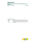
EEPROM Socket Board
User Manual v1.00
February 15, 2008
DIP/SOIC/TSSOP EEPROM Board User Manual
1 Overview
The EEPROM Socket Board provides embedded systems engineers with an easy and
cost-effective method of programming I2C- and SPI-based memory devices. Using Total
Phase's industry-leading host adapters and software, engineers can take full advantage
of the Flash Center™ programming software along with the Aardvark™ I2C/SPI Host
Adapter and the Cheetah™ SPI Host Adapter to program their Serial EEPROM memory
chips.
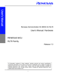
Figure 1 : Schematic of the EEPROM Socket Board
1.1 Features
• Flash and burn I2C and SPI EEPROMs that are in any of these standard chip
packages: DIP8, SOIC8 or TSSOP8.
• Specify 5 V, 3.3 V, or an external VDD Source at any voltage level.
• Connect or disconnect Slave Select (SS) and change the polarity of SS.
• Gang-Program multiple devices by using multiple socket board and programming
adapter sets in parallel on the same host computer.
2
DIP/SOIC/TSSOP EEPROM Board User Manual
1.2 What's Included
The EEPROM Socket Board comes complete with:
• EEPROM Socket Board
• 8-pin split ribbon cable
1.3 Flash Center Software
The Flash Center Software is a free software package that allows engineers to quickly
erase, program, and verify I2C- and SPI-based EEPROM and Flash memory chips that
are interfaced through an Aardvark I2C/SPI Host Adapter and/or Cheetah SPI Host
Adapter.
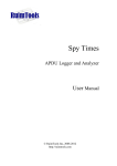
Figure 2 : The Flash Center Software is a free memory chip
programming software
1.3.1 Features
• Fast speeds – the Flash Center Software can read a typical 4 Megabyte flash
memory in 0.7 seconds.
• Gang programming support – the Flash Center Software can program multiple
devices in parallel by connecting to multiple Aardvark I2C/SPI Host Adapters and/or
Cheetah SPI Host Adapters on the same computer.
• Extensible device support – the Flash Center Software has an extensible XMLbased memory device library. By adding or modifying the XML descriptions of target
memory devices, developers can instantly support almost any I2C- or SPI-based
EEPROM or Serial Flash memory.
3
DIP/SOIC/TSSOP EEPROM Board User Manual
1.3.2 Minimum Requirements
• Linux (kernel 2.6 and above), Windows XP (SP2 or later), Windows Vista 32-bit/64-bit,
Windows 7 32-bit/64-bit
• One or more available High-speed USB 2.0 ports
• One or more Aardvark I2C/SPI Host Adapters and/or Cheetah SPI Host Adapters
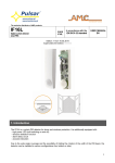
1.4 Aardvark I2C/SPI Host Adapter
The Aardvark I2C/SPI Host Adapteris a fast and powerful I2C bus and SPI bus host
adapter through USB. It allows a developer to interface a Linux or Windows PC to a
downstream embedded system environment and transfer serial messages using the I2C
and SPI protocols.
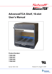
Figure 3 : The Aardvark I2C/SPI Host Adapter is a USB to I2C and SPI
adapter that allows developers to interface their computers to target
embedded systems.
1.4.1 Features
• I2C Master and Slave (1-800 kHz)
• SPI Master (up to 8 MHz) and Slave (up to 4 MHz)
• General Purpose I/O
• Windows and Linux support
4
DIP/SOIC/TSSOP EEPROM Board User Manual
• Free software and royalty-free API
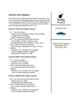
1.5 Cheetah SPI Host Adapter
The Cheetah SPI Host Adapter is a high-speed SPI adapter that is capable of
communicating over SPI at up to 40+ MHz. The Cheetah adapter is specifically designed
to communicate with high-speed, SPI-based Flash memory. It is an ideal tool to develop,
debug, and program SPI-based systems.
Figure 4 : The Cheetah SPI Host Adapter is a high-speed SPI Masteronly adapter. It is capable of signaling from 1 to 40+ MHz with no interbyte delays.
1.5.1 Features
• SPI Master signaling up to 40+ MHz
• Maximum throughput with no inter-byte delays
• User-configurable timing delays
• Windows and Linux support
• Free software and royalty-free API
5
DIP/SOIC/TSSOP EEPROM Board User Manual
2 Sockets
The EEPROM Socket Board offers three different sockets to interface with your memory
chip: DIP8, SOIC8 and TSSOP8. Please note that only one can be used at a time as
they are all cross-connected.
Figure 5 : The EEPROM Socket Board provides three different
sockets for interfacing with your stand-alone memory chip.
2.1 Compatible Chip Sizes
The three sockets of the EEPROM Socket Board are compatible with standard sized
chip packages. Figure 6 provides information about the supported sizes for all the
sockets. Please note that all measurements are in millimeters (mm).
6
DIP/SOIC/TSSOP EEPROM Board User Manual
Figure 6 : Diagrams of the supported package sizes. Please note that
the diagrams are not to scale.
Compatible chip sizes for each of the sockets available on the EEPROM Socket Board.
All measurements are in millimeters (mm).
DIP8 SOIC8 TSSOP8
Pitch
(P)
2.54
1.27
0.65
Thickness
(A)
3.94
1.90
1.00
Lead Tip-to-Tip Width
(E)
7.94
6.00
6.40
Molded Package Width (E1)
6.35
3.90
4.40
7
DIP/SOIC/TSSOP EEPROM Board User Manual
Overall Length
(D)
9.46
5.40
3.00
8
DIP/SOIC/TSSOP EEPROM Board User Manual
3 Connectors
3.1 Aardvark 1 and Aardvark 2
There are the two boxed connectors at the bottom of the EEPROM Socket Board which
are used to connect the board to an Aardvark I2C/SPI Host Adapter or a Cheetah SPI
Host Adapter. These two connectors are cross-connected, so it does not matter which
one is used. In most cases, you will only want to connect a single adapter to the
EEPROM Socket Board at a time.
The second connector is available to connect to a protocol analyzer or to cross connect
with another adapter for testing purposes. For example, an Aardvark adapter or a
Cheetah adapter can be connected to the board through Aardvark 1 to program the
memory chip. At the same time, a Beagle I2C/SPI Protocol Analyzer can be attached to
Aardvark 2 to monitor the bus while the chip is being programmed to ensure that the
data on the bus is correct.
3.2 External
Figure 7 : The External Connector (J1) provides the developer with a
quick and easy way to interface or monitor any or all of the EEPROM
Socket Board signals.
All the signals on the board are available for external monitoring through the External
connector (J1). The two VIN pins allow a user to use an external power source to power
9
DIP/SOIC/TSSOP EEPROM Board User Manual
the memory device. Please refer to the Programming a Device section for more
information.
3.3 Powering the EEPROM Socket Board
To power the EEPROM Socket Board, the Cheetah or Aardvark adapter must be
configured to send target power to the board. This can be accomplished via the Rosetta
Language Bindings, the Flash Center software, the Aardvark Control Center Software or
the Cheetah GUI Software. When powered-on, the board's Power LED will be lit.
3.4 Cross-Connecting Aardvark Adapters and/or Cheetah
Adapters
When cross-connecting two adapters, the board must be powered on. Otherwise, results
may be unpredictable. If you experience problems, please make sure that the
Power LED on the board is lit.
10
DIP/SOIC/TSSOP EEPROM Board User Manual
4 Programming a Device
I2C EEPROMs and SPI EEPROMs can be programmed using the Flash Center Software
in conjunction with an Aardvark adapter or a Cheetah adapter. Detailed technical
information about all these products can be found on Total Phase's website.
4.1 Inserting and Removing Device
To program a chip, insert the chip into the appropriate socket. Please note that all the
sockets are cross-connected, so it is only possible to use one socket at a time.
Whenever handling chips, always be sure to follow safe handling procedures to ensure
that the chips are not damaged.
4.1.1 DIP8
To insert a DIP8 chip, simply align the pins with the socket and firmly press the chip into
the socket.
To remove a DIP8 chip, we recommend that a DIP extractor tool is used to prevent
damage to the chip and its pins.
4.1.2 SOIC8 and TSSOP8
Both the SOIC8 and TSSOP8 sockets are zero insertion force sockets and work on the
same principle.
To insert a chip:
1. Press down on the top of the socket to raise the contact pins.
2. While pressing down on the socket, carefully place the chip into the
socket and make sure that the orientation of the chip is correct (pin 1
should always be in the top left corner).
3. Once the chip is in place, release the top of the socket to allow the contact
pins to drop and hold the chip in place.
At this point, the chip should be held securely in place. Please make sure that all the
contact pins have made contact with the correct pins on the chip.
When removing the chip, we recommend using a vacuum pickup tool to prevent damage
to the chip and its pins.
11
DIP/SOIC/TSSOP EEPROM Board User Manual
To remove a chip:
1. Press down on the top of the socket to raise the contact pins.
2. Carefully remove the chip using a vacuum pickup tool or equivalent tool.
3. Release the top of the socket.
4.2 Connecting the Pins
Since different chips have different pin configurations, the EEPROM Socket
Boardincludes a 8-pin split ribbon cable to allow you to connect the pins to the correct
sources.
Figure 8 : The Pin Board connector provides the developer with a
easy way to connect the correct signals to the appropriate pins of the
memory chip that is to be programmed. The included 8-pin split cable
can be used to connect the correct signal to the appropriate pin.
In the top left side of the board, you will notice that there is a graphic representation of a
chip with numbered pins from 1 to 8 (Figure 8). Along both sides of the drawing are two
(2) banks of 4-pin headers. These banks are connected to the eight (8) pins of the chip
in the socket. The pins of the chip should be connected to the appropriate sources as
described by the chip's datasheet.
Various sources are provided around the chip diagram. Along the top of the chip are five
(5) pins for VDD and along the bottom of the chip are five (5) pins for GND. To the left of
the chip are sources for the I2C and SPI pins. Each source is labeled along the left.
Figure 9 shows a EEPROM Socket Board that has been configured to program an I2C
EEPROM.
12
DIP/SOIC/TSSOP EEPROM Board User Manual
Figure 9 : This is the view from the top of the EEPROM Socket Board
which has been configured to program an I2C EEPROM which has
been loaded into the TSSOP8 socket. One end of the supplied 8-pin
ribbon cable has been connected to the eight (8) pins of Pin Board
connector around the graphic of the chip. The other end has been
connected to the appropriate sources as indicated by the device's
datasheet.
4.3 Powering the Device
Figure 10 : The EEPROM Socket Boardoffers two different voltage
levels: 5 V and 3.3 V. If another voltage level is desired, the develop
can select EXT and attach an external power source to the board.
There are multiple options for powering the device to be programmed. The Aardvark
adapter and Cheetah adapter are both able to send downstream power to the EEPROM
Socket Board which can be used to power the chip. Two different voltages are available:
5 V and 3.3 V. To select one of these voltages, simply use a jumper to short the pins
next to the appropriate voltage on the VDD Source connector (J2).
13
DIP/SOIC/TSSOP EEPROM Board User Manual
4.3.1 External Power Source
Figure 11 : When EXT is selected, an external power source can be
applied to the VIN pins in the External connector (J1).
If a different voltage is needed, it is possible to use an external power supply to provide
power to the target chip. To use an external power source, please use a jumper to short
the pins next to EXT (position 3) on the VDD Source connector (J2). Power should be
applied to the VIN pins on the External (J1) connector.
4.4 SPI Slave Select
Figure 12 : The developer can connect or disconnect Slave Select
(SS) pin as well as configure the polarity of SS on the board.
4.4.1 Connecting SS
Some SPI-based memory chips do not require the use of the Slave Select pin. In these
cases, the SS pin can be disconnected. To do this, simply remove the jumper from the
SS Connect header (J3).
14
DIP/SOIC/TSSOP EEPROM Board User Manual
4.4.2 SS Pull-down/Pull-up Resistors
The EEPROM Socket Board provides the ability either pull-down or pull-up the Slave
Select line depending on the requirements of the target device by using a jumper to short
pins on the (J4) connector.
To pull SS down, short pins 1 and 2.
To pull SS up, short pins 2 and 3.
15
DIP/SOIC/TSSOP EEPROM Board User Manual
5 Legal / Contact
5.1 Disclaimer
All of the software and documentation provided in this datasheet, is copyright Total
Phase, Inc. ("Total Phase"). License is granted to the user to freely use and distribute
the software and documentation in complete and unaltered form, provided that the
purpose is to use or evaluate Total Phase products. Distribution rights do not include
public posting or mirroring on Internet websites. Only a link to the Total Phase download
area can be provided on such public websites.
Total Phase shall in no event be liable to any party for direct, indirect, special, general,
incidental, or consequential damages arising from the use of its site, the software or
documentation downloaded from its site, or any derivative works thereof, even if Total
Phase or distributors have been advised of the possibility of such damage. The software,
its documentation, and any derivative works is provided on an "as-is" basis, and thus
comes with absolutely no warranty, either express or implied. This disclaimer includes,
but is not limited to, implied warranties of merchantability, fitness for any particular
purpose, and non-infringement. Total Phase and distributors have no obligation to
provide maintenance, support, or updates.
Information in this document is subject to change without notice and should not be
construed as a commitment by Total Phase. While the information contained herein is
believed to be accurate, Total Phase assumes no responsibility for any errors and/or
omissions that may appear in this document.
5.2 Life Support Equipment Policy
Total Phase products are not authorized for use in life support devices or systems. Life
support devices or systems include, but are not limited to, surgical implants, medical
systems, and other safety-critical systems in which failure of a Total Phase product could
cause personal injury or loss of life. Should a Total Phase product be used in such an
unauthorized manner, Buyer agrees to indemnify and hold harmless Total Phase, its
officers, employees, affiliates, and distributors from any and all claims arising from such
use, even if such claim alleges that Total Phase was negligent in the design or
manufacture of its product.
5.3 Contact Information
Total Phase can be found on the Internet at http://www.totalphase.com/. If you have
support-related questions, please email the product engineers at
[email protected]. For sales inquiries, please contact [email protected].
16
DIP/SOIC/TSSOP EEPROM Board User Manual
©2010-2008 Total Phase, Inc.
All rights reserved.
17