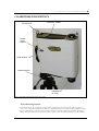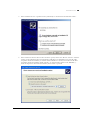
1
SVC HR-1024i / SVC HR-768i USER MANUAL Revision 1.5 29 Firemens Way, Poughkeepsie, New York 12603 Voice: (845) 471-7007, Fax: (845) 471-7020, E-mail: [email protected] Copyright 2012 Spectra Vista Corporation SECTION 1 - SPECTRORADIOMETER .........................................................................................................1 1. INTRODUCTION ...........................................................................................................................................1 2. HARDWARE DESCRIPTION .......................................................................................................................2 Tripod Mounting Options .................................................................................................................................2 Foreoptic Options ............................................................................................................................................3 Battery Pack .....................................................................................................................................................4 Support Feet .....................................................................................................................................................5 Hand Strap .......................................................................................................................................................5 Laser Scan Switch ............................................................................................................................................6 Laser Pointer....................................................................................................................................................6 JPEG Camera ..................................................................................................................................................6 3. CONTROL PANEL.........................................................................................................................................6 Data Connections .............................................................................................................................................6 Indicators .........................................................................................................................................................7 Power Switch....................................................................................................................................................7 GPS Antenna ....................................................................................................................................................7 LCD Display ....................................................................................................................................................7 SECTION 2 – PC DATA ACQUISITION SOFTWARE ..................................................................................8 1. INSTALLATION/REMOVAL .......................................................................................................................8 Recommended System Requirements ...............................................................................................................8 Installation Steps ..............................................................................................................................................8 Removing The Software....................................................................................................................................9 2. INTRODUCTION .........................................................................................................................................10 3. DESCRIPTION .............................................................................................................................................14 Menu Selection Summary ...............................................................................................................................14 File .................................................................................................................................................................14 NEW............................................................................................................................................................................. 14 OPEN ........................................................................................................................................................................... 16 SAVE AS … ................................................................................................................................................................ 17 CLOSE ......................................................................................................................................................................... 18 CLOSE ALL................................................................................................................................................................. 18 PRINT .......................................................................................................................................................................... 18 DATA OPTIONS ......................................................................................................................................................... 19 EXIT............................................................................................................................................................................. 20 Control ...........................................................................................................................................................20 SETUP INSTRUMENT… ........................................................................................................................................... 20 SETUP OVERLAP/MATCHING… ............................................................................................................................ 23 SETUP EXTERNAL DATA … ................................................................................................................................... 25 READ MEMORY … ................................................................................................................................................... 28 TIMED SCANS … ...................................................................................................................................................... 30 SETUP GPS … ............................................................................................................................................................ 32 Tools ...............................................................................................................................................................35 SIG FILE MERGE… ................................................................................................................................................... 35 SIG FILE OVERLAP/MATCHING…......................................................................................................................... 36 WHITE PLATE REFLECTANCE… ........................................................................................................................... 37 RESAMPLE SPECTRAL DATA… ............................................................................................................................ 39 INSTRUMENT CALIBRATION DATA… ................................................................................................................. 40 REMOTE ACCESS SERVER… ................................................................................................................................. 44 Window...........................................................................................................................................................46 SINGLE GRAPH ......................................................................................................................................................... 46 MULTI GRAPH ........................................................................................................................................................... 47 PLOT SETTINGS … ................................................................................................................................................... 48 LARGER BUTTONS ................................................................................................................................................... 50 About ..............................................................................................................................................................50 SECTION 3 – OPERATION .............................................................................................................................51 1. SETUP ............................................................................................................................................................51 Battery Pack ...................................................................................................................................................51 Instrument Power-on Time .............................................................................................................................51 SVC HR-1024i/HR-768i USER MANUAL REV 1.5 Instrument Warm-up Time .............................................................................................................................51 Instrument Orientation ...................................................................................................................................51 Laser (Tripod or Hand-held)..........................................................................................................................51 Field of View ..................................................................................................................................................52 2. CONNECTING THE INSTRUMENT TO A COMPUTER .........................................................................................53 3. STAND-ALONE DATA ACQUISITION ...............................................................................................................53 Operation Via The LCD Display ....................................................................................................................53 Reflectance Measurement Overview ..............................................................................................................56 Taking a REFERENCE Measurement............................................................................................................56 Taking a TARGET Measurement ...................................................................................................................57 Downloading Stand-alone Measurements .....................................................................................................57 4. PC DATA ACQUISITION ..................................................................................................................................58 5. PDA DATA ACQUISITION ...............................................................................................................................58 SECTION 4 – BATTERY CHARGER .............................................................................................................59 1. INTRODUCTION ...............................................................................................................................................59 2. CHARGER SPECIFICATIONS .............................................................................................................................59 3. BATTERY PACK INFORMATION AND WARNINGS ............................................................................................59 4. CHARGING ......................................................................................................................................................60 APPENDIX A1 – HR-1024I SPECIFICATIONS ............................................................................................61 APPENDIX A2 – HR-768I SPECIFICATIONS ..............................................................................................62 APPENDIX B – FILE DESCRIPTIONS ..........................................................................................................63 SIGNATURE FILE FORMAT ..................................................................................................................................63 WHITE PLATE REFLECTANCE DATA FILE FORMAT .............................................................................................67 PDA SOFTWARE COM PORT CONFIGURATION FILE...........................................................................................68 APPENDIX C – LASER SAFETY ....................................................................................................................69 APPENDIX D – PC THIRD PARTY BLUETOOTH USAGE .......................................................................70 INSTRUMENT-SPECIFIC BLUETOOTH INFORMATION ...........................................................................................70 APPENDIX E – PC USB DEVICE DRIVERS .................................................................................................71 INSTALLING USB DEVICE DRIVERS ON THE PC ................................................................................................71 REMOVING USB DEVICE DRIVERS FROM THE PC .............................................................................................75 APPENDIX F – PDA DATA ACQUISITION SOFTWARE ..........................................................................76 OVERVIEW .........................................................................................................................................................76 PDA REQUIREMENTS .........................................................................................................................................76 PDA SOFTWARE – QUICK REFERENCE ...............................................................................................................77 PDA SOFTWARE APPLICATION – DETAILED USAGE ...........................................................................................78 Introduction....................................................................................................................................................78 Data File Format ...........................................................................................................................................78 Data File Naming Convention (AutoSave) ................................................................................................................... 78 Data File Location ........................................................................................................................................................ 78 Startup ............................................................................................................................................................78 Operation .......................................................................................................................................................79 COMMAND Button “REFERENCE” ........................................................................................................................... 79 COMMAND Button “TARGET” .................................................................................................................................. 79 Menu Button “FILE” .................................................................................................................................................. 80 Menu Button “Graph” ................................................................................................................................................ 81 Menu Button “Instrument” .................................................................................................................................... 81 Settings Form ............................................................................................................................................................... 83 Menu Button “HELP” .................................................................................................................................................. 84 APPENDIX J – PDA USAGE TIPS ..................................................................................................................85 PDA SOFT RESET PROCEDURE – RECON 400X ..................................................................................................85 SVC HR-1024i/HR-768i USER MANUAL REV 1.5 PDA HARD RESET PROCEDURE – RECON 400X.................................................................................................85 PDA POWER UP .................................................................................................................................................86 PDA CHARGING .................................................................................................................................................86 PDA COM PORTS AND PDA APPLICATION SOFTWARE .....................................................................................86 APPENDIX K – INSTRUMENT REMOTE ACCESS ...................................................................................88 GENERAL PROTOCOL DESCRIPTION ........................................................................................................88 DETAILED PROTOCOL DESCRIPTION .......................................................................................................88 Reference Scan Command..............................................................................................................................88 Target Scan Command ...................................................................................................................................88 Unknown Commands .....................................................................................................................................89 Busy Errors ....................................................................................................................................................89 APPENDIX N – FIBER OPTIC INSTALLATION .........................................................................................90 APPENDIX O – OPTIONAL FAN INSTALLATION ....................................................................................91 APPENDIX Z – INSTRUMENT FOV DIAGRAM(S) ....................................................................................92 SVC HR-1024i/HR-768i USER MANUAL REV 1.5 S V C H R 1 0 2 4 i S P E C T R O R A D I O M E T E R Section 1 - Spectroradiometer 1. INTRODUCTION This User Manual applies to the following SVC field-portable spectroradiometer products: • The HR-1024i covers the UV, Visible, and NIR wavelengths from 350 nm to 2500 nm. It uses 3 diffraction grating spectrometers with 1silicon and 2 InGaAs diode arrays. The silicon array has 512 discrete detectors and the InGaAs arrays each have 256 discrete detectors that provide the capability to read 1024 spectral bands. • The HR-768i covers the UV, Visible, and NIR wavelengths from 350 nm to 2500 nm. It uses 3 diffraction grating spectrometers with 1silicon and 2 InGaAs diode arrays. The silicon array has 512 discrete detectors and the InGaAs arrays each have 128 discrete detectors that provide the capability to read 768 spectral bands. The spectroradiometer includes memory and a display for stand-alone operation as well as capability for personal computer (PC) and personal data assistant (PDA) assisted operation. PC communications to the instrument are available through its USB client port, a Bluetooth wireless connection, or via RS-232. A PDA may control the instrument via a Bluetooth connection or via RS-232. The instrument includes a second Bluetooth channel that may optionally communicate with an external sensor suite (future development). When operated in stand-alone mode, up to 1000 spectral readings can be stored in the instrument for subsequent down loading and analysis using a PC. All spectroradiometer identification and calibration information is stored on board, so there are no external files to manage. The instrument contains an internal GPS device to record the latitude, longitude, and time of each spectral reading. This instrument is self contained and incorporates an easily replaceable battery called a SMARTPACK. The battery chargers supplied with the instrument have the capability to charge the LI-Ion batteries from line voltage with the AC adapter. The computer based operation allows for real time data display and data analysis. Radiance and percent reflectance are provided within the acquisition software. Stand-alone operation makes this same information available for display on the instrument’s LCD (liquid crystal display), which is located on the rear panel on the instrument. A full range of options are available. These options include alternate foreoptics, fiber optic light guides, irradiance spheres, cosine diffusers, Reflectance Probe, back packs, white reference panels, tripods and other custom engineered field devices. SVC HR-1024i/HR-768i USER MANUAL REV 1.5 1 S V C H R 1 0 2 4 i S P E C T R O R A D I O M E T E R 2. HARDWARE DESCRIPTION CONTROL PANEL LIFTING EYE LASER SCAN SWITCH HAND STRAP TRIPOD MOUNT FOREOPTIC (4° FOV) Figure 1 Instrument attached to tripod via front panel Tripod Mounting Options The instrument can be mounted to a tripod on the front panel (as shown in Figure 1 above) using 1 or more of 5 1/4-20 UNC threaded holes that are compatible with most conventional photographic or video tripods. Alternatively, a tripod can be mounted at the bottom of the optical plate (as shown in Figure 2 below) where the hole location is near the center of gravity of the instrument with battery pack installed. SVC HR-1024i/HR-768i USER MANUAL REV 1.5 2 S V C BATTERY PACK (PARTIALLY RETRACTED) H R 1 0 2 4 i S P E C T R O R A D I O M E T E R USB–B CONNECTOR BATTERY CONTACT BATTERY LATCH SUPPORT FOOT (RETRACTED) TRIPOD MOUNT HOLE Figure 2 Instrument bottom view Foreoptic Options Different foreoptics can be attached to provide different fields of view (FOV) to enable the instrument to look at different size targets. Normally the target is at a distance of 1m from the optical element. See section 3 item 1 for the field of view setup. Measurements can be taken at further distances but the target size will be larger. The foreoptics are mounted in lens barrels or adapters that are secured to the unit by hand using a threaded collar and are keyed to go in at the same clock angle to maintain consistent radiometric readings. The following foreoptics are available: (1) 4° nominal FOV lens (standard) (2) 8° nominal FOV lens (optional) (3) 14° nominal FOV lens (optional) SVC HR-1024i/HR-768i USER MANUAL REV 1.5 3 S V C H R 1 0 2 4 i S P E C T R O R A D I O M E T E R (4) 25° FOV fiber optic light guide, various lengths (optional) (5) 180° Irradiance Sphere(optional) NOTES: When optics are installed or changed, the proper radiometric calibration must be applied to the software. The entry of this information is provided for in the Control Setup software section of the manual. Always screw the threaded collar until hand tight point. Do not over-tighten. Battery Pack The instrument’s Battery Pack provides power for portable operation. The battery pack installs via dovetail slides and automatically latches into position to engage the battery contacts on the bottom of the instrument. The Li-ION battery is 7.4V nominal and connects directly to the instrument. This battery is designed to provide over 3 hours operation following a full charge. When the battery is inserted, power can be applied to the instrument. When the battery voltage is too low to power the instrument, it will turn off and go to 0 volts. The battery can then be charged via the charging connector with the supplied charger. Refer to Section 4 – Battery Charger for charging details. PULL HANDLE COVER PLATE CHARGE JACK ELECTRICAL CONTACTS Figure 3 Battery Pack SVC HR-1024i/HR-768i USER MANUAL REV 1.5 4 S V C H R 1 0 2 4 i S P E C T R O R A D I O M E T E R FRONT PANEL TRIPOD MOUNTING HOLES JPG CAMERA WINDOW LASER POINTER WINDOW FOREOPTIC RETAINING RING FOREOPTIC (8° FOV) Figure 4 Front Panel Support Feet The support feet can be moved between the retracted and extended positions. When extended they allow the instrument to rest level on a flat surface when the battery pack is installed. Hand Strap The hand strap is adjustable and allows holding of the instrument with the right hand whilst actuating the laser scan switch with the right index finger. SVC HR-1024i/HR-768i USER MANUAL REV 1.5 5 S V C H R 1 0 2 4 i S P E C T R O R A D I O M E T E R Laser Scan Switch The Laser Scan Switch is a pushbutton type that can both actuate the sighting laser and initiate the start of the spectral scan. (More detail is provided in Section 3). Laser Pointer The laser beam projects thru the laser pointer window close to the objective lenses and is aligned parallel to the axis of these lenses. JPEG Camera The internal JPEG camera views thru a protective window as shown above. It is a miniature camera with a 60° field of view and is focused for maximum depth of field from 1m to infinity. It outputs a either a 640x480 or 320x240 pixel image of the spectral target sample and surrounding area. 3. CONTROL PANEL The control panel of the instrument contains the controls and displays that are required for stand alone operation. BLUETOOTH ANTENNA EXTERNAL TRIGGER CONNECTOR LCD DISPLAY AUX. BLUETOOTH ANTENNA CONNECTION LEDs POWER SWITCH GPS ANTENNA USB A PORT Figure 5 Control Panel Data Connections The instrument has 3 connectors that may be used to communicate with external devices; two of these connections are located on the Control Panel, one is located on the bottom of the unit: SVC HR-1024i/HR-768i USER MANUAL REV 1.5 6 S V C H R 1 0 2 4 i S P E C T R O R A D I O M E T E R AUX The AUX port is a round 12-pin connector located on the left side of the control panel. It serves as an RS-232 serial port, an external trigger connector, and as a source of power for optional equipment. USB A The USB A Port is for future use. The USB client port on the bottom of the instrument is for computer assisted operation. Bluetooth The Bluetooth antenna is for computer assisted operation. Indicators The Control Panel has 3 LED status indicators. Laser LED The laser indicator is illuminated when the laser is on. Ready LED Is illuminated when the instrument is ready to take a scan. Power LED The power indicator is illuminated when the power is on. Power Switch The power switch provides on/off control of the unit. GPS Antenna The GPS Antenna dome is positioned on the control panel for optimal orientation for receiving signals from a GPS satellite when the instrument is in the typical orientation of pointing downwards to look at a spectral target. LCD Display The LCD display is useful for acquiring spectral data in stand-alone operation (see section 3 item 3). It is a standard 4.3” diagonal module with LED backlighting and a 480 x 272 pixel resolution, incorporating a resistive touch screen designed to use finger inputs (no stylus needed.) Text and icons are high contrast, designed to be read in direct sunlight conditions. Spectral plots are viewable from the display. SVC HR-1024i/HR-768i USER MANUAL REV 1.5 7 S V C H R 1 0 2 4 i S P E C T R O R A D I O M E T E R Section 2 – PC Data Acquisition Software 1. INSTALLATION/REMOVAL The instrument’s PC Data Acquisition Software is supplied either on CD or in single-executable format, and provides for step-by-step installation onto a Windows PC or notebook computer. The installation media is used to install the PC Data Acquisition software into an installation directory (typically, C:\Program Files\Spectra Vista\HR1024i\ or C:\Program Files\Spectra Vista\HR768i\) on the computer’s hard disk drive. Recommended System Requirements • Operating System: Windows XP/ 7 • CPU: 500Mhz Intel (or compatible) • Memory: 512M (or greater) of main memory • Screen Resolution: 1024x768 (or greater) • Serial /USB port: Provided by a built-in COM (9-pin D) port, a USB-to-Serial Adapter, or via a Bluetooth interface (Bluetooth Serial Port) Installation Steps Prior to installation, reboot the computer to ensure that Windows is in a stable state, and has as few applications running as possible. To install the software from the CD, simply insert the installation CD into the CD drive within the computer where you want to install the software. A screen similar to the one shown below will appear in less than 1 minute. Follow the on-screen prompts to install the PC Data Acquisition software. SVC HR-1024i/HR-768i USER MANUAL REV 1.5 8 S V C H R 1 0 2 4 i S P E C T R O R A D I O M E T E R If the screen shown above does not appear within 60 seconds: • Use Windows Explorer to explore the CD. • Double-click on the “setup.exe” file located on the CD in order to manually run the setup. Removing The Software The Data Acquisition Software may be removed by using the standard Windows program removal tool found under Start -> Settings -> Control Panel -> Add or Remove Programs. Scroll down through the list of installed programs and select the entry “SVC HR-1024i Data Acquisition Software” or “SVC HR-768i Data Acquisition Software”. Press the “Remove” button to remove the software: Note that only the software will be removed; any data files acquired will remain on the computer’s disk. SVC HR-1024i/HR-768i USER MANUAL REV 1.5 9 S V C H R 1 0 2 4 i S P E C T R O R A D I O M E T E R 1 0 2. INTRODUCTION The PC Data Acquisition Software provides the user with a flexible, easy to use software package. The PC Data Acquisition Software is used to acquire data from the instrument, store data to files on disk, and display data graphically. The PC Data Acquisition Software can modify spectroradiometer parameters, take spectral measurements, and download spectral measurements from the on-board memory of the HR-1024i or HR-768i to files on disk. The PC Data Acquisition Software allows data to be configured and stored to a file on disk when taking a spectral measurement. The software has a number of features that provide a great deal of flexibility for spectral data acquisition, display, and storage: • • • • • • Data files can be configured as SIG Files for use with PC Data Acquisition Software; SIG Files are saved to disk and may read back into the PC Data Acquisition Software at a later time for analysis. Data files can be configured as user defined ASCII Files for export to other software packages; ASCII format files cannot be read back into the PC Data Acquisition Software at a later time. Data files can be automatically created and given an incremental extension at the end of the acquisition. Data can be saved to a unique file name at the end of the acquisition. New data may be acquired manually by clicking the mouse on a button or pressing a “hot key”; or new data may be taken automatically using a configurable timer. Spectral data may be displayed in one of two ways: o “Single Graph” mode, which displays the Reference and Target Radiance on the left Y-axis and the Percent Reflectance on the right Y-axis for a single measurement. o “Multi Graph” mode, which displays the Reference Radiance, Target Radiance, or Percent Reflectance of up to 24 measurements in one graph. Several tools are built into the software that allow SIG format data files to be merged, re-sampled, or reprocessed automatically (see the Tools Menu description below.) The Data Acquisition Software’s initial screen is shown below. SVC HR-1024i/HR-768i USER MANUAL REV 1.5 S V C H R 1 0 2 4 i S P E C T R O R A D I O M E T E R 1 1 The screen above is divided into several areas, as described below: The application’s Title Bar displays the Current Working Folder – that is, the folder where new scans (real-time or downloaded) are saved, and where old scans may be opened and displayed. The location of the current working folder is retained in the Windows Registry. The location of the current working folder may be changed with the File->New… or File->Open… dialogs. The Main Menu allows the operator to open/save files and configure both the instrument settings and the display of spectral data. Each menu item is discussed in detail in subsequent sections. The Reference Scan Button causes the instrument to take and graphically display reference data. This button may also be activated by pressing either the “R” or “F1” key on the keyboard. SVC HR-1024i/HR-768i USER MANUAL REV 1.5 S V C H R 1 0 2 4 i S P E C T R O R A D I O M E T E R 1 2 The Target Scan Button, when left-clicked, causes the instrument to take and graphically display a single target data set. This button may also be activated by pressing either the “T” or”F2” key on the keyboard. The Acquire Multiple Target Scans dialog allows the operator to take multiple scans of the same target sequentially. This pop-up dialog appears when the Target Scan Button is right-clicked, and may also be activated by pressing the “M” or “F4” key on the keyboard. The External Data Scan Button only appears in the GUI when the optional External Data Interface has been installed in the instrument, and has been configured for display. This button may also be activated by pressing the “E” key on the keyboard. See the section SETUP EXTERNAL DATA … below for more details. The File Stack Area shows the list of data files that are currently open. It also allows the operator to select which files to graph in single-graph mode by doubleclicking. The Plot Types Control allows the operator to select the type of data displayed in the graph area. The Status Bar Area displays the channel number, the wavelength, and the Radiance/ Reflectance value of a selected data point on a displayed graph. A data point in a graph is selected by moving the cursor to the point of interest, and clicking the left mouse button on the point. The Last Scan Information Box shows information about the last reference or target scan acquired by the Data Acquisition Software. SVC HR-1024i/HR-768i USER MANUAL REV 1.5 S V C H R 1 0 2 4 i S P E C T R O R A D I O M E T E R 1 3 The External Data Display Frame only appears in the GUI when the optional External Data Interface has been installed in the instrument, and configured for display. See the section SETUP EXTERNAL DATA … below for more details. The large white area displays single-graph or multi-graph data sets. The Graphing Area operates in two modes, Zoom Mode and Normal Mode. (Graphing Area) ZOOM MODE: A rectangular area of interest may be magnified by holding down the left mouse button while “dragging” a rectangular area across the graph. When the left mouse button is released, the graph is re-drawn to contain only the dragged rectangle. NORMAL MODE: Click the right mouse button anywhere in the graph area to restore the magnification to normal. SVC HR-1024i/HR-768i USER MANUAL REV 1.5 S V C H R 1 0 2 4 i S P E C T R O R A D I O M E T E R 1 4 3. DESCRIPTION Menu Selection Summary File Provides a menu of options pertaining to Data Files. Control Provides a menu of options to control Spectroradiometer operations. Tools Provides a menu of available tools for enhancing spectral data. Window Provides a menu of available Window displays and settings. About Provides a dialog box of software and spectroradiometer data. File The File menu item provides the following drop-down menu of file controls. NEW Modifies the filename configuration used for storing spectral response measurement when the ‘Autosave’ feature is being used. The following standard Windows file dialog box appears when “New” is selected. Note that the dialog style may vary slightly with different versions of the Windows OS. SVC HR-1024i/HR-768i USER MANUAL REV 1.5 S V C File name H R 1 0 2 4 i S P E C T R O R A D I O M E T E R 1 5 Modifies the Base of the filename used with the Autosave feature. The filename of a spectral measurement acquired in Autosave mode is the File Base with an incremental extension automatically provided by the software. Ex. If the file base is “Test”, the first filename is “Test_000.sig”, the second is “Test._001.sig”, etc… When entering the new base name into the File name box, do not include any filename extensions, as the software will automatically add the appropriate extension as each data set is acquired. Files list Displays the files that exist in the current drive, directory, and search pattern. File of type This box has no purpose other than to display instructions to the user. Open Accepts the new base file name entered. Cancel Cancels the operation. SVC HR-1024i/HR-768i USER MANUAL REV 1.5 S V C H R 1 0 2 4 i S P E C T R O R A D I O M E T E R 1 6 OPEN Opens the files to be displayed in multi-graph mode. The following standard Windows file open dialog box appears when “Open” is selected. Note that the dialog style may vary slightly with different versions of the Windows OS. File name Selects the file(s) to be opened. A single left-mouse click selects a single fields or <Ctrl> + left-click or <Shift> + leftclick can be used to select multiple files. NOTE: The multi-graph is limited to twenty-four (24) plots. File Type Modifies the current search pattern used for displaying the existing files in the Files Box. Only “SIG” format files may be opened by the Data Acquisition software. Open Opens the selected file(s) for display in the multi-graph. SVC HR-1024i/HR-768i USER MANUAL REV 1.5 S V C Cancel H R 1 0 2 4 i S P E C T R O R A D I O M E T E R 1 7 Exits the dialog box without opening a file. SAVE AS … Saves the data that is currently contained in the single graph. In order to use the Save As… function, the graphing software must be in Single Graph mode, displaying the data file that is to be saved. The following standard Windows file save dialog box appears when “Save As” is selected. Note that the dialog style may vary slightly with different versions of the Windows OS. File name Allows the desired filename for data storage to be entered. If no extension or an invalid extension is entered, then one is supplied, based on the current file format. Files list Displays the files that exist in the current drive, directory, and search pattern. SVC HR-1024i/HR-768i USER MANUAL REV 1.5 S V C H R 1 0 2 4 i S P E C T R O R A D I O M E T E R Save As Type Modifies the current search pattern used for displaying the existing files in the Files Box. Only the currently selected format may be saved. The file format is selected by using the File->Data Options->Format menu to choose between “SIG” and “ascii” output file format. Save Saves the data contained in the single graph to the specified filename and exits the dialog box. Cancel Exits the dialog box without saving the file. 1 8 CLOSE Closes the data files that are selected in the File Stack of the multi-graph. The multi-graph is redrawn after the files are closed. CLOSE ALL Closes all files in the File Stack. PRINT Opens a standard Windows print dialog box. The current graph view may be printed using this dialog. SVC HR-1024i/HR-768i USER MANUAL REV 1.5 S V C H R 1 0 2 4 i S P E C T R O R A D I O M E T E R 1 9 DATA OPTIONS Configures how and when spectral measurements are stored to a files on a disk. Autosave When this item is checked, the Autosave feature is turned on. When Autosave is on, spectral measurements are automatically saved to files on disk using the current File Basename and an incremental extension. The default filename configuration uses the installation data directory (typically C:\Program Files\Spectra Vista\HR1024i\Data\) and the current File Basename determined by “gr” and the month, day, and year (Ex. “gr052105”). When the Autosave is turned on, the Prompt For Save option is disabled. Prompt For Save When this item is checked, the operator is prompted for a filename to store the data after the completion of each spectral measurement. Format… Configures the data output file. Choosing “Format…” displays the following dialog box: Output File Format Provides for the selection of one of the following: • SIG File This is the format compatible with the PC Data Acquisition software; spectral data saved in this SVC HR-1024i/HR-768i USER MANUAL REV 1.5 S V C H R 1 0 2 4 i S P E C T R O R A D I O M E T E R 2 0 format may be read back and displayed at some future time by the PC Data Acquisition Software • Ascii File Check the column(s) of data that will appear in the ASCII data file. The options are: Header information, including instrument settings, date/time, etc. Wavelength in nanometers Reference Radiance in W/cm2/nm/sr*1010 Target Radiance in W/cm2/nm/ sr*10-10 Percent Reflectance OK Implements the selected file format and exits the dialog box. Cancel Ignores the modifications made to the file format and exits the dialog box. EXIT Exits the PC Data Acquisition Software program. Control The control menu item provides the following drop-down menu of instrument controls: SETUP INSTRUMENT… Configures the Computer Port used for communications with the instrument. Once connected, sets the spectroradiometer operating parameters. SVC HR-1024i/HR-768i USER MANUAL REV 1.5 S V C H R 1 0 2 4 i S P E C T R O R A D I O M E T E R 2 1 When “Setup Instrument…” is selected, the software presents the following setup dialog box: Computer Port Control Frame: List Only Configured Ports When selected, only ports that are physically configured into the host computer are listed in the Port control. The list of configured ports is built only once each time the Data Acquisition Program is run. List All Possible Ports When selected, all 255 ports are listed in the Port control. Use this option if a virtual port (usually a Bluetooth port) that you want to use is not present in the “configured” list above. SVC HR-1024i/HR-768i USER MANUAL REV 1.5 S V C Port H R 1 0 2 4 i S P E C T R O R A D I O M E T E R 2 2 Selects/displays the serial communications COM port used to communicate with the instrument. The actual physical hardware associated with the COM port may be provided by a standard DB-9 hardware interface installed in the PC; It may also be realized by several other means that provide a “virtual” COM port (Bluetooth Serial Port, USB-to-Serial Adapter, or USB COM driver). See the Operations section, sub-section 2. Connecting The Instrument To A Computer, for more details. Connect Establishes a connection to the instrument, and downloads the information necessary to acquire and process spectral data. Disconnect Closes the connection. . Settings Frame Modifies the instrument settings. This frame is only enabled after the PC Acquisition Software has established a connection with an instrument. Optic Selects the entrance optic that is currently installed on the instrument. NOTE: The Special “Unity” entrance optic provides raw measurements without any radiometric calibration applied. Scan Time Modifies the instrument’s scan time parameter, which controls how long (in seconds) a spectral scan will take. Higher settings can reduce noise, but scans will take longer to complete. Integration Time The time in milliseconds allowed for the individual detectors to accumulate a reading. Higher settings can reduce noise, but the scans will take longer to complete. The “Auto” check box allows the instrument to select the optimum integration time. Date/Time Displays the current date/time stored in the instrument’s real time clock. If the displayed date/time is changed, the new settings are downloaded to the SVC HR-1024i/HR-768i USER MANUAL REV 1.5 S V C H R 1 0 2 4 i S P E C T R O R A D I O M E T E R 2 3 instrument if the “OK” button is selected. Stored Scans Displays the number of scans currently stored in the instrument’s internal memory. Auto Dark When checked, dark data is taken just prior to each reference and target scan; the dark current is measured and recorded using only the current integration settings. When unchecked, dark data is not taken just prior to each reference and target scans; instead, the dark measurement from the last actual dark acquisition (taken via the button labeled “Dark” on the main screen) is used. Integration Scales RAW DN Data When checked, and when the instrument’s “RAW DN” optic is selected, the RAW DN data will be scaled appropriately by the reported integration times. Use this checkbox when acquiring reflectance data in RAW DN mode. When unchecked, RAW DN data is not scaled by the integration times. OK If connected to an instrument, the settings shown are downloaded to the instrument, and the dialog exits. Cancel Exits the dialog without saving or sending any instrument settings. SETUP OVERLAP/MATCHING… Configures how to handle overlapped detector data. When “Setup Overlap/Matching…” is selected, the software presents the following dialog box. SVC HR-1024i/HR-768i USER MANUAL REV 1.5 S V C H R 1 0 2 4 i S P E C T R O R A D I O M E T E R 2 4 Overlap Frame: Preserve Overlapped Detector Data When this option is selected, the Transition Wvl setting is ignored and has no effect. All spectral data is preserved in the output file as each scan is acquired. Remove Overlapped Detector Data When this option is selected, the Transition Wvl fields control where the Si->Swir1 and Swir1->Swir2 transitions takes place. All overlapping spectral data is removed. Si->Swir1 Transition Wvl When in “Remove Overlap” mode, Sets the point where the Si detector data ends, and the first InGaAs detector data begins, when the “Remove Overlapped Detector Data” option is selected. Swir1->Swir2 Transition Wvl When in “Remove Overlap” mode, Sets the point where the first InGaAs detector data ends, and the second InGaAs detector data begins, when the “Remove Overlapped Detector Data” option is selected. Matching Type Frame Controls the method of matching Si and InGaAs detector data. SVC HR-1024i/HR-768i USER MANUAL REV 1.5 S V C H R 1 0 2 4 i S P E C T R O R A D I O M E T E R None No matching take place. When this option is in effect, none of the other Matching parameters has any effect on spectral data. Radiance Uses the detectors’ radiance curve data to perform matching on both the Reference and Target scans separately. Reflectance Combine the Reference and Target scans into a reflectance curve, and uses this curve’s data to perform matching. Matching Region Frame Defines the region over which the Si and first InGaAs data is examined in order to perform detector matching. Beginning Wvl The beginning wavelength in the matching region. This settings has no effect if “Matching Type” is set to “None” Ending Wvl The ending wavelength in the matching region. This setting has no effect if “Matching Type” is set to “None”. Matching Factor Limits Frame Defines the range of acceptable values for the factor used to match Silicon data to SWIR data. Min The minimum matching factor value. Max The maximum matching factor value. 2 5 Use NIR-SWIR Overlap Algorithm Frame Use The NIR-SWIR Overlap Algorithm… When checked, the Silicon and SWIR1 data are combined (within the Overlap Region) using a combination of the two overlapping detector data sets. Using this option only affects the data within the Overlap Region. This algorithm is applied after the standard matching algorithm is applied (See Matching Type Frame instructions above). SETUP EXTERNAL DATA … Configures the instrument’s optional external data interface. SVC HR-1024i/HR-768i USER MANUAL REV 1.5 S V C H R 1 0 2 4 i S P E C T R O R A D I O M E T E R 2 6 The instrument or PC may optionally be configured with an external sensor data interface. This interface allows the PC software to digitize, display, and store the data from up to 8 external sensor that are attached to the external interface. The Setup External Data dialog determines which, if any, of the external sensors’ data is saved to SIG files and/or displayed in the main GUI display When selected, the Setup External Data command displays the following dialog: External Data Source: Selects the source for the external data: None – disables external data acquisition. SVC HR-1024i/HR-768i USER MANUAL REV 1.5 S V C H R 1 0 2 4 i S P E C T R O R A D I O M E T E R 2 7 HR-1024i/HR-768i – use the optional external data interface within the HR1024i/HR-768i instrument for external data acquisition. Note that the “Gains” column of controls is disabled in this mode, since this interface has fixed hardware gains. SVC EDI-8 – use the EDI-8 module for external data acquisition. The “Gains” column is enabled, as this interface supports several different amplifier gains. Ch 1-8 Enabled: When checked, the data from that external channel will be saved in the header of the SIG file. When unchecked, that channel will be ignored, and a zero value will be stored in its place in the SIG header. Gain: Sets the desired gain for each external data channel; valid for SVC EDI-8 mode only. Display Ch. A-B: These two drop-down menus determine which (if any) of the 8 external channels are displayed in the main GUI screen. When either 1 or 2 channels are selected for display, the main GUI screen shows two additional elements for control and display of the external data, as described below: Press the External Data Scan button when a new set of external data samples is desired. No spectral data is acquired when this button is pressed, and only the Last Scan values (see below) are updated. The External Data Display frame displays the data from the selected External Data channels: Channel: The Channel number for that column. Dark: The most recent Dark Scan values taken. When updated, the Reference and Last Scan fields are reset. Reference: The most recent Reference Scan values. When updated, the Last Scan fields are reset. Last Scan: The most recent values/percentages taken during either a Target Scan, or an External Data Scan. The percentage is computed by dividing Last Scan by Reference. Adjust Display Values For External Dark Current: When checked, dark current correction is applied to the data displayed in the main GUI. When unchecked, dark current correction is not applied. This control has no effect on the data saved to the SIG file header. SVC HR-1024i/HR-768i USER MANUAL REV 1.5 S V C H R 1 0 2 4 i S P E C T R O R A D I O M E T E R Cancel: Dismiss the dialog without saving changes. OK: Apply the settings shown in the dialog. 2 8 READ MEMORY … Reads (downloads) the instrument’s stand-alone scans from the internal memory into the PC Data Acquisition Software. When selected, the Read Memory command displays the following dialog: SVC HR-1024i/HR-768i USER MANUAL REV 1.5 S V C Download Control Frame H R 1 0 2 4 i S P E C T R O R A D I O M E T E R 2 9 This frame allows the user to define which internal scans are to be downloaded. During download, a data file is created for each target scan (NOTE: No files are created for reference scans.) A SIG file contains the radiance of the target scan and the radiance of the most recent reference scan. The memory slots of the scans are recorded in the file header. Total Scans In Memory: Total number of scans currently stored in the instrument’s internal memory. First Scan To Download: First scan to download. The first scan typically should be a reference scan. Last Scan To Download: The number of the last scan to download. Edit Scan Type: If checked, the user is prompted (see dialog below) to either accept or change the stored scan type (reference or target) as each stored scan is downloaded. Download Now: Clicking this button begins the process of downloading of data from the instrument’s internal memory. When all data are downloaded a summary message box indicates that the operation is complete. Erase All Scans: Pressing this button permanently erases all scans within the instrument’s internal memory. Scans should only be erased when the user is sure that they are no longer needed. Download Data Handling Frame This frame tells the downloading software how it should apply overlap and matching settings to the spectral data as it is downloaded. Do Not Apply… Selecting this option will cause the spectral data to be downloaded with all overlapping data preserved, and without any matching applied. SVC HR-1024i/HR-768i USER MANUAL REV 1.5 S V C H R 1 0 2 4 i S P E C T R O R A D I O M E T E R Apply… Selecting this option will apply the current overlap/matching settings to the downloaded data. Output File Information Frame This area displays the progress of the download, and allows the user to control the output file name. Scan Number: During download, this box displays the scan number currently being sent from the instrument to the PC. Next File Name: During download, this box displays the next filename that will be used to store the instrument’s scans as they are downloaded. 3 0 New Output Folder/Filename Base Pressing this button brings up the File>New dialog. Using this dialog, the destination folder and file name base for downloads may be changed. Cancel During download, this button stops the downloading process. At other times, this button is used to dismiss the Read Scan Memory dialog. TIMED SCANS … Acquire spectral data automatically using a scan timer. The user may select the type of scan (reference vs. target), how the acquired data is displayed, and whether the data is written to disk files. When selected, the Timed Scans display the following dialog: SVC HR-1024i/HR-768i USER MANUAL REV 1.5 S V C H R 1 0 2 4 i S P E C T R O R A D I O M E T E R Scan Settings Frame This frame determines the characteristics of the timed scan. Scan Type: Reference This option causes reference scans to be taken on a timed basis. Reference scans are always displayed in Single Graph format. Scan Type: Target This option causes target scans to be taken on a timed basis. Target scans may be displayed in either Single Graph or Multi Graph format. Scan Type: Alternate This option causes scans to alternate between Reference and Target on a timed basis. Scan Display: Single Graph Target scans are displayed one at a time in a Single Graph display. Scan Display: Multi Graph Target scans are displayed together in a Multi Graph display format. Scans will stop being acquired, and a warning message displayed, if the maximum number of allowed Multi Graph data sets (24) is reached. Scan Display: None Acquired scan data is not displayed. Save Target Scan Data When checked, target scans cause a new data file to be written to disk. Otherwise the scan data is discarded. Timing Frame This frame controls scan timing. Between Scans Allows the user to set the time (minutes / seconds) between acquired scans. The 3 1 SVC HR-1024i/HR-768i USER MANUAL REV 1.5 S V C H R 1 0 2 4 i S P E C T R O R A D I O M E T E R 3 2 time can range between 0 seconds and 1 hour. Until Next Scan When running, this box displays the time until the next scan is scheduled to be triggered. Start Pressing this button begins timed scan acquisition using the settings shown. This button changes to “Stop” when the timer is running and may be used to stop timed scan acquisition. Cancel Dismisses the Timed Scans dialog. SETUP GPS … Set the parameters that allow the Data Acquisition Software to access a source of NMEA V2.1 GPS data from a COM port. When selected, the Setup GPS menu item displays the following dialog: SVC HR-1024i/HR-768i USER MANUAL REV 1.5 S V C H R 1 0 2 4 i S P E C T R O R A D I O M E T E R GPS Port Control Frame This frame determines the COM port settings of the GPS data source that is installed in the computer. List Only Configured Ports When selected, only ports that are physically configured into the host computer are listed in the COM Port control. The list of configured ports is built only once each time the Data Acquisition Program is run. List All Possible Ports When selected, all 255 ports are listed in the COM Port control. Use this option if a virtual port (usually a Bluetooth port) that you want to use is not present in the “configured” list above. COM Port Determines the COM port number for the NMEA V2.1 GPS data.. Baud Rate / Parity / Data Bits / Stop Bits 3 3 These controls determine the exact communication settings when receiving GPS data. Reconnect To GPS Automatically At Startup Checking this option will cause the Data Acquisition Software to reconnect at program start, using the current COM Port settings. SVC HR-1024i/HR-768i USER MANUAL REV 1.5 S V C H R 1 0 2 4 i Connect Button / Disconnect Button S P E C T R O R A D I O M E T E R 3 4 Enables/Disables the connection to the GPS source. Current GPS Data / Status Frame When connected, displays the current GPS location, date, time, and status information. Lat/Lon/Date/Time/HDOP Satellites In View / Satellites In Use These fields contains valid GPS data when a sufficient number of GPS satellites are available to produce a valid fix; otherwise, these fields are blank. Tracks the number of satellites in view of the receiver, and the number being used to produce a location fix. At least 3 satellites are required to produce a 2D fix. Status The current COM Port connection status. Mode The current mode of operation, from “No Fix” to “3D Fix”. SVC HR-1024i/HR-768i USER MANUAL REV 1.5 S V C H R 1 0 2 4 i S P E C T R O R A D I O M E T E R 3 5 Tools The Tools item provides a menu of useful tools for manipulating spectral data, or examining the instrument calibration tables. SIG FILE MERGE… Merges multiple SIG files into a single comma-delimited text data file, suitable for import into Excel or other analysis packages. Use this tool to save time when using a third-party analysis tool to examine multiple SIG files simultaneously. When “SIG File Merge…” is selected, the software presents the following dialog box. SVC HR-1024i/HR-768i USER MANUAL REV 1.5 S V C H R 1 0 2 4 i S P E C T R O R A D I O M E T E R List Of SIG Format Input Files: Use the Browse button to select the SIG format files to merge. Merge Format: Determines whether the individual SIG files will be merged into a Comma Separated Values (CSV) suitable for import into MS Excel, or into a single SIG output file. 3 6 When CSV Format is chosen, the individual SIG files appear side-by-side (across columns) in the output CSV file. In addition, another set of columns is added, in the rightmost columns, containing: • The wavelengths • The average of all Reference columns • The average of all Target columns • A calculated Reflectance, that is the average Target divided by the average Reference When SIG Format is chosen, the resulting SIG file contains: • The wavelengths • The average of all Reference columns • The average of all Target columns • A calculated Reflectance, that is the average Target divided by the average Reference Process All Files Begin processing the SIG files; the user is prompted for the single output file name for the merged data. SIG FILE OVERLAP/MATCHING… Applies the current overlap and matching settings to a set of input SIG format files. SIG data files that are acquired by the PDA Software do not have overlapping data removed, and have not had any matching algorithm applied. Use this tool to remove overlap and possibly apply detector matching algorithms. SVC HR-1024i/HR-768i USER MANUAL REV 1.5 S V C H R 1 0 2 4 i S P E C T R O R A D I O M E T E R 3 7 Note that it is NOT necessary to use this tool on SIG file data acquired directly by the PC Data Acquisition Software; it is also NOT necessary to use this tool on SIG file data that was downloaded from the instrument’s internal memory. In both cases, the current matching/overlap settings may have already been applied when the scans were acquired/downloaded. When “SIG File Overlap/Matching…” is selected, the software presents the following dialog box: List Of SIG Format Input Files: Use the Browse button to select the SIG format input files to process. Process All Files Begin processing the SIG files; each SIG file in turn is read and processed, and the modified data is written to an output file with the string “_moc” (Matching Overlay Correction) appended to the original name. For example, if the input SIG file name is: “gr062606_001.sig”, then the output SIG file name is: “gr062606_001_moc..sig” WHITE PLATE REFLECTANCE… Corrects for non-ideal white (reference) plate reflectance. SVC HR-1024i/HR-768i USER MANUAL REV 1.5 S V C H R 1 0 2 4 i S P E C T R O R A D I O M E T E R 3 8 When “White Plate Reflectance…” is selected, the software presents the following dialog box: White Plate Reflectance Data File: Use the Browse button to select the calibration file that corresponds to the white plate used to take the SIG file reference data. The White Plate Reflectance Data File is a two-column text file. The first column is a list of wavelengths (in nm), and the second column is the actual white plate reflectance at that wavelength (see Appendix B – File Descriptions White Plate Reflectance Data File Format for a description of this file). List Of SIG Format Input Files: Use the Browse button to select the SIG format input files to process. SVC HR-1024i/HR-768i USER MANUAL REV 1.5 S V C Process All Files H R 1 0 2 4 i S P E C T R O R A D I O M E T E R 3 9 Begin processing the SIG files; each SIG file in turn is read and processed, and the modified data is written to an output file with the string “_wpc” (White Plate Correction) appended to the original name. For example, if the input SIG file name is: “gr062606_001.sig”, then the output SIG file name is: “gr062606_001_wpc..sig” RESAMPLE SPECTRAL DATA… Resample the input SIG format data files, and write the resampled data to new output SIG format data files. When “Resample Spectral Data…” is selected, the software presents the following dialog box: SVC HR-1024i/HR-768i USER MANUAL REV 1.5 S V C H R 1 0 2 4 i S P E C T R O R A D I O M E T E R Resampling Range Select either all wavelengths present within the input SIG file, or a specific range of interest. Resampling Interval The interval used to perform the resample process. List Of SIG Format Input Files: Use the Browse button to select the SIG format input files to process. Process All Files Begin processing the SIG files; each SIG file in turn is read and is linearly resampled at the specified Resampling Interval, and the modified data is written to an output file with the string “_resamp” appended to the original name. 4 0 For example, if the input SIG file name is: “gr062606_001.sig”, then the output SIG file name is: “gr062606_001_resamp..sig” INSTRUMENT CALIBRATION DATA… Read, display, and save the calibration and other configuration data stored within the instrument. All instrument calibration information resides in non-volatile memory within the instrument. The Instrument Calibration Tool allows the operator to: • View the connected instrument’s calibration tables. • Write the instrument’s current calibration tables to files on the PC’s hard disk. When “Instrument Calibration Data…” is selected, the software presents the following 3-tabbed dialog box. Each tab on the dialog box allows the operator to view different information about the currently connected instrument. Note that the information within these tabs will be blank if no instrument is currently connected (See the Control->Setup Instrument menu to connect to an instrument). SVC HR-1024i/HR-768i USER MANUAL REV 1.5 S V C Instrument Information Tab: H R 1 0 2 4 i S P E C T R O R A D I O M E T E R 4 1 This tab simply displays the instrument’s model and embedded firmware information. Write Instrument Information To File: The program will prompt the operator to save the displayed information to the PC’s hard disk. SVC HR-1024i/HR-768i USER MANUAL REV 1.5 S V C Wavelength Calibration Tab: H R 1 0 2 4 i S P E C T R O R A D I O M E T E R 4 2 This tab displays the wavelength associated with each of the instrument’s 1024-band wavelength calibration table. The date of the instrument’s last calibration is also displayed in the “Calibration Date” text box. Each button on this tab is described below: Write Wavelength Calibration Table To File: The program will prompt the operator to save the wavelength calibration table to the PC’s hard disk. The actual calibration table within the instrument is not changed by this operation. Read Wavelength Calibration Table From File: The program will prompt the operator for a file name on the PC’s hard disk that contains a wavelength calibration table, and display that information. The actual calibration table within the instrument is not changed by this operation. SVC HR-1024i/HR-768i USER MANUAL REV 1.5 S V C Radiometric Calibration Tab: H R 1 0 2 4 i S P E C T R O R A D I O M E T E R 4 3 There are up to 8 radiometric calibration tables (corresponding to up to 8 optional instrument fore-optics) stored within the instrument. This tab displays each of these eight 1024-entry tables, one table at a time. The table that is currently displayed may be selected via the “Select Optic Number” control at the top of the tab. Note that buttons that are used to read or write radiometric data only operate on a single table at a time – the table currently selected by the “Select Optic Number” control. Each fore-optic’s radiance calibration information has an “Optic Name”, which is a 6-character familiar name that is displayed on the instrument’s LCD. Each fore-optic calibration also has an “Optic Type” – the radiometric calibration data is either a “Radiance” mapping, a “RAW” (DN) mapping, or an “Irradiance” mapping. Each button on this tab is described below: SVC HR-1024i/HR-768i USER MANUAL REV 1.5 S V C H R 1 0 2 4 i S P E C T R O R A D I O M E T E R 4 4 Write One Radiometric Calibration Table To File: The program will prompt the operator to save the currently selected (1-8) radiometric calibration table to the PC’s hard disk. The actual calibration table within the instrument is not changed by this operation. Read One Radiometric Calibration Table From File: The program will prompt the operator for a file name on the PC’s hard disk that contains a single radiometric calibration table, read that table into the currently selected table (1-8), and display that information. The actual calibration table within the instrument is not changed by this operation. REMOTE ACCESS SERVER… Allow remote network access to the instrument’s control and data, using a TCP/IP client/server interface. By using this tool, the PC Data Acquisition program becomes a network server that allows access from remote clients via a simple TCP/IP based protocol. See Appendix K – Instrument Remote Access, for a description of the network protocol used to remotely access the instrument. SVC HR-1024i/HR-768i USER MANUAL REV 1.5 S V C H R 1 0 2 4 i Connect…: S P E C T R O R A D I O M E T E R 4 5 If the PC Data Acquisition program is not already connected to the instrument (via serial port, USB, or Bluetooth), use this button to bring up the standard Control/Setup menu to create that connection. If already connected, this button will be disabled. Disable GUI Scan Warnings… Checking this box will prevent the appearance of “normal” GUI scan warnings from stopping instrument remote access. Listen For Remote Connections: Pressing this button causes the PC Data Acquisition program to act as a server, located on the network at the displayed IP Address and Port Number. If already listening, this button will be disabled. Close Remote Connections: Pressing this button causes the PC Data Acquisition program to close down its server function and stop listening for client connections. If not listening, this button will be disabled. SVC HR-1024i/HR-768i USER MANUAL REV 1.5 S V C H R 1 0 2 4 i S P E C T R O R A D I O M E T E R 4 6 Window The Window item provides a menu of available window displays; it allows the operator to switch back and forth between the two types (Single- and Multi-Graph) displays, and allows the operator to control some characteristics of the graph (line width, data markers, etc.) SINGLE GRAPH Displays the currently selected file in a Single Graph. A single measurement’s Reference and the Target Radiance are scaled against the left Y-axis and the Percent Reflectance (Target/Reference *100) is scaled against the right Y-axis. An example of this is shown below: The graphs shown in the example above are: Reference Radiance (Red) Target Radiance (Yellow) SVC HR-1024i/HR-768i USER MANUAL REV 1.5 S V C H R 1 0 2 4 i S P E C T R O R A D I O M E T E R 4 7 % Reflectance (Black) Each of these is displayed as a function of wavelength. The text box in the lower portion of the window displays the file header information. MULTI GRAPH Displays the current list of open files together in one graph. Files can be displayed as reference radiance, target radiance or percent reflectance. The following is an example of a Multi Graph: The Multi Graph displays the Target Radiance of the files in the File Stack versus wavelengths. The Multi Graph can display a maximum of 24 scans. SVC HR-1024i/HR-768i USER MANUAL REV 1.5 S V C H R 1 0 2 4 i S P E C T R O R A D I O M E T E R 4 8 PLOT SETTINGS … Configures the default X-axis, line width, and marker usage. You may also use this menu to exclude certain areas of the plot – for example, to exclude water absorption areas of the plot. When Plot Settings is selected, the following dialog appears: X-Axis – Wavelength Control Frame Controls the default extent of the X-Axis of the plot. Min Wavelength Sets the default minimum X-axis wavelength to use when displaying spectral data. Max Wavelength Sets the default maximum X-axis wavelength to used when displaying spectral data. Graphing Options Frame Controls several feature of the plot itself. Line Width Sets the relative width of the line used to graph spectral data. Use Markers If checked, each data point plotted is marked by a square box. Don’t Plot Data / From / To If the Don’t Plot Data checkbox is checked, the From / To text boxes define one area of the plot that will be excluded from display. The From / To boxes should contain valid wavelengths (in nanometers). Note that the check boxes SVC HR-1024i/HR-768i USER MANUAL REV 1.5 S V C H R 1 0 2 4 i S P E C T R O R A D I O M E T E R 4 9 affect only the displayed plot, they do not affect acquired data stored in SIG files. Cancel Exits this dialog without changing settings. Apply Now Applies changes and keeps the dialog open. OK Applies changes and exits the dialog. SVC HR-1024i/HR-768i USER MANUAL REV 1.5 S V C H R 1 0 2 4 i S P E C T R O R A D I O M E T E R 5 0 LARGER BUTTONS Increases the size of the Reference, Target, etc. buttons. When checked, the Larger Buttons option increases the size of the Reference, Target, Dark, and External Data Scan buttons. This option is useful on tablet PCs with a touch screen, in order to make it easier to press the on-screen buttons. About The About menu item displays a dialog box that provides model, the current serial number, as well as the PC Data Acquisition Software version. Note that the Instrument Serial Number field can only be displayed after the PC Data Acquisition Software has successfully connected to an instrument. When About is selected, the following dialog box appears: Note that your software version and serial number may be different from this example. The “PROGRAM CHANGE LOG” contains a list of recent changes to the PC Data Acquisition Software in reverse chronological order. SVC HR-1024i/HR-768i USER MANUAL REV 1.5 S V C H R 1 0 2 4 i S P E C T R O R A D I O M E T E R 5 1 Section 3 – Operation 1. Setup Battery Pack To use the instrument, install a fully charged battery pack (see Section 4 – Battery Charger). This is done by sliding a charged battery pack into the battery slot located on the bottom of the instrument. Push in far enough to latch it in place. When in position 6 copper contacts on the battery pack come in contact with 6 mating contacts on the bottom of the instrument enabling the battery pack to power the instrument. Instrument Power-on Time When initially turned on the instrument displays its model number on the initial LCD screen. During this initial power-on period the instrument is waiting for the thermal-electric coolers to reach operating temperature before data collection can begin. This period lasts less than a minute and when complete the “Ready” light on the control panel comes on. Instrument Warm-up Time For optimal performance, the instrument should initially be turned on for a period of approximately 15 minutes prior to first use. During this period, the instrument should be placed in the environment where scanning will take place. This period allows the detector temperatures and other electronics to stabilize before taking spectral data. Instrument Orientation The instrument should be setup with its cooling slots on the bottom oriented as close as possible to vertical. Also the bottom of the instrument should be oriented away from the sun in order to maximize internal heat dissipation. Laser (Tripod or Hand-held) A sighting laser is used to aid in aligning the instrument to the target to be measured. The reference or sample (target) should be placed to completely fill the field of view of the instrument. The sighting laser can be actuated by pressing the laser scan switch on the top of the instrument. SVC HR-1024i/HR-768i USER MANUAL REV 1.5 S V C H R 1 0 2 4 i S P E C T R O R A D I O M E T E R 5 2 Field of View A field of view diagram is provided with each instrument and shows the relative position of the sighting laser spot and the active field of view for the instrument at the distance specified on the diagram (normally 1m). If optional entrance optics are included, the corresponding FOV diagrams will also be supplied. (See Appendix Z for inserted hardcopies of FOV diagrams supplied with your instrument, when applicable). Figure 6 Setup for FOV map CAUTION: Do NOT look into the sighting laser window or laser beam. SVC HR-1024i/HR-768i USER MANUAL REV 1.5 S V C H R 1 0 2 4 i S P E C T R O R A D I O M E T E R 5 3 2. Connecting The Instrument To A Computer Prior to downloading spectral data stored within the instrument, and prior to using the PC Data Acquisition Software to directly acquire spectral data, the instrument must first be connected to a (physical or virtual) port on a Windows PC. This connection can take place in one of two ways: • By physically connecting the PC’s USB connector to the instrument’s USB-B connector (on the bottom plate) using a standard USB cable. Installation of special device drivers (supplied with the instrument) on the Windows PC is required. See Appendix E – PC USB Device Drivers for installation instructions. • By creating a Bluetooth “virtual” COM port connection between the computer and the instrument. This option requires installation of third-party Bluetooth hardware and drivers (not supplied with the instrument) on the Windows PC. 3. Stand-Alone Data Acquisition Operation Via The LCD Display The LCD touch screen display on the control panel allows for stand alone operation of the instrument, allowing for the acquisition and viewing of spectral data. The display consists of 3 screens with the following functions: SCREEN 0 (Power-On Screen): appears for 10 seconds after power-on, and includes: o INSTRUMENT MODEL/SERIAL NUMBER o FIRMWARE VERSION o LAST CALIBRATION DATE SVC HR-1024i/HR-768i USER MANUAL REV 1.5 S V C H R 1 0 2 4 i S P E C T R O R A D I O M E T E R 5 4 SCREEN 1 (Main Screen): o SETUP BUTTON Touch SETUP to go to the Screen #2 (Setup Screen A) to change various scan settings. o SCAN: BUTTON Touch SCAN to chose the type of scan (Reference or Target) that will be acquired the next time the manual trigger button is pressed o CURRENT SETTINGS / STATUS AREAS – shows current instrument operating mode and status. BAT - Battery level – 0 to 100% MEM - Most recent internal scan memory slot used – 000 through 999. GPS – The current GPS receiver mode/status – OFF / ON / ERR CAM – current internal JPEG camera mode – OFF / LO / HI / ERR o LAST ACQUIRED DATA GRAPH AREA – a small graph showing last acquired scan: For a Reference scan – displays radiance For a Target scan – displays either radiance or reflectance (depending on settings) Touching any area of the small graph cycles you between displaying target radiance and target reflectance; the graph type that is currently displayed is called out just above the upper right corner of the graph area. o GENERIC STATUS / WARNING / ERROR TEXT LINE – a single line of text at the bottom of the main screen which displays status, warning and/or error messages. SVC HR-1024i/HR-768i USER MANUAL REV 1.5 S V C H R 1 0 2 4 i S P E C T R O R A D I O M E T E R 5 5 SCREEN 2 (Setup Screen A): Controls various instrument settings: o MAIN BUTTON: Touch to return to Screen #1 (Main Screen) o NEXT BUTTON: Touch to continue on to Screen #3 (Setup Screen B) o FOREOPTIC BUTTON: Touch until the foreoptic that is currently installed appears – 4 degree lens, fiber optic, etc. o TRIGGER BUTTON: Touch this button to control the action performed when the LASER/SCAN trigger button is pressed: • LASER ONLY – laser is lit when trigger is pressed. • LASER + SCAN – laser is lit when trigger is pressed; in addition, a stand-alone scan is acquired when the trigger is released. o SCANTIME BUTTONS: • Touch the < button to decrease the instrument scan time. • Touch the > button to increase the instrument scan time. o STORED SCANS BUTTONS: • Touch the < button to remove just the most recently acquired stand-alone scan. • Touch the ERASE ALL button to permanently remove all internal stored scans; once this button is pressed, a confirmation button will appear before the scans are actually removed from memory. SVC HR-1024i/HR-768i USER MANUAL REV 1.5 S V C H R 1 0 2 4 i S P E C T R O R A D I O M E T E R 5 6 SCREEN #3 (Setup Screen B): Controls various instrument settings: CAMERA BUTTON: Touch this button to cycle among the internal JPEG camera settings target scan settings: • OFF – no photos are taken of targets. • LO – low resolution (320x240) photos are taken. • HI – high resolution (640x480) photos are taken. o Reflectance Measurement Overview A reflectance measurement takes the scan of a reference (white plate) and calculates the ratio of the target scan to that reference. If any of the below conditions exist, a new reference measurement should be taken before a series of target measurements: • Beginning of a new set of scans. • Any change in the collection optics. • The instrument has been idle for an extended period, or has been turned off. • Lighting conditions have changed or are variable. When in doubt, take a reference measurement. Taking a REFERENCE Measurement 1. Check that the LED Power Indicator is illuminated, indicating that the power is enabled. 2. On the LCD’s “Setup Screen A”, ensure that the trigger field is set to “Laser + Scan” by pressing the “TRIGGER:” button until the correct setting appears. 3. On the LCD’s “Main Screen”, ensure that the scan type is set to “Reference” by pressing the “SCAN:” button until the correct setting appears. SVC HR-1024i/HR-768i USER MANUAL REV 1.5 S V C H R 1 0 2 4 i S P E C T R O R A D I O M E T E R 4. Place a reference at the point of measurement making sure to completely fill the field of view of the instrument. (The optional Spectralon® plate is recommended for this purpose.) This reference measurement is associated with all succeeding measurements until a new reference measurement is established. 5. Press and hold the LASER/SCAN button to activate the sighting laser and verify the placement of the reference plate relative to the laser spot as required to fill the field of view. 6. Release the LASER/SCAN button to record the measurement. The MEM field on the LCD’s Main Screen increments to display the memory slot of the scan that was just acquired. 5 7 Taking a TARGET Measurement 1. Check that the LED Power Indicator is illuminated indicating that the power is enabled. 2. On the LCD’s “Setup Screen A”, ensure that the trigger field is set to “Laser + Scan” by pressing the “TRIGGER:” button until the correct setting appears. 3. On the LCD’s “Main Screen”, ensure that the scan type is set to “Target” by pressing the “SCAN:” button until the correct setting appear. 4. Place the target material at the point of measurement, making sure to completely fill the field-ofview of the instrument. 5. Press and hold the LASER/SCAN button to activate the sighting laser and verify the placement of the target to be measured relative to the laser spot as required to fill the field of view. 6. Release the LASER/SCAN button to record the measurement. The MEM field on the LCD’s Main Screen increments to display the memory slot of the scan that was just acquired. Additional target measurements may be made by pressing and releasing the LASER/SCAN switch. Downloading Stand-alone Measurements To view and analyze the data acquired in stand-alone mode, the data must be downloaded from the memory of the instrument to a computer running the Windows PC operating system. In order to download data, the PC Data Acquisition Software must be installed on the Windows PC (See Section 2 – PC Data Acquisition Software – INSTALLATION for instructions on how to install this software). Downloading also requires a connection between the instrument and the PC; see the sub-section above “2. Connecting The Instrument To A Computer” in order to establish this connection. Once the instrument/PC connection is established, refer to the following sub-sections in Section 2 – PC Data Acquisition Software in order to download the stand-alone measurements to the PC: • See “Control->Setup Instrument…” for basic software connection instructions. • See “Control->Setup Overlap/Matching…” for instructions on how to configure these settings, as they are applied to both downloaded and newly acquired spectral data. • See “Control->Read Memory…” for downloading instructions. SVC HR-1024i/HR-768i USER MANUAL REV 1.5 S V C H R 1 0 2 4 i S P E C T R O R A D I O M E T E R 5 8 4. PC Data Acquisition The same general rules regarding Reference and Target measurement acquisition (described above in subsection 3. Stand-Alone Data Acquisition) apply when acquiring data using the PC Data Acquisition software. Please read and understand those rules. Connect the instrument and the Windows PC; see the sub-section above 2. Connecting The Instrument To A Computer in order to establish this connection. Once the instrument/PC connection is established, refer to the following sub-sections in Section 2 – PC Data Acquisition Software in order to acquire new measurements on the PC: • See “Control->Setup Instrument…” for basic software connection instructions. • See “Control->Setup Overlap/Matching…” for instructions on how to configure theses settings, as they are applied to both downloaded and newly acquired spectral data. • Use the PC Data Acquisition’s “Reference”, “Target”, and “Dark” buttons (or their equivalent keyboard hot-keys “R”, “T”, and “D”) to acquire spectral data. 5. PDA Data Acquisition See Appendix F – PDA Data Acquisition Software for instructions on how to use the optional PDA device to acquire spectral data. SVC HR-1024i/HR-768i USER MANUAL REV 1.5 A P P E N D I C E S 5 9 Section 4 – Battery Charger 1. Introduction The battery charger charges one (1) lithium-ion battery. The charger operates from 110/240 volt AC line voltage. The battery charger directions must be followed for safe, correct operation. Charging should only take place indoors, in a cool place. The normal charge time for a completely discharged battery is approximately 5 hours. Two chargers are provided with the instrument so that both batteries can be charged overnight.. 2. Charger Specifications Input: 100 – 240VAC, 0.3A (Max), 50/60Hz Output: 8.4 VDC, 1.3A (Max) 3. Battery Pack Information And Warnings Cells: 2 Li-Ion cells connected in series: 9000mAh, 3.7V each. Protection: 4A max polyswitch is installed in the battery pack for double over-discharging protection. The battery will be automatically cut off to zero (0) volts when its voltage is too low for proper operation. WARNING: • Avoid heavy impact to the battery pack; this may cause the battery pack to malfunction. • Do not expose the battery pack to fire or extreme heat; this may cause the battery pack to malfunction. • Do not use any DC power supply or charger other than the charger supplied with the instrument, this may cause the battery pack to malfunction. Figure 7 Charger and battery pack SVC HR-1024i/HR-768i USER MANUAL REV 1.5 A P P E N D I C E S 6 0 4. Charging 1. Plug the charger’s round male plug into the battery pack’s female jack. 2. Plug the charger into an AC outlet. The charger’s RED LED will be illluminated during charging; when charging is complete, the charger’s GREEN LED will be illuminated. Charging a battery from empty to full capacity will take approximately 5 hours. SVC HR-1024i/HR-768i USER MANUAL REV 1.5 A P P E N D I C E S 6 1 Appendix A1 – HR-1024i Specifications Spectral Range 350 nm to 2500 nm Number of Channels 1024 (including overlapped channels) Type of Sensors 512 Channel Silicon Array 256 Channel InGaAs array 256 Channel Extended InGaAs array Resolution ≤ 3.5 nm FWHM 350 nm to 1000 nm ≤ 9.5 nm FWHM 1000 nm to 1850 nm ≤ 6.5 nm FWHM 1850 nm to 2500 nm Integration Speed 1 - 1000ms Unit Size (with 4° objective & battery pack) 9.08" wide, 3.97" high, 14.62" long 23.1 cm. wide, 10.1 cm. high, 37.1 cm. long Unit Weight (with 4° objective & battery pack) 9.2 lbs (4.2 kg) Internal Memory 1000 scans maximum Sighting Diode laser at 635 nm Display 4.3” LCD touchscreen with real time spectral and sample image display Laser, Ready & Power LEDs Real time spectral display with PDA/PC I/Os 2 Bluetooth, USB A & B ports, & 12 pin external trigger Standard Foreoptics 4° Nominal FOV Optional Foreoptics 8° Nominal FOV 14° Nominal FOV 25° Fiber Optic Light guide, various lengths Irradiance Spheres and Diffusers Power Li-Ion Battery operated, 6.5 – 8.0 VDC @ 2.5A Environmental Temperature: -10C to +40C Humidity: <90%, non-condensing Cleaning Wipe down exterior with soft, dry cloth only. SVC HR-1024i/HR-768i USER MANUAL REV 1.5 A P P E N D I C E S 6 2 Appendix A2 – HR-768i Specifications Spectral Range 350 nm to 2500 nm Number of Channels 768 (including overlapped channels) Type of Sensors 512 Channel Silicon Array 128 Channel InGaAs array 128 Channel Extended InGaAs array Resolution ≤ 3.5 nm FWHM 350 nm to 1000 nm ≤ 16 nm FWHM @ 1500 nm ≤ 14 nm FWHM @ 2100 nm Integration Speed 1 - 1000ms Unit Size (with 4° objective & battery pack) 9.08" wide, 3.97" high, 14.62" long 23.1 cm. wide, 10.1 cm. high, 37.1 cm. long Unit Weight 7.7 lbs (3.5 kg) Battery Weight 1.5lbs (0.68 kg) Internal Memory 1000 scans maximum Sighting Diode laser at 635 nm Display 4.3” LCD touchscreen with real time spectral and sample image display Laser, Ready & Power LEDs Real time spectral display with PDA/PC I/Os 2 Bluetooth, USB A & B ports, & 12 pin external trigger Standard Foreoptics 4° Nominal FOV Optional Foreoptics 8° Nominal FOV 14° Nominal FOV 25° Fiber Optic Light guide, various lengths Irradiance Spheres and diffusers Power Li-Ion Battery operated, 6.5 – 8.0 VDC @ 2.5A Environmental Temperature: -10C to +40C Humidity: <90%, non-condensing Cleaning Wipe down exterior with soft, dry cloth only. SVC HR-1024i/HR-768i USER MANUAL REV 1.5 A P P E N D I C E S 6 3 Appendix B – File Descriptions Signature File Format The Signature (SIG) File Format is a text file that contains a header followed by spectral data information. Each line of the header begins with a keyword tag, as defined below: Line 1 Keyword Tag /*** Spectra Vista SIG Data ***/ Fields None 2 3 name= instrument= F1 F1 :F2 4 integration= R1,R2,R3,T1,T2, T3 5 scan method= R1, T1 6 scan coadds= 7 scan time= R1,R2,R3,T1,T2, T3 R1, T1 8 scan settings= R1, T1 9 external data set1= R1,R2,R3,R4,R5, R6,R7,R8,T1,T2, T3,T4,T5,T6,T7, T8 10 external data set2= R1,R2,R3,R4,R5, R6,R7,R8,T1,T2, T3,T4,T5,T6,T7, T8 11 external data dark= D1,D2,D3,D4,D 5,D6,D7,D8 Description This line must appear exactly as shown in order for the file to be recognized as a current SIG format file. F1 is the SIG file name. F1 is the instrument’s model number. F2 is the instrument’s extended serial number. R1, R2, R3 are the reference scan integration times (in milliseconds) for the Si, InGaAs1, and InGaAs2 detectors respectively. T1, T2, T3 are the target scan integration times (in milliseconds) for the Si, InGaAs1, and InGaAs2 detectors respectively. R1/T1 is the reference/target scanning method used to determine the length of the scan: “Time-based” – fixed scan time “Coadd-based” – fixed coadd number Rx/Tx is the reference/target coadds acquired as part of the scan for each spectrometer R1 is the reference scan time setting (seconds). T1 is the target scan time setting (seconds). R1 is the reference scan integration type (“AI” = Auto integration , “FI” = Fixed integration, “UI” = unknown) T1 is the target scan integration type (“AI” = Auto integration , “FI” = Fixed integration, “UI” = unknown) R1-R8 are set #1 of the reference scan external data samples, or [PC Software Only] 0 if disabled. T1-T8 are set #1 of the target scan external data samples, or [PC Software Only] 0 if disabled. Each sample is in the range –32K to +32K. R1-R8 are set #2 of the reference scan external data samples, or [PC Software Only] 0 if disabled. T1-T8 are set #2 of the target scan external data samples, or [PC Software Only] 0 if disabled. Each sample is in the range –32K to +32K. [PC Software Only] D1-D8 are the most recent external dark data samples. These values are acquired when the “Dark Scan” button is pressed. SVC HR-1024i/HR-768i USER MANUAL REV 1.5 A P P E N D I C E S 12 external data mask= X1 13 optic= R1, T1 14 temp= R1,R2,R3,T1,T2, T3 15 battery= R1,T1 16 error= R1,T1 17 units= R1, T1 18 time= R1,T1 19 longitude= R1,T1 20 latitude= R1,T1 21 gpstime= R1,T1 22 comm= F1 23 memory slot= R1,T1 24 factors= F1,F2,F3 6 4 Each sample is in the range –32K to +32K. [PC Software Only] X1 is the 8-bit decimal encoded value that represents which external channel has been enabled. A “1” -> channel enabled, or a “0” -> channel disabled. For example, a mask value of 5 would mean channels 1 and 3 are enabled. External Data Masks values range from 0 (no channels enabled) to 255 (all channels enabled). R1 is the fore-optic name in use in the reference scan. T1 is the fore-optic name in use in the target scan. R1, R2, R3 are the reference scan reported temperature values (in °C) for the Si, InGaAs1, and InGaAs2 detector respectively. T1, T2, T3 are the target scan reported temperature values (in °C) for the Si, InGaAs1, and InGaAs2 detectors respectively. R1/T1 is the reported battery voltage during the reference/target scan. R1/T1 is the reported error code (if any) during the reference/target scan. An error value of 0 (zero) means no error occurred. R1/T1 are the types of units associated with the scan data: “Radiance” – units of radiance “Irradiance” – units if irradiance “Counts” – raw counts uncorrected for calibration factors R1/T1 is the system time that the reference/target scan was acquired. R1/T1 is the GPS reported longitude when the reference/target was acquired. GPS fields are blank if the optional GPS unit is not installed, or was not producing position information at the time of the scan. (The exact format is described below in the SIG File GPS Data Format paragraph). R1/T1 is the GPS reported latitude for the reference/target scan. R1/T1 is the GPS reported time for the reference/target scan. The F1 field provides space for any usersupplied comment. If the spectral data was originally acquired by the HR-1024i in stand-alone mode, R1/T1 are the internal scan numbers within the HR1024’s scan memory. If the data was acquired by the PDA or PC Acquisition Software, these fields are both set to 0 (zero). F1/F2/F3 are the matching factors used to match Si and InGaAs1 detector data. F1 is the reference radiance matching factor. SVC HR-1024i/HR-768i USER MANUAL REV 1.5 A P P E N D I C E S 25 data= None 6 5 F2 is the target radiance matching factor. F3 is the reflectance matching factor. This tag marks the beginning of the spectral data. The format of each line of spectral data is described below in the SIG File Spectral Data Format paragraph. SIG File GPS Data Format Note that the GPS information in the header is only available when an optional GPS data source is installed in the PDA. When present, the GPS components have the following format: GPS Longitude GPS Latitude GPS Time DDDmm.mmmmC DDmm.mmmmC HHmmSS.SSS where: D m C H S is degrees is decimal minutes is quadrant (N, S, E, W) is hours (GMT, 24-hour format) is seconds Note that depending on the GPS source, the exact format may vary; for example, there may be fewer significant decimal points present for the Lat/Lon “minutes” field, or the Time “seconds” field may be truncated to contain only integral values. SIG File Spectral Data Format Following the header are four columns of data: Column 1: Wavelengths (nanometers) Column 2: Reference Values (see below) Column 3: Target Values (see below) Column 4: Reflectance (percent) Reference/Target Values’ units depend on which calibration table or fore-optic was in use: Radiance: 10-10 * W/(cm² * nm * sr) Irradiance: 10-10 * W/(cm² * nm) RAW DN: counts SVC HR-1024i/HR-768i USER MANUAL REV 1.5 A P P E N D I C E S 6 6 SIG File Example: /*** Spectra Vista SIG Data ***/ name= dltest_000.sig instrument= F1: 0503353 integration= 200, 135, 145, 200, 135, 145 scan method= Time-based, Time-based scan coadds= 14, 23, 78, 14, 23, 78 scan time= 5, 5 scan settings= AI, AI external data set1= 0, 0, 0, 0, 0, 0, 0, 0, 0, 0, 0, 0, 0, 0, 0, 0 external data set2= 0, 0, 0, 0, 0, 0, 0, 0, 0, 0, 0, 0, 0, 0, 0, 0 external data dark= 0,0,0,0,0,0,0,0 external data mask= 0 optic= Optic1, Optic1 temp= 25.3, -1.2, -5.7, 25.3, -1.2, -5.7 battery= 8.16, 8.15 error= 0, 0 units= Radiance, Radiance time= 2/28/2006 2:37:42 PM, 2/28/2006 2:37:48 PM longitude= 07351.2674W, 07351.2674W latitude= 4140.6700N, 4140.6700N gpstime= 193332.68, 193332.68 comm= comments go here memory slot= 1, 2 factors= 0.980, 0.972, 1.000 data= 357.7 584.00 485.00 83.05 359.3 606.00 506.00 83.50 360.9 697.00 532.00 76.33 362.5 676.00 504.00 74.56 364.1 700.00 524.00 74.86 365.7 724.00 544.00 75.14 367.3 744.00 565.00 75.94 368.9 768.00 584.00 76.04 … SVC HR-1024i/HR-768i USER MANUAL REV 1.5 A P P E N D I C E S 6 7 White Plate Reflectance Data File Format The White Place Reflectance Data File is a two-column text file. The first and second columns are separated by white space (either TAB or SPACE characters). The first column contains wavelength values, in nanometers. The file should include all wavelengths in the instrument’s spectral range. The second column contains reflectance values that correspond to the white plate’s true reflectance at each wavelength. White Plate Reflectance Data File Example: A typical (truncated) white plate reflectance data file appears below: 250 251 252 253 254 255 256 257 258 259 260 261 262 263 264 265 … 2492 2493 2494 2495 2496 2497 2498 2499 2500 0.949 0.949 0.952 0.953 0.953 0.955 0.955 0.956 0.957 0.958 0.958 0.958 0.959 0.960 0.960 0.960 0.945 0.945 0.944 0.943 0.946 0.946 0.947 0.948 0.946 SVC HR-1024i/HR-768i USER MANUAL REV 1.5 A P P E N D I C E S 6 8 PDA Software COM Port Configuration File A file named “HR1024i_INI.txt” in the PDA folder “My Device\Program Files\Spectra Vista\” contains a list of COM ports that the PDA Software uses for: • Communicating with the instrument • Communicating with the PDA internal GPS device The file has the following (example) 3-line format: COM1 COM8 Where: Line 1 (COM1 in the example above) is the PDA’s 9-pin RS-232 serial port. Line 2 (COM8 in the example above) is the PDA’s Bluetooth COM port. The COM ports that are available to the PDA Software may vary, depending on the PDA’s configuration. The typical values for these ports vary by PDA model: Recon 400X (Windows Mobile 5.0/6.0 OS): COM1, COM8 If the COM ports listed in the “HR1024_INIi.txt” file do not match the COM ports configured into the PDA operating system, then the PDA will not be able to communicate correctly. . SVC HR-1024i/HR-768i USER MANUAL REV 1.5 A P P E N D I C E S 6 9 Appendix C – Laser Safety The instrument uses a Class 3R laser beam that complies with IEC 60825-1, Ed. 1.2. The source of laser energy is a nominal 3 mw, continuous, 635 nm diode laser. No maintenance or adjustments are required in order to keep this product in compliance with the above specifications. DANGER Do not look into the laser beam at any time including instrument setup or operation. The laser is operated by pressing the Laser Scan Switch located on the top surface of the instrument. See Section 2. HARDWARE DESCRIPTION, for the location of this control. CAUTION - Use of controls or adjustments or performance of procedures other than those specified herein may result in hazardous radiation exposure. There are no user serviceable components within this device. The unit should be returned to the manufacturer in case of malfunction. LABELING The following labels are required. Each label is described below. If the instrument does not have the appropriate labels, contact the manufacturer to ensure that your unit is in compliance. (1) Explanatory Label Location – Bottom (black heat-sink side) of instrument. (2) Supplementary Explanatory Label Laser Power: 3 mW, Laser Wavelength 635 nm. Laser conforms to IEC 60825 in accordance with CDRH Location – Bottom of instrument, on the product information label. (3) Warning Label Location – Bottom of instrument. (4) Aperture Label Location - Next to the laser aperture. SVC HR-1024i/HR-768i USER MANUAL REV 1.5 A P P E N D I C E S 7 0 Appendix D – PC Third Party Bluetooth Usage The instrument supports Bluetooth connections from PCs for the purpose of transferring data and control information between the instrument and the connected PC. It is the customer’s responsibility to purchase, install, and configure the appropriate PC Bluetooth hardware using this appendix as a guide. Instrument-Specific Bluetooth Information Bluetooth Versions Supported: V1.1 Bluetooth Class: Class I Bluetooth Connection Type: Virtual COM Port, un-secure connection. Bluetooth Connection Password: This password is exchanged between the PC or PDA Bluetooth driver and the instrument during the initial Bluetooth discovery/association process. The password is dependant on the model number of the instrument, as defined below: Model Bluetooth Password HR-1024i HR-768i hr1024i hr768i SVC HR-1024i/HR-768i USER MANUAL REV 1.5 A P P E N D I C E S 7 1 Appendix E – PC USB Device Drivers Installing USB Device Drivers On The PC To install USB device drivers under Windows XP, follow the instructions below. Please read through all the instructions before beginning. The USB Device Drivers are only necessary if you plan to connect your instrument to the PC using a USB cable. Do not plug the instrument into the Windows XP USB port until instructed below. 1. You must install the PC Data Acquisition Software before following this procedure, as the procedure uses files that are part of that installation. See Section 2 – PC Data Acquisition Software – Sub-section 1. INSTALLATION above installation instructions. 2. If you are re-installing the USB drivers, the original drivers need to be first uninstalled. Please refer to the Removing USB Device Drivers section below for details of this procedure. 3. If your Windows XP machine is connected to a network, temporarily disconnect from that network. This will prevent the Windows “Found New Hardware Wizard” from automatically connecting to the Windows Update website, and downloading and installing the wrong drivers for the instrument. 4. Connect the instrument to a spare USB port on your PC, and power-up the instrument. This will launch the Windows “Found New Hardware Wizard”. If there is no available Internet connection or if Windows XP SP 2 is configured to ask before connecting to Windows Update, the screen below is shown. Select "No, not this time" from the options available and then click "Next" to proceed with the installation. SVC HR-1024i/HR-768i USER MANUAL REV 1.5 A P P E N D I C E S 7 2 5. Select "Install from a list or specific location (Advanced)" as shown below and then click "Next". 6. Select "Search for the best driver in these locations" option, and use the “Browse” button to select the location of the USB driver files. The instrument’s USB drivers are included as part of the PC Data Acquisition Software installation, in a folder called “USB Driver” that may be found in the PC Data Acquisition Software installation folder (typically, “C:\Program Files\Spectra Vista\HR1024i\”). Once the file path has been entered in the box, click “Next” to proceed. SVC HR-1024i/HR-768i USER MANUAL REV 1.5 A P P E N D I C E S 7 3 7. The following screen will be displayed as Windows XP copies the required driver files. 8. Windows should then display a message indicating that the installation was successful. Click "Finish" to complete the installation. This has installed the serial converter. The COM port emulation driver must be installed after this has completed. SVC HR-1024i/HR-768i USER MANUAL REV 1.5 A P P E N D I C E S 9. 7 4 After clicking "Finish", the Found New Hardware Wizard will again appear (See Step 4 above); Continue by installing the COM port emulation driver. The procedure is the same as that above for installing the Serial Converter driver above. 10. When both driver installations are complete, open the Device Manager (located in "Control Panel\System" then select the "Hardware" tab and click "Device Manger") and select "View > Devices by Type". The device appears as an additional COM port with the label "USB Serial Port". 11. In the example above, the USB Driver was installed on “COM5”. You should note which COM port is assigned to your installation, and use this same COM port number in the PC Data Acquisition Software’s “Control->Setup” dialog. 12. Also, please note: If you later plug in the instrument to a different USB port on your PC, the USB Serial Port driver may assign a different COM number to the connection, and you will have to change that COM number in the PC Software’s Control->Setup” menu. To avoid this, try to plug the instrument into the same physical USB port on the PC each time. SVC HR-1024i/HR-768i USER MANUAL REV 1.5 A P P E N D I C E S 7 5 Removing USB Device Drivers From The PC To uninstall USB Device Driver, follow the instructions below: 1. Disconnect the instrument from the PC (if attached). 2. Open the Add/Remove Programs utility located in "Control Panel\Add/Remove Programs". Select "FTDI USB Serial Converter Drivers" from the list of installed programs. 3. Click the "Change/Remove" button, and follow the instructions to uninstall the drivers. SVC HR-1024i/HR-768i USER MANUAL REV 1.5 A P P E N D I C E S 7 6 Appendix F – PDA Data Acquisition Software Overview This appendix documents the usage of PDA Data Acquisition Software application on a PDA (Personal Digital Assistant) using the Microsoft Windows Mobile operating system. The application will be referred to as just “the PDA application” throughout this appendix. The main features and functionality of the PDA application are similar to that of its counterpart on the PC. It collects data from a hand held spectroradiometer, saves the data to the PDA’s internal memory, and displays the graph in different views. For general knowledge about the spectroradiometer, please consult the earlier sections of this manual. Information regarding the PDA, outside of its specific use with the spectroradiometer may be found in the PDA manufacturer’s User Guide. PDA Requirements PDA Type: Pocket PC. Operating System: Windows Mobile 5.0/6.0 Interfaces: RS-232, and/or Bluetooth virtual com port serial services. SVC HR-1024i/HR-768i USER MANUAL REV 1.5 A P P E N D I C E S 7 7 PDA Software – Quick Reference 1. Power on the instrument. 2. Power on the PDA and start the application program by tapping Start->HR1024ipda or Start>HR768ipda. 3. Select “Connect” to display a list of COM ports. 4. Select appropriate COM port to establish communication to the instrument. COM1 is the serial cable connection and the other COM port is typically the Bluetooth connection. 5. The PDA will communicate with the instrument and upload current settings and calibration files. 6. The instrument’s current settings will be displayed in the Settings Dialog Box. 7. Select the settings to be used and press OK. 8. Begin Acquisitions by 9. a. Pressing “REFERENCE” with a white plate in the targeting area to acquire a reference scan. b. Pressing “TARGET” with a target in the targeting area. View Data: While in Graph->Radiance mode, the radiance graph will automatically appear upon reference or target acquisition completion. In Graph->Reflectance mode, the reflectance graph will automatically appear on target acquisition completion. 10. Save Data: Data will automatically be saved to the PDA's memory when the AutoSave Menu option is checked. When AutoSave is not checked, the acquired data may be manually saved to file using File>Save menu; a dialog box will appear, prompting for a filename. Input a filename and click OK. Data will be stored to the selected file name. 11. Upload files to PC for analysis. SIG format data files can be uploaded for viewing by the PC Data Acquisition Software or other packages for analysis. The files are transferred from the PDA to the Host PC using the Microsoft ActiveSync software via a USB connection. SVC HR-1024i/HR-768i USER MANUAL REV 1.5 A P P E N D I C E S 7 8 PDA Software Application – Detailed Usage Introduction The PDA Data Acquisition Software application is based on the interface and functionality of the HR-1024i PC Data Acquisition Software for the HR-1024i spectroradiometer. Data File Format Data files are stored as plain text in the SIG format (See Appendix B – File Descriptions for information on SIG format data files). DATA FILE NAMING CONVENTION (AUTOSAVE) When in AutoSave mode, the software automatically creates and saves SIG format data in files that are named according to the template “HR.mmDDyy.CCCC.sig”, where: • • • • The field HR is the literal string “HR” The fields mm, DD, and yy are the current month, day, and year respectively as determined by the PDA’s clock setting. The field CCCC is the value of the AutoSave File Counter field as shown on the PDA application main screen (see below). The .sig filename extension identifies this as a SIG format spectral data file. DATA FILE LOCATION By default, the PDA application saves all SIG format data files to the folder \My Documents\HR1024i_Data\ folder on the PDA. Startup On the PDA press the On/Off button. The PDA application can be started by tapping the Start button in the upper-left corner of the PDA power-on screen, and selecting the PDA program. SVC HR-1024i/HR-768i USER MANUAL REV 1.5 A P P E N D I C E S 7 9 Operation The Menu Bar for the PDA application is situated at the bottom of the window. There are 4 menu items on the Menu Bar, named from left to right as “File”, “Graph”, and “Instrument”, and “Help”; and two large Command Buttons on the top labeled “Reference” and “Target” (See below.) The Graph Type text field just above the graph area displays which graph display (Radiance or Reflectance) is in effect within the rectangular Graphing Area. The AutoSave File Counter (Scan:0000 in the example above) displays the value of the counter that is used to form the next AutoSave file name. The counter is incremented after each target acquisition while in AutoSave mode. This counter may be used to tie together AutoSaved file names with notes taken regarding targets during field acquisitions. By convention, the AutoSave file name has the format “HR.mmDDyy.XXXX.sig”, where XXXX is the value of the AutoSave File Counter. Note that this counter displays the count of the next target acquisition, not the currently displayed target acquisition. The following sections describe these features in more detail. COMMAND BUTTON “REFERENCE” The “Reference” button is used to initiate a Reference scan acquisition by the instrument. The instrument must be “connected” to the PDA for a successful scan to be acquired. Once the scan is acquired the Radiance result will be displayed graphically if the graph is configured to display Radiance. COMMAND BUTTON “TARGET” The “TARGET” button is used to initiate a Reference scan acquisition by the instrument. The instrument must be “connected” to the PDA for a successful scan to be acquired. Once the scan is acquired, the Radiance result will be displayed graphically (if the Graph mode is set to display Radiance) or the Reflectance result will be displayed (if the Graph mode is set to Reflectance). The acquired scan can then be saved to file manually, using the FILE>SAVE menu, or it will be automatically be saved if the File->AutoSave option is checked. SVC HR-1024i/HR-768i USER MANUAL REV 1.5 A P P E N D I C E S 8 0 MENU BUTTON “FILE” The drop down menu list for “File” consists of the following menu items: Open Displays a dialog for a user to select and open an existing PDA SIG file for display. Save Displays a dialog for a user to select a filename and save the current scan to a SIG data file generated by the PDA application. Header This is a check box option which causes header information to be displayed in the application. When checked, a text box appears containing the header data. The header data is described in the SIG File Format. When unchecked, the header text box is not visible. AutoSave This is a check box option that causes measurements to automatically be saved to file after each target acquisition. Files will be generated in SIG format, and will be named according to the convention: “HR.mmddyy.nnnn.sig”, where mmddyy is the date and nnnn is the current value of the AutoSave File Counter (ranges from 0000 to 9999.) Exit Exits the application. SVC HR-1024i/HR-768i USER MANUAL REV 1.5 A P P E N D I C E S 8 1 MENU BUTTON “GRAPH” The dropdown menu list for “Graph” is composed of the following menu items: Radiance: Sets the graphic display mode to Radiance to display data in Radiometric Units. The Y-axis Radiance units are µw/cm^2/nm/sr x 10^(-10) and the X-axis is Wavelength in nanometers(nm). Reflectance Sets the graphic display mode to Reflectance to display data in Percent Reflectance units. The Y-axis Reflectance units are percent (%) and the X-axis is Wavelength in nanometers(nm). Reflectance is the ratio of the target scan vector to the reference scan vector. MENU BUTTON “INSTRUMENT” The dropdown menu list for “Instrument” has the following menu items: SVC HR-1024i/HR-768i USER MANUAL REV 1.5 A P P E N D I C E S Connect 8 2 Connect is used to connect the PDA to an instrument. When Connect is selected, the PDA displays a list of COM Ports in a new screen. The COM port that is to be used to connect to the HR-1024i instrument needs to be selected. The COM Ports listed are controlled by a PDA Software configuration file. See Appendix B – File Descriptions PDA Software COM Port Configuration File for more information. SVC HR-1024i/HR-768i USER MANUAL REV 1.5 A P P E N D I C E S 8 3 Selecting a COM port option causes the PDA to make a connection with the instrument. If successful, the Status menu will display a message indicating an instrument is connected and the Settings screen will automatically appear (See SETTINGS FORM below.) Settings The Settings menu is used to modify instrument data collection parameters. When selected a dialog box will appear, presenting various options (See SETTINGS FORM below.) Status This indicates the instrument connection status. SETTINGS FORM Photo Mode: Control the JPEG target camera that is internal to the instrument. The setting are: o o o Scan Time / Coadds: OFF (no photos are acquired during target data acquisition), LOW-RES (320x240 photos acquired) HI-RES (640x480 photos acquired) These radio button control the way scans are acquired, either by setting a fixed scan time limit per scan (with varying number of coadds), or by setting a fixed number of coadds per scan (and so varying the total scan time). Depending on whether Scan Time or Coadds mode is selected, the appropriate control in the upper half of the setup dialog is enabled (see above): SVC HR-1024i/HR-768i USER MANUAL REV 1.5 A P P E N D I C E S o o 8 4 A single “Sec” setting – controls the total Scan Time per scan. Triple VIS/Swir1/Swir2 settings – controls the number of coadds acquired for each spectrometer, per scan. Optic Sets the optic that is in use for data collection. This setting must match the actual foreoptic installed on the instrument, in order to obtain correct radiometric data. The menu options are determined by factory setting. Integration Settings Auto When Auto is checked, the instrument automatically determines the optimal integration settings for all detector arrays (Si, Sw1, and Sw2). When Auto is not checked, the operator may set individual integration times for each detector array, using the Si/Sw1/Sw2 controls in the lower half of the setup dialog. OK When OK is pressed the settings are sent to the instrument and used for operation. Cancel When Cancel is pressed, no changes are made to the settings. MENU BUTTON “HELP” The dropdown menu list for “Help” has the following menu items: About: Displays PDA software version information SVC HR-1024i/HR-768i USER MANUAL REV 1.5 A P P E N D I C E S 8 5 Appendix J – PDA Usage Tips PDA Soft Reset Procedure – Recon 400X The Recon 400X PDA may be Soft Reset by pressing and holding the Power Key (shown below) until the PDA screen indicates the soft reset is in progress. Note that if the PDA is hung, the key may have to be held down as long as 60 seconds before the soft reset takes place. POWER KEY 400X SOFT RESET KEYS Note: Performing a Soft Reset simply restarts the PDA operating system. It is similar to re-booting a PC. PDA Hard Reset Procedure – Recon 400X Warning: Hard Resetting the PDA will require re-installation of the PDA application, either from internal PDA Backup, or from CD. The Recon 400X PDA may be Hard Reset by: 1. Pressing and holding the Power Key (shown below) until the PDA displays a countdown. 2. Continue to hold the Power Key until it counts to zero and beeps twice. 3. Release the Power Key and immediately press and hold the Start and OK keys simultaneously. START KEY OK KEY POWER KEY 400X HARD RESET KEYS SVC HR-1024i/HR-768i USER MANUAL REV 1.5 A P P E N D I C E S 8 6 PDA Power Up If the PDA is turned off, or automatically powers down while the PDA application is in use, it may be necessary to perform a Soft Reset on the PDA, followed by a restart the PDA application. In general, after turning on the PDA and before beginning a series of new scans with the PDA application, it is recommended that the operator always first perform a Soft Reset on the PDA. PDA Charging Even when not in use, the PDA should be periodically recharged every few weeks. This process allows the PDA’s internal backup battery to maintain the PDA application installation and configuration. Failure to maintain the charge on the PDA’s internal backup battery will cause the PDA application to be lost. In this case the PDA application must be re-installed from the supplied CD. PDA COM Ports And PDA Application Software The PDA Application Software’s “Instrument->Connect” menu displays a list of COM ports that are available to establish the connection to the instrument. A typical list, as displayed, is shown below: The list of COM ports displayed in this dialog (COM1 and COM8 in the example above) may vary from one PDA installation to another. The COM ports shown in the dialog are read from the file named “HR1024i_INI.txt” in the PDA folder “My Device\Program Files\Spectra Vista\” at program startup. See Appendix B – File Descriptions PDA Software COM Port Configuration File for the format of this initialization file. The COM1 port is typically fixed and corresponds to the 9-pin RS-232 connector found on the PDA. SVC HR-1024i/HR-768i USER MANUAL REV 1.5 A P P E N D I C E S 8 7 The other COM port listed is the Bluetooth COM port. The COM port listed must correspond to the COM port configured into the PDA’s Bluetooth driver, or it will not be possible to communicate with the instrument via Bluetooth. SVC HR-1024i/HR-768i USER MANUAL REV 1.5 A P P E N D I C E S 8 8 Appendix K – Instrument Remote Access GENERAL PROTOCOL DESCRIPTION The PC Data Acquisition Program can act as the access point that will allow a customer to remotely control the instrument from a custom software application. The access allows the customer's software to: • trigger a reference, or target scan • receive the results of a target scan In order to control the instrument, the PC Data Acquisition Program acts as a network server. This network server function listens for TCP/IP socket connections from the customer's (client) software. The customer's client software sends trigger commands to the server, and receives responses and spectral data from the server. Functionally, the operator first uses the PC Data Acquisition Program in the standard way - connect to the instrument and set the desired scan parameters (Scan Time, Integration, Auto Dark, Optic, Overlap/Matching, etc). Once the desired scan parameters are set, the operator causes the PC Data Acquisition Program to enter into its “Remote Server” listening mode. At this point, the customer's client software is able to connect via a TCP/IP network socket and remotely control the instrument. See the description of the Remote Access Tool in Section 2 – PC Data Acquisition Software for specific controls and descriptions on how to setup the PC Data Acquisition Software to act as a remote server. DETAILED PROTOCOL DESCRIPTION All the client/server communication uses simple human-readable ASCII commands and responses. The client and server software may reside on the same (Windows) computer, or may reside on different computers that are connected via a TCP/IP network. The PC program accepts and responds to the following commands from remote clients that want to remotely control the connected instrument: Reference Scan Command Command: "R" - This single character command triggers a reference scan acquisition in the instrument. Normal Response: "r<cr><lf>" - This three character response is sent back to the client after the reference scan is complete. The reference scan may take up to 1 minute to complete, depending on the instrument's current "Scan Time" setting. Error Responses: "E: Reference Scan Error<cr><lf>" - An error occurred while taking a reference scan. This could be caused by a timeout or other communication error between the PC and the instrument. Target Scan Command Command: "T" - This single character command triggers a target scan acquisition in the instrument. Normal Response: "t<cr><lf><SIG><Ctrl-Z>" - This response is sent back to the client after the target scan is complete. The target scan may take up to 1 minute to complete, depending on the instrument's current "Scan Time" setting. Following the normal three character response “t<cr><lf>”, the entire <SIG> format text file (containing SVC HR-1024i/HR-768i USER MANUAL REV 1.5 A P P E N D I C E S 8 9 the last reference, target, and reflectance data) will be transmitted back to the client, followed by the single <CtrlZ> (end-of-file, ascii code 26) character. The <SIG> file will typically be somewhere between 32K and 64K characters in length. Note that the <SIG> format file itself has embedded <cr> and <lf> characters. See Appendix B – File Descriptions Signature File Format for a complete description of <SIG> file formats. Error Response: "E: Target Scan Error<cr><lf>" - An error occurred while taking a target scan. This could be caused by a timeout or other communication error between the PC and the instrument. Error Response: "E: Target SIG File Open Error" - An error occurred while attempting to open the SIG file in preparation to sending the target data back to the client. Unknown Commands Command: <unknown> - an unrecognized command of some kind has been received by the server. The command is not one of those listed above. Error Response: "E: Unknown Command - <unknown><cr><lf>" - This response flags any unrecognized command received by the server. The client should close down, and re-establish the socket connection in order to recover from this error. Busy Errors If a new command is sent from the client before the previous command has completed, the server responds with an “E: Busy<cr><lf>” message. SVC HR-1024i/HR-768i USER MANUAL REV 1.5 A P P E N D I C E S 9 0 Appendix N – Fiber Optic Installation The instrument’s fiber optic adapter installs the same way as the various foreoptic lenses. Similar to these lenses it has a pin to set a constant clock angle with the instrument which is especially important when using the fiber optic to maintain a stable radiometric calibration for correct data acquisition. 1. Remove any foreoptic lens that is currently installed by turning the knurled retaining ring CLOCKWISE while facing the instrument noting that the threads are right handed and the retaining ring has to move towards the instrument. 2. Orient the fiber optic adapter so that the clocking pin is face-up, as shown below: CAUTION – DO NOT ALLOW ANY FOREIGN MATERIAL TO ENTER THE INSTRUMENT CAVITY AS IT MAY INTERFERE WITH THE FIBER ADAPTER INSTALLATION, DAMAGE THE INTERNAL OPTICS OR EFFECT THE INSTRUMENT’S RADIOMETRIC CALIBRATION. FOREOPTIC RETAINING RING FIBER OPTIC ADAPTER CLOCKING PIN Figure 8, Fiber optic installation 3. Rotate the retaining ring counterclockwise while holding the fiber optic adapter clock angle until the pin feeds into its locating hole. Hand tighten the retaining ring. SVC HR-1024i/HR-768i USER MANUAL REV 1.5 A P P E N D I C E S 9 1 Appendix O – Optional Fan Installation WARNING: If the optional fan assembly is installed on the instrument’s heat sink, do not operate the instrument unless the fans are actually turning and providing cooling air to the heat sink. Installing the fan assembly onto the heat sink without running the fans can cause undesirable thermal effects on the instrument. FURTHER INFORMATION TO BE SUPPLIED IN THE FUTURE SVC HR-1024i/HR-768i USER MANUAL REV 1.5 A P P E N D I C E S 9 2 Appendix Z – Instrument FOV Diagram(s) The following pages may contain one or more instrument field-of-view diagrams for a particular serial number instrument, when this manual is supplied along with a new or re-calibrated instrument. SVC HR-1024i/HR-768i USER MANUAL REV 1.5 A P P E N D I C E S 9 3 SVC HR-1024i / HR-768i User Manual Document Revision Sheet Revision Level 1.5 Section All Revised By WJR, TC, LS Date 10/24/12 Revision Initial Draft Issue SVC HR-1024i/HR-768i USER MANUAL REV 1.5