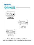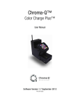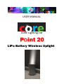
1
USER MANUAL
CORE Lighting Ltd
LiPo Battery Wireless Uplight
Change History
Ver.
Released
Comments
0_1
1_0
22 Sep 10
14 Nov 10
Full Production Release
©CORE Lighting Limited 2010
2
Contents
1.
2.
3.
Technical Features .......................................................................................................................... 1
1.1.
LIGHT HEAD ......................................................................................................................... 1
1.2.
POWER SOURCE & CHARGING ............................................................................................ 1
1.3.
USER CONTROL ................................................................................................................... 2
1.4.
WIRELESS INTERFACE .......................................................................................................... 2
1.5.
MECHANICAL....................................................................................................................... 2
LIGHT HEAD ..................................................................................................................................... 3
2.1.
LIGHT HEAD ......................................................................................................................... 3
2.2.
OPTICS ................................................................................................................................. 3
2.3.
LED COLOUR PERFORMANCE & LIFESPAN .......................................................................... 3
POWER SOURCE & CHARGING ........................................................................................................ 4
3.1.
Battery................................................................................................................................. 4
3.2.
Power Supply Unit (PSU) ..................................................................................................... 4
3.3.
Battery Charging & Discharging .......................................................................................... 4
CHARGING ....................................................................................................................................... 4
DISCHARGING.................................................................................................................................. 5
LIFESPAN ......................................................................................................................................... 5
3.4.
Battery Temperature .......................................................................................................... 5
4.
USER INTERFACE & MENU OPTIONS............................................................................................... 6
4.1.
On/Off ................................................................................................................................. 6
4.2.
MODE .................................................................................................................................. 6
4.2.1.
MODE SELF .......................................................................................................................... 6
SELF COLOUR Option ...................................................................................................................... 6
SELF CYCLE Option .......................................................................................................................... 7
4.2.2.
MODE MSTR ........................................................................................................................ 7
5.
6.
4.2.3.
MODE SLV ........................................................................................................................... 7
4.3.
Brightness Control “BRI%” .................................................................................................. 8
4.4.
“BAT” Battery status Mode ................................................................................................. 8
4.5.
DISP TIME ............................................................................................................................ 9
4.6.
SET PIN ................................................................................................................................ 9
4.7.
DIAGnostics ......................................................................................................................... 9
4.8.
LOCK ON/OFF ...................................................................................................................... 9
WIRELESS INTERFACES .................................................................................................................. 11
5.1.
W-DMX Receive ................................................................................................................ 11
5.2.
W-DMX Transmit............................................................................................................... 11
5.3.
WiFi Control ...................................................................................................................... 11
MECHANICAL................................................................................................................................. 13
©CORE Lighting Limited 2010
3
6.1.
Antenna ............................................................................................................................. 13
6.2.
Locking .............................................................................................................................. 14
7.
Warranty ....................................................................................................................................... 14
8.
Compliance Information ............................................................................................................... 15
8.1.
System Compliance ........................................................................................................... 15
8.2.
FCC & Industry Canada Statement for Radio Compliance ................................................ 15
8.2.1.
WiFi ................................................................................................................................... 15
8.2.2.
W-DMX Transmitter & Receiver ....................................................................................... 16
8.3.
WEEE & RoHS Statement .................................................................................................. 17
ANNEX 1 – Menu Structure................................................................................................................... 18
Please read this entire manual before using the equipment. Please
keep the manual in a safe place so you can refer to it in the future.
Safety:
Connection, installation and mounting of this equipment must be
performed in accordance with all local, regional and national safety
codes and regulations.
Note: Restrictions apply to flying with this equipment due to the
capacity of the cells being greater than 5Ah. Please consult CORE
Lighting for further information.
©CORE Lighting Limited 2010
4
1. Technical Features
•
•
•
•
•
•
•
•
•
•
•
•
Highly efficient RGB + White LEDs producing 2100 lumen output
Ideal for uplighting, colour-wash or high lighting applications
Minimal maintenance during rental use – rugged and intuitive
Sealed to IP65 for indoor and exterior use
16-20h battery life exceeding 7h for most applications
Higher capacity battery upgrade to more than 12h
Attractive full white with shades of off-white
Full recharge less than 3 hours from flat (LiPo Technology)
Wireless DMX control with master/slave operation
WiFi remote control using most WiFi enabled mobile devices with browser
Intuitive & simple operation – designed for repeated rental
Removable polished steel light shroud or custom colour
1.1.LIGHT HEAD
•
•
•
•
•
•
•
•
RGBW Colour Mixing Head using Cree and Seoul Semconductor high-brightness LED chips
Strongly saturated colours, mixed using optic lenses with uniform colour rendering
LED Lumen Output 2100lm matching market-leading mains-powered units
More than 4.2Bn colour shades, including hues of white, by using 4-colour channels
Ability to replicate warm & cool colour temperatures of white light
Standard 10° beam angle. Simple optic replacement with beam angles 30°, & 60° (medium &
wide angles). Others available 10°, 20°, 40°, 50°, 80° plus oval diffusers
Head swivels vertically to allow fine adjustment of beam direction
Thermally designed for LED Lifespan > 50,000 hours (6 years if permanently switched on)
1.2. POWER SOURCE & CHARGING
•
•
•
•
•
•
•
•
•
•
Two power options of mains or battery power
Built-in power supply unit. Input range 90-264VAC 47/63Hz with industry-standard PowerCON
Base “kettle” connector for power within flight case or PowerCON connection to 13A plug
Battery type 14Ah Lithium Polymer (LiPo) with upgrade to higher density 22Ah LiPo pack
Continuous battery operation on dropout of mains supply
Ability to operate the unit and charge battery simultaneously
Smart built-in charger to >95% in 3 hrs (14Ah) or 5hrs (22Ah). Voltage & current monitoring
prevents over-charging
Battery compartment temperature monitored with automatic thermal cut-out
Deep discharge of battery monitored and prevented using smart relay control
Battery operating temperature capability of -20 to +50degC
©CORE Lighting Limited 2010
1
1.3.USER CONTROL
•
•
•
•
•
•
•
Control from Wireless DMX (WDMX – Wireless Solutions), keypad or upgrade to WiFi interface
Onboard control with LED displays visible in dark or bright sunlight
enabling control of all functions including internal colour and fade sequences
Simple intuitive controls. Helpful for untrained staff.
Set of pre-programmed colour & fade sequences.
Upgradeable setup from any device with WiFi and web browser (eg mobile, iPhone, laptop or
PDA). (Note due to security on certain mobiles this facility is blocked on those phones)
Password security protection of interfaces from unauthorised access
Simple built-in diagnostic routines to improve turnaround time in the warehouse environment
1.4.WIRELESS INTERFACE
•
•
•
•
•
•
Each light responds to wireless W-DMX commands as a slave
W-DMX antenna - connection of slave units to a lighting desk or a POINT20/30 unit with Master
capability
Upgradeable W-DMX Master will control a set of slave lights as a stand-alone light network
Upgrade to WiFi (802.11b/g) interface to set up individual lights
WiFi access controller within the unit acts as a web server accessed with an individual IP address
All wireless capabilities are internally integrated, not external add-ons
1.5.MECHANICAL
•
•
•
•
•
•
•
•
Aluminium fabricated housing with black powdercoat finish.
Replaceable stainless steel shroud – painted spares options available in many RAL colours
Stable base unit for uneven surfaces
IP Rating 65 (Totally protected against dust and low pressure water jets from any direction)
W-DMX antenna built into top LED electronics board
Securing hole on top and bottom plates allow padlock to be inserted for security
Weight approx 6.7Kg.
Dimensions 328mm height x 174mm diameter
©CORE Lighting Limited 2010
2
2. LIGHT HEAD
2.1.LIGHT HEAD
The light head may be tilted to any position vertically up to +/-45 degrees for up-lighting or
spotlighting. A Nylok nut on each side of the head bridle assembly allows the swivel tension to be
adjusted.
2.2.OPTICS
The unit is fitted as standard with a clear polycarbonate lens allowing 10 degree beam angle using 7
LED colour-mixing optics. Beam angles of 30° and 60° (medium and wide angle) are available as an
upgrade kit to the standard unit. The diffusers are extremely efficient with >90% transmission
efficiency.
Diffusers are built into the polycarbonate lens in front of the LED mixers allowing them to be
changed by removing the 4mm caphead screws around the outside. These screws must always be
replaced with similar type to prevent damage to the top plate. The screws must not be overtightened as this will damage the polycarbonate lens. When replacing lenses, care must be taken
to ensure dirt is removed from the gasket material and head to ensure water tightness.
Beyond the standard range of diffusers the following beam angles are available by special request:
10°, 20°, 40 & 80°. Elliptical versions are also available (eg 30° x 5°).
2.3.LED COLOUR PERFORMANCE & LIFESPAN
Quality of colour is seen as a critical feature that has been built into this unit.
The LED range, the colours within the range and “binning” options have been selected very carefully
to provide possibly the best colour saturation available. This extends the extreme colour points
available on the colour triangle and therefore extends the number of possible colour combinations.
White LEDs are selected as “neutral white” to maximise its use in combination with the Red, Green,
Blue. White can be made warmer by adding red and green combinations, or cooler by adding blue.
Update rate for the LED’s is a fast 488Hz. The resolution for colour change is 13bits providing a very
smooth dimming curve. This fast combination makes the units capable of lighting in TV work.
The head’s thermal design and correct current balancing through LED chains ensures that LED life
should exceed 50,000 hours. Significant effort has been made to ensure correct thermal design to
achieve this.
©CORE Lighting Limited 2010
3
3. POWER SOURCE & CHARGING
3.1.Battery
The battery is a 12 Volt lithium polymer (LiPo) battery pack. The standard pack is 14Ah but an
upgrade to 22Ah is also available that increases battery life by approximately 50%.
Note: Restrictions apply to flying with this equipment due to the capacity of the cells being greater
than 5Ah. Please consult CORE Lighting for further information.
3.2.Power Supply Unit (PSU)
The unit may be operated under battery power or power supplied by mains electricity using the
cable provided (mains input to PowerCON connector). Alternatively the unit may be inserted onto a
charging base with the “kettle” connector.
The power input range is 90-264VAC at 47-63Hz so may be used worldwide.
The electronics switches its power source based on the greater voltage of either power supply or
battery, so if the mains power is removed (in a power cut or generator failure) the PSU voltage drops
to 0 so the unit will switch over to battery power.
If both base connector and PowerCON are connected to mains at the same time the base connector
takes precedent. The PowerCON connector is then disabled so any live connections are removed.
The same occurs in reverse so that a connection to PowerCON removes live connections from the
base connector.
3.3.Battery Charging & Discharging
CHARGING
Simply plug the mains connector into the wall or place onto the charging base using the bottom
connector. The unit manages its own charging so it may be left connected to mains permanently.
However, the battery specification provides that 95% of charge is maintained over 3 months.
Voltage of the battery can be seen in one of the menu options, achieving full charge at
approximately 13.8V (at 20°C). This will fall approximately to 12.5-12.8V once the charging lead has
been removed. The charging current can also be monitored (see DIAGnostics menu ‘AN1’) and
should be around 5 Amps on full-charge, falling when the battery is near capacity. The charging LED
on the keypad (lower right) and LEDs in the head will flash red whilst charging takes place and a “^”
symbol will appear in the BATT menu option. As it nears capacity red will turn to amber. When the
battery is full the charging LED will turn green.
©CORE Lighting Limited 2010
4
Normal charging achieves >95% of battery level in under 2.5 hours. The unit continues charging after
this point, approximately 3-4 hours in total to complete charging when “BATT FULL” is displayed in
that menu option. The unit moves to trickle-charge mode indefinitely which is useful for maintaining
charge whilst units are in hire stock. “BATT FULL” is usually seen when charge current drops to 0.2A
(see DIAGnostics menu ‘AN1’).
The power supply can charge the battery and operate the unit simultaneously, although this takes
longer to charge as less current can be drawn by the charger from the PSU.
Note – when charging the head LEDs are disabled and are converted to a charging operation
display. Normal operation can be resumed by pressing the “ON” button.
DISCHARGING
Discharge lasts in excess of 7 hours in a normal colour-cycling mode “SLOW RNBW” at full
brightness. In practice the unit will achieve longer life at normal operating temperatures providing
the charging regime is maintained as described above. Life may be extended by reducing the LED
brightness control to, say, 70% which will add 30% to life.
If full white is used then lifetime will be considerably reduced, although the LEDs produce over 2100
lumens in this mode. Setting to 50% brightness will achieve more than double the lifespan.
When the battery drops to a particular voltage the low battery red LED is activated permanently on
the lower right of the membrane keypad as a warning the battery needs recharging. When the
voltage drops further the unit simply switches off. This is to prevent over-discharge as a LiPo battery
can go into a non-recoverable mode in such a case. Smart monitoring of both the charge and
discharge cycles therefore helps to preserve the lifetime of the battery.
LIFESPAN
Once discharged it is important for the battery to be recharged as soon as possible to prevent long
term damage to the battery. The battery should be capable of more than 300 recharge cycles if fully
discharged then fully recharged straight away. Lighter use will preserve battery life further.
3.4.Battery Temperature
This may be monitored in the “BATT” menu option and is monitored by software so that excessive
heat shuts down the unit over-charging. A steady flashing red charge status LED indicates this has
occurred.
The battery is capable of operation -20 to +50 deg.
©CORE Lighting Limited 2010
5
4. USER INTERFACE & MENU OPTIONS
PLEASE REFER TO ANNEX 1 MENU STRUCTURE FOR DETAIL ON HOW TO STEP THROUGH MENU
OPTIONS.
4.1.On/Off
The unit is switched ON, either on mains or battery power, by pressing the silver button on the top
plate of the unit.
The unit is switched OFF – but only disconnected from the battery - by pressing the RED switch on
top of the unit. On mains power this red button will not switch off the unit.
To switch off mains power the power cord should be disconnected at the wall or by rotating the
PowerCON connector through 45 degrees anticlockwise.
After the unit is switched off, when reactivated with the “ON” switch the lighting unit will retain its
previous state prior to shutdown.
4.2.MODE
The unit enters this menu option upon switch-on. Three modes are available on the unit:
• Self-functioning using the on-board keypad and display or upgradeable to WiFi.
• Master unit controlling others (Wireless DMX) [Wireless is an upgrade option].
• Slave unit controlled by a Master unit (Wireless DMX) or a lighting desk.
4.2.1. MODE SELF
Two options are available within this mode: “SELF COLR” and “SELF CYCL”. These functions are also
available through WiFi on upgraded units.
“MODE SELF” is for self-contained units not needing to be linked to other units or lighting desks and
is suitable for many applications. In reality if multiple units are adjacent to each other and colour
cycling functions are selected then providing they are switched on simultaneously the clock accuracy
should maintain their synchronisation reasonably closely.
Note the brightness of both options may be controlled using the BRI% function. It will help
preserve battery life if lower brightness is selected.
SELF COLOUR Option
This allows individual colours to be controlled on the unit menu from values of 0 to 255. This
provides around 4.2 billion combinations including easily definable shades of white.
©CORE Lighting Limited 2010
6
SELF CYCLE Option
This mode sets the unit to cycle through various colours depending on the mode. Provision has been
provided for all colour cycling, warm options or cool options and a couple of different speeds.
The most popular is “SLOW RNBW” for a gradually changing colour sequence of all colours, which
shows off the true colour depths of the LEDs. “TEST” switches between the four colour chains of
LEDS so the individual elements within each colour chain can be seen and checked.
4.2.2. MODE MSTR
This mode is available on the menu but the enabling hardware is available as an upgrade option. It
allows the unit to be configured as a MASTER in a DMX universe and eliminates the need for a
lighting desk for a simple lighting setup. Other SLAVE units set in MODE SLV will respond to DMX
signals output from this MASTER device. MASTER mode has built-in patterns of lights allowing each
SLAVE to replicate the colour changes of the MASTER Unit, thus creating a wider lighting scheme
using a network of lights that are synchronised together.
It is possible to set the output of MASTER mode to send via wired communications (OUT DMX) or
using a built-in Wireless Solutions W-DMX transmitter (OUT WDMX) if this option has been
purchased.
SLAVE units will need to be connected to the MASTER unit. This can be achieved by selecting the
“ADD UNIT” in the MASTER DMX menu. Prior to this the SLAVE unit needs to have its wireless
disconnected from any other transmitter by entering “WDMX UNLNK”. This also puts the SLAVE into
“hunting” mode where it will seek a new MASTER unit. When the unit comes into contact with a
master unit in “ADD UNIT” mode, the two units will automatically pair together after a few seconds.
During this process a decimal point will flash quickly in the bottom right corner of the display
simultaneously on both Master and Slave units. When this extinguishes and becomes statically “on”
then pairing is complete. Any number of slaves can be connected to a single Master unit in this way
at the same time by setting all Slaves into “Unlink” mode then adding them with a single “Add Unit”
entry on the Master unit.
4.2.3. MODE SLV
SLAVE mode is fitted and can be configured to work through Wired DMX512 or Wireless-DMX (“IN
DMX” or “IN WDMX” respectively).
Wired DMX512 uses the male XLR connector on the rear for connection to any lighting desk or
equipment conforming to DMX512 protocol.
WirelessDMX uses a module from Swedish firm Wireless Solutions with a built-in antenna within the
housing exterior.
©CORE Lighting Limited 2010
7
LINKING & UNLINKING to a Wireless Solutions Transmitter
The POINT20 needs to be linked to the transmitter being used, which is a simple process. But first
the unit needs to be Unlinked from any previous unit it was “paired” with.
In the menu, the “Unlink” function follows from the IN menu that follows MODE SLV. The input
selection is either DMX or WDMX. Pressing enter takes you to a menu showing WDMX ULNK. Press
enter at this stage and the unlinking happens (note: it takes 5 seconds or so). After pressing enter,
the unit returns to the MODE select menu. If you don't want to unlink, then press MENU UP or
MENU DOWN and it will take the unit to the MODE menu without unlinking.
When the unit is unlinked, adding it to a Wireless Solutions transmitter box is just a matter of
pressing the button on the transmitter box for a brief period (less than 3 seconds). The lamps will
pick up after about 5 seconds and the SLAVE will show a decimal point statically illuminated in the
display.
4.3.Brightness Control “BRI%” and “LEVL 1” to “LEVL3”
The LEVL brightness level setting sets the overall dimmer for the unit for all SELF operating, SLAVE
and MASTER modes (i.e. self or external control). BRI% then allows further control once this is set.
LEVL1 sets the overall brightness of the unit to 125%.
LEVL2 sets overall brightness to 100%
LEVL3 is 66%.
Normal operating mode is LEVL2 which should give over 7-8 hours life on a normal colour cycle.
LEVL1 can be regarded as a ‘turbo boost’ mode to provide extra brightness is needed, such as
architectural building lighting where additional light throw is required. LEVL3 can be regarded as a
battery preservation mode to gain approximately 30% extra lifetime from a charge.
BRI% adjusts the brightness as a multiplier of the colour options in “MODE SELF” or “MODE MSTR”
and is selected as a percentage 0 to 100. It is a useful tool for conserving battery life also. This should
be set to 0 whilst charging to prevent unnecessary drain on the power supply and to optimise
charging.
4.4.“BAT” Battery status Mode
Two options are available: one showing temperature of the battery compartment used as a failsafe
mechanism to prevent damage through over-charging. The second shows battery voltage.
Note the symbol “^” shows battery charging is active. “BATT FULL” shows when this is complete.
©CORE Lighting Limited 2010
8
4.5.DISP TIME
The keyboard display is extinguished after a fixed period of keypad inactivity in order to eliminate
glare. This function sets the time delay from last key operation between 30 and 300 seconds before
the display switches off. A reminder point is left switched on (bottom right of left display), enabling
the user to see the unit is switched on when the LED head brightness is turned to zero and is running
on battery power. This minimises the possibility of the unit being left on battery power indefinitely
without any indication.
4.6.SET PIN
The default Personal Identification Number (PIN) to unlock the unit after it has been placed in
“LOCK” mode is “2673”. The PIN number may be altered using this function by entering the old PIN
number for security then entering the new PIN number. The entry needs to be repeated to ensure
no errors are made. The +/- keys are used to make the adjustment on each character and the enter
key is used to jump from one character to the next.
If the PIN number is forgotten then the value for AN16 in the Diagnostics menu should be reported
to CORE Lighting, who will explain the PIN unlocking procedure.
4.7.DIAGnostics
Allows the factory to check various functions that will be used in the self-test sequence. The
following are worthy of note:
AN1 – Battery Current showing either charging current or useage current.
AN4 – Battery Temperature, also available in “BAT” menu
4.8.LOCK ON/OFF
If the LOCK ON function is selected then the data entry to the system is locked to prevent tampering.
The full menu can still be seen using key presses but no changes can be made. LOCK ON is retained if
the unit is switched off then back on again.
To regain control of the unit the Unlock function should be selected by selecting “LOCK OFF” and
pressing Enter. The PIN Code to unlock the unit is set at the factory to “2673” – characters
represented as “CORE” on a standard telephone keypad.
This may be changed by entering the SET PIN menu option (Section 4.6).
©CORE Lighting Limited 2010
9
4.9.SHOW S/N Serial Number
This is the serial number of the unit (eg “CORE 0216”) and provides the WiFi SSID address based on
the unique serial number (its WiFi unique identity). The number is set at the factory and is unique to
each unit.
4.10.
WIFI Status
WiFi (where fitted as an upgrade) may be activated by selecting “WiFi ON” in the menu and pressing
the “enter” key. When the counter reaches “3” the unit is ready to receive WiFi requests. The display
will remain in this state and cannot be adjusted from this point using the keypad except for
switching WiFi off.
Switching off is a matter of entering “WiFi OFF” then “enter”. Note the importance of hitting the
“enter” key. WiFi is not shipping as a production upgrade at the time of writing but will be available
soon.
4.11.
ADDR DMX Address
This is the address channel for either wireless DMX or Wired DMX512.
Channels 1 to 506 may be selected, although from the selected channel the subsequent 5 channels
are then allocated as below.
Each 5 steps represents the following order of channels:
RED
GREEN
BLUE
WHITE
BRIGHTNESS
Values of 0 to 255 may be input to each of those channels.
NOTE –A VALUE MUST BE USED FOR BRIGHTNESS, OTHERWISE NO LED OUTPUT WILL BE
OBTAINED FROM ANY OF THE COLOURS (Brightness x Colour Value = light output).
©CORE Lighting Limited 2010
10
5. WIRELESS INTERFACES
The Point30 Unit uses Wireless Solutions W-DMX protocol for receiving and sending wireless DMX
data. There are 512 channels of which the unit uses five. WiFi Control is also available to replace
local control from the keypad with remote control from devices with a WiFi interface and browser
software built-in.
5.1.W-DMX Receive
A W-DMX Receiver is built into every unit thus enabling it to operate in SLAVE mode. See Section
4.2.3 for operational details.
When linked to a Wireless Solutions transmitter or CORE POINT30 MASTER unit (an upgrade option)
the units have a static “link” LED in the bottom right hand side of the display to show that a W-DMX
connection has been made. When hunting for a transmitter this will be extinguished but will flash
quickly when detected by a transmitter hunting for receivers. Once the transmit and receive devices
establish the connection the LED stops flashing showing they are now linked.
5.2.W-DMX Transmit
A W-DMX Transmitter (MASTER Mode) is available as an upgrade option within the unit. See Section
4.2.2 for details on how to operate the unit in this mode.
5.3.WiFi Control
WiFi control is an upgrade option and is suitable for use with devices allowing ad-hoc networking
(note this excludes RIM Blackberry devices at the time of writing). The WiFi module within the unit
acts as a web server and may be accessed by finding the unit in the WiFi networks as “CORE XXXX”
from the client device such as PC, PDA or mobile phone with WiFi and browser (this is the SSID). The
web server facility allows many complex functions to be achieved not possible on the keypad, such
as colour-picking static colours using a colour chart. Diagnostic information is also available from the
unit. If the W-DMX Transmit upgrade option is fitted then it is possible to use WiFi to control the
MASTER unit which can then control many SLAVE units. This is useful when setting up a lighting
scheme.
Select the unit showing the correct CORE SSID in WiFi networks on the host device.
Enter the WEP password key which is “w2673” 0r “w” followed by “CORE” on a standard telephone
keypad.
©CORE Lighting Limited 2010
11
Once logged into the unit, select the web browser and enter into the URL address bar
‘http://169.254.100.1/’. This should bring up a number of tabs and a logical workflow within each
tab.
In addition to the above procedure, on an Apple iPhone or iPod Touch the WiFi connection for the
CORE device needs to be set with a Static IP address and settings as follows – by clicking on the right
arrow on the relevant WiFi connection, clicking the “Static” tab and entering the settings as follows:
IP Address: 169.254.100.2
Subnet Mask: 255.255.0.0
Router: 169.254.100.1
DNS: no settings to be entered
©CORE Lighting Limited 2010
12
6. MECHANICAL
6.1.Dimensions
©CORE Lighting Limited 2010
13
6.2.Antenna
The antenna is a high-gain type similar in performance to the Wireless Solutions W-DMX 2dB
standard antenna according to testing. This antenna is now fitted to all CORE POINT20&30 units.
6.3.Locking
The unit may be locked to a nearby object by passing a locking wire or padlock through the locking
holes in the top or bottom plates.
7. Warranty
CORE Lighting Limited (CORE Lighting) warrants this product to be free from defects in materials and
workmanship (subject to the terms set forth below).
CORE Lighting will repair or replace (at CORE Lighting's option) this product or any defective parts in
this product. The standard warranty period is 12 months from date of purchase although this period
may vary from country to country. If in doubt consult your dealer and ensure that you retain proof of
purchase.
To obtain warranty service, please contact the CORE Lighting authorised dealer from which you
purchased this product. If your dealer is not equipped to perform the repair of your CORE Lighting
product, it can be returned directly to CORE Lighting, with carriage being paid at your own expense.
You will need to ship this product in either its original packaging or packaging affording an equal
degree of protection. Providing the product is found to be faulty, CORE Lighting will pay for return
carriage.
Proof of purchase in the form of a bill of sale or receipted invoice, which is evidence that this
product is within the warranty period, must be presented to obtain warranty service.
This Warranty is invalid if (a) the factory-applied serial number has been altered or removed from
this product or (b) this product was not purchased from a CORE Lighting authorised dealer.
This Warranty does not cover cosmetic damage or damage due to acts of God, accident, misuse,
abuse, negligence, commercial use, or modification of, or to any part of, the product. This Warranty
does not cover damage due to improper operation, maintenance or installation, or attempted repair
by anyone other than CORE Lighting or a CORE Lighting dealer, or authorised service agent which is
authorised to do CORE Lighting warranty work. Any unauthorised repairs will void this Warranty.
This Warranty does not cover products sold AS IS or WITH ALL FAULTS.
REPAIRS OR REPLACEMENTS AS PROVIDED UNDER THIS WARRANTY ARE THE EXCLUSIVE REMEDY OF
THE CONSUMER. CORE LIGHTING SHALL NOT BE LIABLE FOR ANY INCIDENTAL OR CONSEQUENTIAL
DAMAGES FOR BREACH OF ANY EXPRESS OR IMPLIED WARRANTY IN THIS PRODUCT. EXCEPT TO THE
©CORE Lighting Limited 2010
14
EXTENT PROHIBITED BY LAW, THIS WARRANTY IS EXCLUSIVE AND IN LIEU OF ALL OTHER EXPRESS
AND IMPLIED WARRANTIES WHATSOEVER INCLUDING, BUT NOT LIMITED TO, THE WARRANTY OF
MERCHANTABILITY AND FITNESS FOR A PRACTICAL PURPOSE.
Some countries and US states do not allow the exclusion or limitation of incidental or consequential
damages or implied warranties so the above exclusions may not apply to you. This Warranty gives
you specific legal rights, and you may have other statutory rights, which vary from state to state or
country to country.
For any service, in or out of warranty, please contact your dealer.
8. Compliance Information
8.1.System Compliance
CORE Lighting Limited declares that this product conforms to the specifications listed in this manual,
following the provisions of the European R&TTE directive 1999/5/EC:
Restrictions on Hazardous Substances (RoHS) (2002/95/CE)
Electromagnetic Compatibility (2004/108/EC).
Safety (EN 60950)
Technical requirements for radio equipment. (EN 300 328)
CAUTION—This equipment is intended to be used in all EU and EFTA countries.
Outdoor use may be restricted to certain frequencies and/or may require a license for operation.
Contact local Authority for procedure to follow.
8.2.FCC & Industry Canada Statement for Radio Compliance
8.2.1. WiFi
A CORE POINT30 unit which has been upgraded with WiFi functionality contains Transmitter Module
FCC ID: PI405W.
This device complies with part 15 of the FCC Rules. Operation is subject to the following two
conditions: (1) This device may not cause harmful interference, and (2) this device must accept any
interference received, including interference that may cause undesired operation.
Changes or modifications not expressly approved by the party responsible for compliance could void
the user's authority to operate the equipment.
The antennas for this transmitter must be installed to provide a separation distance of at least 20
cm from all persons and must not be co-located or operating in conjunction with any other antenna
or transmitter.
©CORE Lighting Limited 2010
15
8.2.2. W-DMX Transmitter & Receiver
We,
CORE Lighting Limited
Red Lion House
St Mary’s Street
Painswick
Gloucestershire GL6 6QG
declare under our sole responsibility that the product
FCC ID: UQT-WDMXOEMPCBF
Model: W-DMX OEM PCB F
complies with Part 15 of the FCC Rules.
Operation is subject to the following two conditions:
(1) this device may not cause harmful interference, and
(2) this device must accept any interference received, including interference that may cause
undesired operation.
To assure continued compliance, any changes or modifications not expressly approved by the party
responsible for compliance could void the user's authority to operate this equipment.
NOTE: This equipment has been tested and found to comply with the limits for a Class B digital
device, pursuant to Part 15 of the FCC Rules. These limits are designed to provide reasonable
protection against harmful interference in a residential installation.
This equipment generates, uses, and can radiate radio frequency energy and, if not installed and
used in accordance with the instructions, may cause harmful interference to radio communications.
However, there is no guarantee that interference will not occur in a particular installation. If this
equipment does cause harmful interference to radio or television reception, which can be
determined by turning the equipment off and on, the user is encouraged to try and correct the
interference by one or more of the following measures:
• Reorient or locate the receiving antenna.
• Increase the separation between the equipment and receiver.
• Connect the equipment into an outlet on a circuit different from that to which the receiver is
connected.
• Consult the dealer or an experienced radio/TV technician for help.
RF Exposure Warning for North America, and Australia
Warning! To meet FCC and other national safety guidelines for RF exposure, the antennas for this
device must be installed to ensure a minimum separation distance of 20cm (7.9 in.) from persons.
©CORE Lighting Limited 2010
16
8.3.WEEE & RoHS Statement
The European Directive 2002/96/EC on Waste Electrical and Electronic Equipment (WEEE), requires
that products must not be disposed of the normal unsorted municipal waste stream. Appliances
must be collected separately in order to optimise the recovery and recycling of the materials they
contain and reduce the impact on human health and the environment.
The consumer must contact their local authority or retailer for information concerning disposal of
their products.
CORE Lighting provides a take-back facility for batteries used within CORE Lighting products,
although the expense for transport remains the liability of the consumer. Please contact CORE
Lighting directly if this service is required.
©CORE Lighting Limited 2010
17
ANNEX 1 – Menu Structure
See attached sheet
©CORE Lighting Limited 2010
18