1
RUGGEDCOM WiN7200
Installation Guide
Chapter 4
Installation Procedures
1. Cover the Console port (only used for maintenance purposes by authorized personnel). See Section 4.5.1,
“Cover the Console Port”.
2. Assemble the PoE connector. See Section 4.5.2, “Assemble the PoE Connector”.
3. Assemble the base station mounting bracket. See Section 4.5.3, “Attaching the Mounting Bracket”.
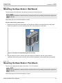
4. Mount the base station to a wall or pole. See Section 4.5.4, “Mounting the Base Station: Wall Mount” and
Section 4.5.5, “Mounting the Base Station: Pole Mount”.
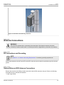
5. Complete the antenna connections and grounding. See Section 4.5.6, “Antenna Connections”.
6. Connect the base station Data Adaptor. See Section 4.5.7, “Connecting the Base Station Data Adaptor”.
7. Perform the initial base station setup. See Chapter 5, Setup.
Section 4.5.1
Cover the Console Port
The Console port is only used for maintenance operations performed by authorized service personnel. It should
be closed with the attached cover in normal conditions.
NOTE
See Appendix D, Console Connector Specifications for information on the console cable pinout.
Section 4.5.2
Assemble the PoE Connector
Follow these steps to assemble the The CD/ETH connector for the Power over Ethernet (PoE) connection.
Procedure: Assembling the PoE CD/ETH Connector
1.
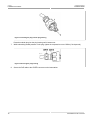
Push the connector housing parts to the end of the Ethernet cable.
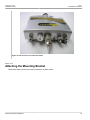
Figure 6: Installing PoE/Ethernet Connector Parts on the Ethernet cable
2.
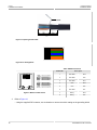
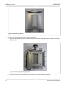
Refer to Figure 7 and Figure 8.
• Strip at least 22mm (0.71 inch) of sheathing from the end of the cable.
• Remove the inner jacket and foil, leaving 10mm (0.25 inch) of inner jacket and the drain wire.
• Fan the pairs into the proper color code and trim the conductors, leaving 12mm (0.47 inch) extending from
the inner jacket.
Cover the Console Port
15