1
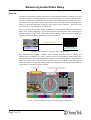
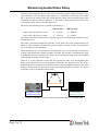
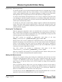
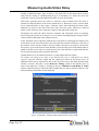
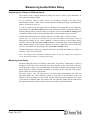
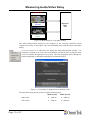
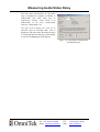
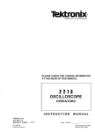
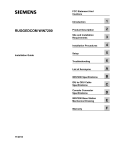
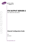
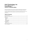
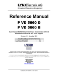
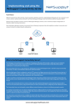
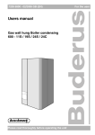
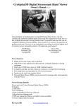
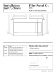
www.omnitek.tv
IMAGE PROCESSING TECHNIQUES
Measuring Audio/Video Delay
With the right software options and the right setup, Audio/Video Delay (a.k.a. Lip-Sync
Delay) can be measured both on OmniTek’s recent OTM/OTR series of Waveform Analysers
and on the company’s earlier ‘Classic’ XR, TQ, LAB and PQA systems. Measurements can
be made on SD, HD or (with an OTM or OTR) 3Gb/s SDI video signals, and can cover
delays that apply to either PCM-embedded audio or Dolby-encoded audio as appropriate.
While the details of the options and displays used differ for the different analysers, the same
basic method is used on all the systems.
This application note explains the approach that is taken in making these measurements and
the setup that is required (including the software options that are needed). It also describes
how similar steps may be used to measure the timing of a video signal relative to a selected
reference signal, how to measure the delay between signals fed into different inputs, and how
to measure the delay introduced by a signal path (a.k.a. Loop Delay).
23 January 2012
APPLICATION NOTE
Measuring Audio/Video Delay
Overview
In general, the transmission path along which an SDI signal travels delays both the video and
the audio elements of an SDI signal but not to the same degree. As a result, while the audio
and video components are probably in sync at the start of their transmission path, they won‟t
necessarily be in sync where they are delivered at the end of the transmission path. This
effect is particularly noticeable where the video shows people speaking – hence the term
„Lip-Sync Delay‟ for the difference in the delays.
The way in which the Lip-Sync Delay is measured is by transmitting along the transmission
path a video signal comprising a special Test Sequence, the audio and video components of
which are known very precisely. At the end of the transmission path, the signal is fed into the
appropriate OmniTek Delay Measurement system for analysis.
Transmission Path
Test Sequence source
(OTM/OTR/OmniTek LAB)
OmniTek Delay
Measurement System
Figure 1: Basic setup for Lip-Sync Delay measurement.
The OmniTek Test Sequence contains many elements that are useful for testing and
analysing the performance of a video system, however for the purposes of the audio/video
delay measurement it has two characteristics that are of special importance – an embedded
audio tone (in the case of the PCM-only sequence, this tone is added by the generator on
which the sequence is run) and a binary frame count displayed in the top left-hand corner of
each frame as a sequence of yellow squares.
This gives a binary count of
the test sequence
When the clock hand reaches the top (frame 0), an
audio pulse is generated for 1 frame duration
Figure 2: The Test Sequence with its special properties highlighted.
Page 2 of 12
Measuring Audio/Video Delay
The Delay Measurement System on the various OmniTek systems analyses the input video
signal looking for the first frame in the sequence (as identified by the binary code). When
this is detected, an internal timer then counts the time delay before the audio input pulse
associated with the first frame is detected, i.e. the relative delay between the arrival of the
video and the audio. The result is then displayed.
The delay range that the system is capable of measuring is:
50Hz Systems
60Hz Systems
Audio early with respect to video:
0 ~ 5760 ms
0 ~ 4800 ms
Video early with respect to audio:
0 ~ 1920 ms
0 ~ 1600 ms.
The relative time delay measurement is typically expressed in milliseconds, and the accuracy
is better than 1 ms.
The effect a particular transmission path has on the audio and video elements differs for
different video standards, and OmniTek provide separate versions of their Test Sequences
for use at different video standards.
When running the test, it is important to ensure that the correct version of the Test Sequence
is being used and that the complete sequence is loaded. The test that is conducted also needs
to distinguish between measuring the effect of the transmission path on PCM-embedded
audio and that on Dolby-encoded audio.
However, it is also important to note that the transmission paths over which audio/video
delays can be measured are not just limited to links made over physical wires. The device
transmitting the Test Sequence (of which more anon) may be installed remotely to the video
analyzer, which means it is possible to use the same basic procedure to measure A/V delays
in satellite, cable or terrestrial broadcast links.
Transmission Path
Test Sequence source
(OTM/OTR/OmniTek LAB)
OmniTek Delay
Measurement System
Figure 3: Setup for a Lip-Sync Delay measurement made over a satellite link.
Page 3 of 12
Measuring Audio/Video Delay
Equipment Needed
The equipment needed in carrying out audio/video delay measurements divides into two
groups: the equipment used to generate the special Test Sequence signal; and the Delay
Measurement System.
Equipment for Generating the Test Sequence
The source files for the Test Sequences are provided in two main forms:
1. As sets of 192 YUV files, to which there needs to be added an audio click coincident
with Frame 1 of the sequence. The basic Test Sequence used here is referred to as Test
Sequence A.
2. As 100-frame long ‘RVF’-format files, with an uncompressed PCM audio tone on
channels 1 & 2 and a Dolby-E encoded tone on channels 3 & 4. RVF is a proprietary
OmniTek file format that comprises a header followed by the raw data from the serial
bitstream. The basic Test Sequence used here is referred to as Test Sequence E.
(There is also a Test Sequence B available for the OmniTek PQA but, while this can be used
for Lip-Sync Delay measurements, its principal role is to identify dropped frames and parity
errors.)
Versions of Test Sequence A and Test Sequence E are available for all supported video standards.
The RVF versions of the Test Sequence may be used to measure any of the following:
•
PCM delay affecting PCM source
•
PCM delay affecting Dolby-E source
•
Dolby-E delay affecting Dolby-E source
•
Dolby-E delay affecting PCM source
This last mode of operation is particularly useful where a PCM source is put through a
Dolby-E encoder as the operation of de-embedding the audio and encoding it often
introduces an unknown delay.
The YUV versions are intended for use with systems that don’t support RVF files to determine
just the PCM delay affecting a PCM source.
The YUV sequences can be played out at SD and HD video standards on an OmniTek LAB
system or at SD, HD or 3Gb/s video standards on any OmniTek OTM or OTR system that
includes the GEN and GEN_MOTION options and the VIDEO_HD, VIDEO_DL or
VIDEO_3G option that covers the video standard at which the sequence is to be generated.
Note: Recent versions of the OTM/OTR software have the VIDEO_HD option automatically
enabled.
The RVF sequences can also be played out either on an OmniTek LAB system or an OTM or
an OTR but further extra software is required. In the case of the LAB, the system also needs
to include the ‘Advanced’ option which allows the generation of video that includes blanking
and other ancillary data from the source RVF file. In the case of an OTM or an OTR, the
system needs to also include the GEN_ADV option.
However, it should be noted that the OmniTek systems are only needed to generate the test signal
from the supplied files. When the test signal is generated, it can be recorded on an appropriate
video recorder and simply played out over the chosen transmission path from there.
Page 4 of 12
Measuring Audio/Video Delay
Equipment for Measuring the Delay
To measure the delay, the end of the transmission path needs to be fed either into one of the
‘Classic’ OmniTek systems (XR, TQ, LAB or PQA) or into an OmniTek OTM or OTR
system. Again, additional options are required depending on whether just the PCM delay
affecting PCM source is being measured or one of the other more complex options.
To measure the PCM delay affecting PCM source on a ‘Classic’ OmniTek system, this needs
to be running the ‘Advanced’ option: to measure it on an OTM or OTR system, this needs to
have the AUDIO option installed. Note: Recent versions of the OTM/OTR software have the
AUDIO option automatically enabled.
To measure any of the more complex delays, Dolby E support is needed in the measurement
system. This means either using an OmniTek XR or TQ with the ‘Advanced Audio’ and
‘Dolby-E’ options, or an OmniTek OTM/OTR system with both the AUDIO option and the
AUDIO_DOLBY_E option.
Running the Test Sequence
With the appropriate equipment in place (as described above), the process of running an
RVF version of the Test Sequence is very straightforward. You simply need to locate a copy
of the version of the Test Sequence appropriate to the video standard that is being used, load
it into the generator in the normal way and play it out.
The RVF versions are provided in subdirectories with names
DolbyE_<NumActiveLines>_[Field|Frame]/RVF_[i|p]<FieldRate>Hz.
of
the
form
Playing out the YUV version is slightly more complicated in that, as well as loading the Test
Sequence and playing it out in the usual way, you also need to add an audio click alongside
Frame 1 of the sequence. How this is done on an OmniTek LAB system is explained in
Section 12 of the OmniTek LAB User Guide; how this is done on an OTM/OTR is explained
in Section N.2 of your OTM/OTR User Guide.
The YUV versions are provided in subdirectories with names of the form
<NumActiveLines>[_<AspectRatio>]_[Field|Frame][_<Frames>]/YUV
Both sets of sequences may already be on your OmniTek LAB or OTM or OTR system, but
they are also available to download from the OmniTek website.
Making the Measurements
With the Test Sequence being played along the transmission path and the end of the
transmission path plugged into either one of the ‘Classic’ OmniTek systems (XR, TQ, LAB
or PQA) or an OTM/OTR system with the appropriate options (see ‘Equipment Needed’
page 4 above), the Lip-Sync Delay can be read off simply by calling up the appropriate
window display.
Where an OmniTek OTM or OTR system is used, the window in which to see the results is
the AV Relative Timing View. This is a member of the TIMING category so can be selected
either from the TIMING section of the View Tile Browser or by pressing the TIMING tile
button on an OTM 1000 or an OTR 1001c (with control panel).
You then need to use the Audio Input button on the associated Button Bar to select the
appropriate audio input and the Pair button to select the channel pair.
Page 5 of 12
Measuring Audio/Video Delay
Figure 4: AV Relative Timing View on an OmniTek OTM or OTR.
The display shows two „meters‟, the upper one showing the difference in timing relative to
the video of the audio in the first channel in the selected channel pair and the lower one
showing this for the second channel in this channel pair. The ends of the meter represent 1
field.
(Further details are to be found in Section N.2 of the OTM/OTR User Guide.)
For the XR, TQ and LAB, the required display is the Delay Measurement window,
represented on the main (Window) toolbar by the two-arrow icon.
Figure 5: Delay Measurement window on the OmniTek XR, TQ and LAB.
Page 6 of 12
Measuring Audio/Video Delay
To display the Lip-Sync Delay affecting PCM embedded audio, use the PCM Delay
option in associated Options menu to select PCM Relative Delay and use the Embedded
Audio option in the same menu to select the channel on which the test is to be run.
To display the Lip-Sync Delay affected Dolby-E audio (XR and TQ only), use the DolbyE Delay option in associated Options menu to select Dolby-E Relative Delay and use the
Dolby-E Audio option in the same menu to select the channel on which the test is to be
run.
The results are then displayed in the appropriate slot of the above display. The figure given
shows the timing of the audio channel (detailed below the bar) relative to the video. The
label below the bar also moves in proportion to the delay being measured (though this
movement is imperceptible where the difference is small).
(Further details are to be found in Section 12 of the OmniTek XR and LAB User Guides and
Section 11 of the OmniTek TQ User Guide.)
The PQA also displays the results through a Delay Measurement window, called up by
clicking the two-arrow icon on the main toolbar. However the display used and the way it is
set-up differs from that on the XR, TQ and LAB.
Figure 6: Delay Measurement window on the OmniTek PQA.
To see what the Lip-Sync Delay is here, you need to:
Set the Sequence type to the type of test sequence that is being used (A or B);
Set the Duration to the number of frames in the sequence; and
Select the Relative page of the display.
(Further details are to be found in Section 12 of the OmniTek PQA User Manual.)
When using these displays, please note that delay calculations are performed once for each
loop around the complete video sequence, so there is a latency of several seconds before new
delay readings are displayed.
Page 7 of 12
Measuring Audio/Video Delay
Determining Timing against a Reference Signal
Lip-Sync Delay is not the only timing measurement that can be made.
For instance, the software on the OmniTek XR, TQ & LAB and that on OTM & OTR
systems also allow you to compare the timing of a video input signal against an external
analog reference signal.
On an OTM or OTR system, the external reference signal is supplied through the Ref Loop
connectors on the rear of the machine. Note: If the reference signal is not being continued
onto other systems, terminate the other BNC on the REF loop with a 75Ω terminator.
Reference
Loop
ANA OUT
SDI OUT2
SDI OUT1
SDI IN2
SDI IN1
Figure 7: Rear view of an OTM 1000 showing the Reference Loop connectors.
The timing of the chosen video signal relative to the external reference can then be seen by
calling up the Reference Timing View (which, like the AV Relative Timing View, is also a
member of the TIMING category).
Figure 8: Reference Timing View on an OmniTek OTM or OTR.
This View comprises three „meters‟, the first of which compares the timing of the Analog
Reference and Input 1, while the the second compares the timing of the Analog Reference
and Input 2; and the third compares the timing of Input 1 and Input 2 (see „Comparing the
Page 8 of 12
Measuring Audio/Video Delay
Timing on Different Inputs‟ page 10 below). The upper line of each meter shows by how
many lines the timing is advanced/delayed (up to a maximum of 1 field); the lower line
refines this count by giving the additional number of pixels in the delay.
Each meter typically shows the extent to which the source named below the meter is
advanced or delayed relative to the source named above it. Where the („lower‟) source under
test is advanced relative to the („upper‟) reference source, bars indicating the extent of this
difference are shown to the left of the centre line; where the source under test is delayed
relative to the reference source, these bars appear to the right of the centre line.
The display also offers the choice between „standard‟ and „line-based‟ forms of reporting,
and of saving the current set of delays as a set of Offsets and displaying the timings relative
to those Offsets rather than to the analog reference.
In the „standard‟ form of reporting, both the line count shown on the upper line and the pixel
count shown on the lower line point in the same direction and the total delay is the sum of
the number of lines and the number of pixels. When „line-based‟ reporting is selected, the
line count is given to the nearest whole number of lines and the pixel count should either be
added to the line count if the two meters point in the same direction or subtracted from the
line count if the meters point in opposite directions.
(Further details are to be found in Section N.1 of the OTM/OTR User Guide.)
To compare the timing of an input to an OmniTek XR, TQ or LAB against an analog
reference, plug the reference signal into the Analog Sync input on the system (note: an
additional cable may be required for this on the TQ), then call up the Delay Measurement
window as before. This time, use the Reference Timing option in the Options menu to
ensure that Reference Timing is displayed and the Embedded Audio/Dolby-E Audio
options within this menu to select the audio channel that you want to include in the test. The
measured timing information is then displayed.
Figure 9: Reference Timing on the OmniTek XR, TQ and LAB.
Page 9 of 12
Measuring Audio/Video Delay
Comparing the Timing on Different Inputs
The windows used to display Reference Timing can also be used to report differences in
timing between different inputs.
On the OmniTek OTM & OTR systems, the Reference Timing View used above
automatically includes a third „meter‟ which compares the timing of Input 1 against that for
Input 2 (as shown in Figure 8).
It is also possible to save the delays that are currently being reported as a set of reference
values, then select the Rel to Offset option in the Properties control to switch the display to
showing timings relative to the currently saved offsets. (The associated Rel to Analog option
switches the display back to showing timings relative to the external analog reference.)
(Further information again to be found in Section N.1 of the OTM / OTR User Guide.)
Similar steps are used on the OmniTek XR, TQ and LAB where the procedure is first to
determine the timing of one of the channels of interest relative to the external analog
reference, then use the offered Save Offset button to record that offset. After switching the
Delay Measurement to work with the channel you want to compare the above result with,
you can see the difference in timing by clicking the Rel To Offset button.
(Further information is again to be found in Section 12 of the XR and LAB User Guides, or
Section 11 of the TQ User Guide.)
Note: The timing of other channels and inputs relative to the first channel to be measured
can be determined simply by repeating above steps.
Measuring Loop Delay
The other timing that may be of interest is that of the „Loop Delay‟ introduced by a piece of
equipment. This delay can be measured using Test Sequence A (the „PCM-only‟ sequence)
on an OmniTek LAB or on an OmniTek PQA. Full end-to-end delay measurement covering
PCM, Dolby E or Dolby D audio will shortly be available for the OTM and OTR systems:
please contact our sales team for details.
The basic setup is very like that used for Lip-Sync Delay measurement but with one
important feature: the same OmniTek system is used both as the generator of the Test
Sequence and as the analyser of the results. For this measurement, the generated Test signal
is fed into the equipment under test directly from the Generator output and the output from
this equipment into the Analyzer input of the same machine as illustrated below.
Page 10 of 12
Measuring Audio/Video Delay
OmniTek LAB
Equipment
Under
Test
Generator
Analyzer
Figure 10: Basic Setup for Loop Delay testing.
The Delay Measurement software in the Analyzer of the receiving OmniTek system
compares the timing of the output video and embedded audio with the input video/audio
timing.
To see the results on an OmniTek LAB, display the Delay Measurement window – for
example by clicking on its icon in the main (Window) toolbar and use its Options menu
to set it to display the appropriate Loop delay. The total propagation delay through the
external equipment is calculated and displayed as illustrated below.
Figure 11: Loop Delay as displayed on an OmniTek LAB.
The time delay range that the system is capable of measuring is:
Page 11 of 12
50Hz Systems
60Hz Systems
Audio delay:
0 ~ 7680 ms
0 ~ 6400 ms
Video delay:
0 ~ 7680 ms
0 ~ 6400 ms.
Measuring Audio/Video Delay
The time delay measurement for the audio
may be displayed as samples (at 48kHz) or
milliseconds. The video delay may be
expressed as “Frames : Lines : Pixels” or in
milliseconds. In all cases, measurement
accuracy is better than 1 ms.
The steps used to display the result on an
OmniTek PQA are basically those used to
display the Lip-Sync delay (described on page
5) except that this time the page of the display
to select is the Loop page of the display.
Figure 12: Loop Delay as displayed on
an OmniTek PQA.
Intec 2 Unit 3, Wade Road, Basingstoke, Hants RG24 8NE, UK
Tel: +44 (0)1256 345900
Fax: +44 (0)1256 345901
Email: [email protected]
Web: www.omnitek.tv