1
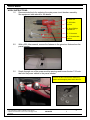
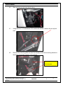
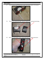
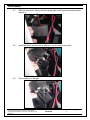
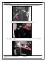
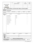
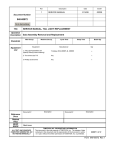
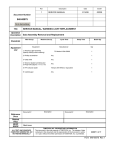
Rev
1
Description
SERVICE MANUAL
Date
ECO#
2/14/08
00239
Document Number:
040-00076
Form Instructions
Title
Operation
Description
Standards
Equipment
List
SERVICE MANUAL, MAIN POWER CIRCUIT BREAKER REPLACEMENT
Sub Assembly
Man Occup.
Machine Occup.
Equipment
Cycle Time
Setup Time
Manufacturer
Batch Qty
Qty
1- Main Power Circuit Breaker
T3 Motion
1
2- 5/32 inch Allen wrench
Any
1
3- Small Phillips screwdriver
Any
1
4- Heat gun
Any
1
5- 7/16 inch wrench
Any
1
6- 7/16 inch socket with ratchet
Any
1
7- Knife or razor blade
Any
1
Document #
Description
Description
Document #
Reference
Docs
Related
Files
RESP
ENGR
Mark Jones
ALL TEXT AND GRAPHICS
COMPUTER GENERATED, DO
NOT REVISE MANUALLY
T3MOTION, INC. PROPRIETARY INFORMATION
This document is the sole property of T3MOTION, Inc. The release of data
contained in this document and the reproduction of this document in whole
or in part, without the written permission of T3MOTION, Inc. is prohibited.
SHEET 1 of 9
Form 040-00076 Rev.1
SERVICE MANUAL
Item#
Part #
Description
Qty
1
100-00005
Circuit Breaker
1
T3MOTION PROPRIETARY INFORMATION
Use or disclosure of data contained on this sheet is
subject to the restriction on the cover or title page of this
document.
Document No
Revision
040-00076
1
Sheet
2
SERVICE MANUAL
Serious electrical
shock can occur
if precautions are
not followed.
• ALWAYS TURN OFF POWER BREAKER IN GLOVE BOX AND REMOVE POWER
MODULES BEFORE PERFORMING ANY ELECTRICAL WORK.
Power breaker in glove box
Power modules
• ALSO SET THE PARKING BRAKE PRIOR TO ANY WORK.
Parking brake
T3MOTION PROPRIETARY INFORMATION
Use or disclosure of data contained on this sheet is
subject to the restriction on the cover or title page of this
document.
Document No
Revision
040-00076
1
Sheet
3
SERVICE MANUAL
WORK INSTRUCTIONS:
1.0
Recommended tools for replacing the main power circuit breaker assembly.
See equipment table above for the details.
4- Heat Gun
2- 5/32 Allen
wrench
3- Small Phillips
screwdriver
5- 7/16 wrench
6- 7/16 socket with
ratchet.
2.0
With a 5/32 Allen wrench, remove the fastener in the glove box that anchors the
power breaker.
3.0
Reach through one of the power module openings and loosen the two 7/16 nuts
that hold the power cables to the power breaker.
Remove the two nuts and lock washers by
hand to avoid dropping them inside the unit.
T3MOTION PROPRIETARY INFORMATION
Use or disclosure of data contained on this sheet is
subject to the restriction on the cover or title page of this
document.
Document No
Revision
040-00076
1
Sheet
4
SERVICE MANUAL
4.0
Slice and remove the heat shrink tubing.
4.1
Using both the 7/16 wrench and 7/16 socket with ratchet, remove the two nylock
nuts.
4.2
Remove the mounting plate and twist the breaker switch and mounting bracket to
the left as shown then remove. Do not force.
Mounting bracket
Mounting plate
T3MOTION PROPRIETARY INFORMATION
Use or disclosure of data contained on this sheet is
subject to the restriction on the cover or title page of this
document.
Document No
Revision
040-00076
1
Sheet
5
SERVICE MANUAL
4.3
Remove the two small Phillips head screws that hold the switch to the bracket.
5.0
These are the replacement parts; a power breaker and some heat shrink tubing.
6.0
Mount the power breaker switch to the bracket with the Phillips head screws.
T3MOTION PROPRIETARY INFORMATION
Use or disclosure of data contained on this sheet is
subject to the restriction on the cover or title page of this
document.
Document No
Revision
040-00076
1
Sheet
6
SERVICE MANUAL
6.1
Slide the heat shrink tubing onto the upright part of the frame the switch bracket
mounts to.
6.2
Install the switch and bracket by putting it over the bolts at an angle.
6.3
Then rotating it to the right.
T3MOTION PROPRIETARY INFORMATION
Use or disclosure of data contained on this sheet is
subject to the restriction on the cover or title page of this
document.
Document No
Revision
040-00076
1
Sheet
7
SERVICE MANUAL
6.4
And lining it up. Then slide the switch and bracket up into place in the glove
box switch opening.
6.5
Thread the 5/32 Allen fastener into the bracket and snug it down. Make sure the
switch is aligned and does not bind.
6.6
Now install the mounting plate and thread the two nylock nuts onto the two bolts.
T3MOTION PROPRIETARY INFORMATION
Use or disclosure of data contained on this sheet is
subject to the restriction on the cover or title page of this
document.
Document No
Revision
040-00076
1
Sheet
8
SERVICE MANUAL
6.7
And tighten them with both of the 7/16 wrenches you used to remove them.
7.1
Reattach the power cables with the 7/16 nuts and lock washers.
8.0
Slide heat shrink tubing up and over the mounting plate and nuts and using the
heat gun, shrink it.
T3MOTION PROPRIETARY INFORMATION
Use or disclosure of data contained on this sheet is
subject to the restriction on the cover or title page of this
document.
Document No
Revision
040-00076
1
Sheet
9