1
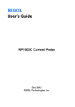
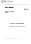
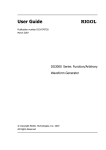
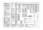
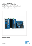
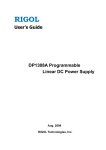
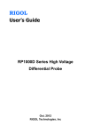
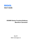
RIGOL User’s Guide RP1002C Current Probe Mar. 2013 RIGOL Technologies, Inc RIGOL Guaranty and Declaration Copyright © 2012 RIGOL Technologies, Inc. All Rights Reserved. Trademark Information RIGOL is a registered trademark of RIGOL Technologies, Inc. Publication Number UGE17102-1110 Notices RIGOL products are protected by patent law in and outside of P.R.C. RIGOL reserves the right to modify or change parts of or all the specifications and pricing policies at company’s sole decision. Information in this publication replaces all previously corresponding material. RIGOL shall not be liable for losses caused by either incidental or consequential in connection with the furnishing, use or performance of this manual as well as any information contained. Any part of this document is forbidden to be copied or photocopied or rearranged without prior written approval of RIGOL. Product Certification RIGOL guarantees this product conforms to the national and industrial standards in China as well as the ISO9001:2008 standard and the ISO14001:2004 standard. Other international standard conformance certification is in progress. Contact Us If you have any problem or requirement when using our products, please contact RIGOL Technologies, Inc. or your local distributors, or visit: www.rigol.com. RP1002C User’s Guide I RIGOL General Safety Summary Please review the following safety precautions carefully before putting the instrument into operation so as to avoid any personal injuries or damages to the instrument and any product connected to it. To prevent potential hazards, please use the instrument only specified by this manual. Ground The Instrument. The instrument is grounded through the Protective Earth lead of the power cord. To avoid electric shock, it is essential to connect the earth terminal of power cord to the Protective Earth terminal before any inputs or outputs. Observe All Terminal Ratings. To avoid fire or shock hazard, observe all ratings and markers on the instrument and check your manual for more information about ratings before connecting. Replace Fuse Properly Make sure that no overvoltage (such as voltage caused by thunderbolt) this product. Otherwise, the operator might be exposed to electric shock. Do Not Operate Without Covers. Do not operate the instrument with covers or panels removed. Avoid Circuit or Wire Exposure. Do not touch exposed junctions and components when the unit is powered. II RP1002C User’s Guide RIGOL Do Not Operate With Suspected Failures. If you suspect damage occurs to the instrument, have it inspected by qualified service personnel before further operations. Any maintenance, adjustment or replacement especially to circuits or accessories must be performed by RIGOL authorized personnel. Keep Well Ventilation. Inadequate ventilation may cause increasing of temperature or damages to the device. So please keep well ventilated and inspect the intake and fan regularly. Do Not Operate in Wet Conditions. In order to avoid short circuiting to the interior of the device or electric shock, please do not operate in a humid environment. Do Not Operate in an Explosive Atmosphere. In order to avoid damages to the device or personal injuries, it is important to operate the device away from an explosive atmosphere. Keep Product Surfaces Clean and Dry. To avoid the influence of dust and/or moisture in air, please keep the surface of device clean and dry. Electrostatic Prevention. Operate in an electrostatic discharge protective area environment to avoid damages induced by static discharges. Always ground both the internal and external conductors of the cable to release static before connecting. RP1002C User’s Guide III RIGOL Safety Terms and Symbols Terms in this Manual. These terms may appear in this manual: WARNING Warning statements indicate the conditions or practices that could result in injury or loss of life. CAUTION Caution statements indicate the conditions or practices that could result in damage to this product or other property. Terms on the Product. These terms may appear on the Product: DANGER WARNING CAUTION indicates an injury or hazard may immediately happen. indicates an injury or hazard may be accessible potentially. indicates a potential damage to the instrument or other property might occur. Symbols on the Product. These symbols may appear on the product: Double Insulation IV Safety Warning Protective Earth Terminal Chassis Ground Test Ground RP1002C User’s Guide RIGOL Contents Guaranty and Declaration ................................................... I General Safety Summary ................................................... II Safety Terms and Symbols ............................................... IV RP1002C Overview ............................................................. 1 Basic Operation .................................................................. 1 Connection between the Current Probe and Oscilloscope ....... 1 Connection between the Current Probe and Digital Meter ...... 4 Maintenance ....................................................................... 5 Battery .............................................................................. 5 To Install the Battery .......................................................... 6 AC Power Adapter .............................................................. 6 Cleaning ............................................................................ 7 Preparation for shipment .................................................... 7 Specifications ..................................................................... 8 Electrical Characteristics ..................................................... 8 Voltage and Current Ratings ................................................ 9 Physical Characteristics ....................................................... 9 Environmental Characteristics ............................................ 10 Certifications and Compliances .......................................... 10 Accessories ....................................................................... 12 Appendix ........................................................................... 13 Appendix 1 Gain versus Frequency at 1 A Peak (Typical) ..... 13 Appendix 2 Maximum Current versus Frequency ................. 14 Appendix 3 DC Signal Linearity in 50mV/A Range (Typical) .. 14 Appendix 4 Phase versus Frequency at 1 A Peak (Typical) ... 15 RP1002C User’s Guide V RIGOL RP1002C Overview The RP1002C current probe enables a general purpose oscilloscope to display AC and DC current signals up to 100 A Peak (70 A RMS). The RP1002C current probe can also make AC and DC measurements with a multimeter by using the BNC-to-banana plug adapter. Maximum Conductor Size: 11mm Test Clamp Test Clamp Button BNC Interface Power Supply Indicator Overload Indicator Zero Adjustment Knob Range Switch AC Adapter Input Figure 1 RP1002C Current Probe RP1002C User’s Guide 1 RIGOL Control/Indicator Description Current flow symbol: The arrow shows the positive direction of current flow . Zero adjustment: After connecting to power and fixing the current probe to a fixed position, rotate the knob to adjust the probe output tothe proper DC offset. It may also be used to offset a DC signal component. Zeroing is not needed for AC measurements unless your instrument cannot isolate a DC component (if present). Range switch: Slide the switch from OFF to either the 50 mV/A or 500mV/A range. When 50 mV/A or 500mV/A is selected, the probe is turned on, and the green battery indicator (ON) lights. Power Supply indicator: The green power supply indicator lights when the probe is turned on. For more information, please refer to To Install the Battery. Overload indicator: The red overload indicator lights and flicks continuously if the measured signal is greater than the maximum range of the selected range capacity. 2 RP1002C User’s Guide RIGOL Basic Operation Before using the current probe, the battery or specified AC power adapter must be installed. For the battery installation instructions, refer to To Install the Battery. CAUTION Do not clamp the probe onto circuits with voltages greater than 600 VAC. Otherwise, personal injury or damage to the probe may result. CAUTION Always connect the RP1002C current probe output to the instrument before clamping onto the circuit under test. Connection between the Current Probe and Oscilloscope 1 Set the coupling mode of the oscilloscope to DC and connect the BNC interface of the RP1002C current probe to the oscilloscope input via dual-BNC coaxial cable. 2 Move the Range switch to the 50 mV/A or 500 mV/A position to turn on the RP1002C current probe. At this point, the green battery indicator lights. 3 Use the zero adjustment knob to adjust the probe to the proper DC offset. RP1002C User’s Guide 1 RIGOL Note: when measuring DC signals, accurate DC value is possible only when the current probe is fixed at a certain position, otherwise, the change of the position of the probe will cause the DC drift. When measuring AC signals, users can move the current probe. 4 Before connecting the current probe to circuit, open the test clamp and clamp it onto the conductor as shown in the figure below. Figure 2 Connection between the Test Clamp and Conductor 2 RP1002C User’s Guide RIGOL 5 Adjust the probe channel and oscilloscope as necessary to get a clear and stable view of the signal. At this point, you can see both the current components of AC and DC. Set the coupling mode of the oscilloscope to AC to see the current components of AC. The operation method of the current components of AC is the ratio of the voltage amplitude measured through the oscilloscope and the switch range currently selected of the current probe (50 mV/A or 500 mV/A). Note: The current drawn by different devices look much different than that of others. While the RMS current can only be used in low frequency current, the momentary peaks may be quite high. The figure on the next page shows the difference between the line current drawn by a resistive load and a motor controller. Figure 3 Typical Current Waveforms RP1002C User’s Guide 3 RIGOL Connection between the Current Probe and Digital Meter Connect the BNC connector of the RP1002C current probe and the input terminal of the digital meter using the BNC-to-banana plug adapter provided with the accessories. To measure only AC current, select the AC volts of the meter. To measure DC current, select the DC volts of the meter, and adjust the probe output to the proper DC offset. When connecting the current under test, please note the current convention arrow on the test clamp to get the proper polarity reading. Note: To increase the measurement sensitivity of the RP1002C current probe, loop additional turns of the wire under test through the test clamp. The sensitivity of the RP1002C current probe is multiplied times the number of loops in the test clamp, for example, 50 mV/A X 4 turns = 200 mV/A. 4 RP1002C User’s Guide RIGOL Maintenance Battery 1 The RP1002C current probe uses a single square 9 V battery. This instrument is a high power product. Please use the specified alkaline battery. 2 As the battery in the RP1002C current probe is drained, significant measurement errors may occur. The green battery indicator will continue to light until a low battery voltage of 6.5 V is reached. Battery RP1002C User’s Guide 5 RIGOL To Install the Battery 1 Remove the test clamp from the circuit. 2 Remove the three screws on the rear cover and take off the rear cover. You can see the location of the battery and remove the battery. 3 While observing polarity, install the new alkaline battery at the corresponding location. 4 Install the rear cover. AC Power Adapter 1 The specified AC power adapter can be used to avoid measurement error due to poor battery durability. 2 When using an AC power adapter for an extended time, you are recommended to remove the battery. This is because heating will result in battery leakage, and battery electrolyte will rust the circuit board, thus creating major damage. Furthermore, as batteries are high pollution products, you are recommended to avoid using them as far as possible. 6 RP1002C User’s Guide RIGOL Cleaning To clean the probe exterior, use a soft cloth dampened in a solution of mild detergent and water. To clean the core, open the test clamp and clean the exposed core surfaces with a cotton swap dampened with isopropyl alcohol (isopropanol). Lubricate the clamp mating surfaces with light oil. Note: Do not clean with solvents or abrasives. Do not immerse the probe. Preparation for shipment A special box is provided to be used for this product, convenient for storage and shipment. Please do not discard it. If the original packaging is unfit for use or not available, use the following packaging guidelines. 1 Use a sturdy shipping carton having inside dimensions at least one inch greater than the probe dimensions. 2 Put the probe into a plastic bag or wrap to protect it from dampness. 3 Place the probe into the box and stabilize it with light packaging material. 4 Seal the carton with shipping tape. RP1002C User’s Guide 7 RIGOL Specifications These characteristics apply to an adjusted RP1002C current probe installed on an oscilloscope of any brand. The oscilloscope must be warmed up for at least 20 minutes and be in an environment with the temperature at 10℃-30℃ and the humidity at 0-80%. Electrical Characteristics Current Range DC Accuracy, typical Gain versus frequency, typical Max. Working Current Max. Working Voltage Max. Floating Voltage Frequency Range Battery Type and Life, typical DC Signal Linearity, typical Phase versus frequency, typical 8 50mV/A, 500mV/A 500mV/A: ±3% ±20mA (20mA to 14A peak range) 50mV/A: ±4% ±200mA (200mA to 100A peak range) 50mV/A: ±15% maximum (100A peak to 140A peak range) See Appendix 1 Gain versus Frequency at 1 A Peak (Typical) See Voltage and Current Ratings See Voltage and Current Ratings See Voltage and Current Ratings DC to 1MHz (-3dB) 9V NEDA 1604A, IEC 6LR61 8 hours (1 each) See Appendix 3 DC Signal Linearity in 50mV/A Range (Typical) See Appendix 4 Phase versus Frequency at 1 A Peak (Typical) RP1002C User’s Guide RIGOL Voltage and Current Ratings Parameter DC Max. Working Current (A) 50mV/A Range 500mV/A Range Max. Working Voltage (V) Max. Floating Voltage (V) 70[1] 7 600 600 [1] 7 600 600 DC+AC Peak 70 AC Peak 70 7 600 600 AC Peak-peak 140 14 1200 ---- RMS III CAT 50 5 600 600 RMS CAT II 50 5 600 600 RMS CAT I 50 5 600 600 : For frequency derating, please refer to Appendix 2 [1] Note Maximum Current versus Frequency. Physical Characteristics Dimensions Max. Conductor under test Size Dual-BNC Coaxial Cable Length Weight RP1002C User’s Guide 262mm x 81mm x 36mm 10.3mm 100cm 310g (battery excluded) 9 RIGOL Environmental Characteristics Working Temperature Storage Temperature Humidity Pollution Degree 0℃ to +50℃ -20℃ to +80℃ 0℃ to +40℃, 95% humidity +40℃ to +50℃, 45% humidity 2 Certifications and Compliances EC Declaration of Conformity – Low Voltage Additional Compliance 10 Low Voltage Directive 73/23/EEC, as amended by 93/68/EEC Low Voltage Directive 73/23/EEC, as amended by 93/68/EEC EN 61010-1/A2:1995: Safety requirements for electrical equipment for measurement, control and laboratory use - Part 1: General requirements. EN 61010-2-032:1995: Safety requirements for electrical equipment for measurement, control and laboratory use - Part 2-032: Particular requirements for hand-held current clamps for electrical measurement and test. IEC61010-1/A2:1995: Safety requirements for electrical equipment for measurement, control and laboratory use - Part 1: General requirements. IEC61010-2-032:1994: Safety requirements for electrical equipment for measurement, control, and laboratory use - Part 2-032: Particular requirements for hand-held current clamps for electrical measurement and test. RP1002C User’s Guide RIGOL Installation (Overvoltage) Category Pollution Degree RP1002C User’s Guide CAT III: Equipment in a fixed industrial location (usually permanently connected) CAT II: Equipment at this level includes appliances, portable tools, and similar products. Equipment is usually cord-connected. CAT I: Secondary (signal level) or battery operated circuits of electronic equipment. A measure of the contaminates that could occur in the environment around and within a product. Products should be used only in the environment for which they are rated. Pollution Degree 1: No pollution or only dry, nonconductive pollution occurs. Products in this category are generally encapsulated, hermetically sealed, or located in clean rooms. Pollution Degree 2: Normally only dry, nonconductive pollution occurs. Occasionally a temporary conductivity that is caused by condensation must be expected. This location is a typical office/home environment. Temporary condensation occurs only when the product is out of service. 11 RIGOL Accessories RP1002C AC Power Adapter Dual-BNC Coaxial Cable BNC-to-banana Plug Adapter 1 2 3 4 12 An Chinese and English User’s Guide A dual-BNC coaxial cable A BNC-to-banana plug adapter An AC power adapter that accords with the standard of the destination country. RP1002C User’s Guide RIGOL Appendix Appendix 1 Gain versus Frequency at 1 A Peak (Typical) RP1002C User’s Guide 13 RIGOL Appendix 2 Maximum Current versus Frequency Appendix 3 DC Signal Linearity in 50mV/A Range (Typical) 14 RP1002C User’s Guide RIGOL Appendix 4 Phase versus Frequency at 1 A Peak (Typical) RP1002C User’s Guide 15