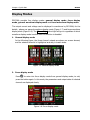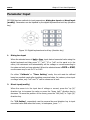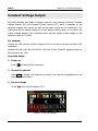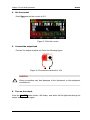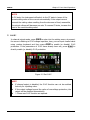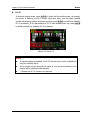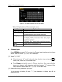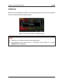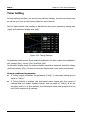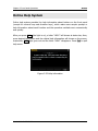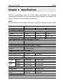
1
RIGOL User’s Guide DP1308A Programmable Linear DC Power Supply May 2009 RIGOL Technologies, Inc. RIGOL Copyright © 2009 RIGOL Technologies, Inc. All Rights Reserved. Trademark Information RIGOL is registered trademark of RIGOL Technologies, Inc. Notices RIGOL products are protected by patent law in and outside of P.R.C.. RIGOL Technologies, Inc. reserves the right to modify or change parts of or all the specifications and pricing policies at company’s sole decision. Information in this publication replaces all previously corresponding material. RIGOL shall not be liable for losses caused by either incidental or consequential in connection with the furnishing, use or performance of this manual as well as any information contained. Any part of this document is forbidden to copy or photocopy or rearrange without prior written approval of RIGOL. Product Certification RIGOL guarantees this product conforms to the standards of national and industrial. Meanwhile, the related standards conform to other ISO will get further. At present, DP1308A has passed CE, cTUVus and LXI certification. User’s Guide for DP1308A I RIGOL Safety Notices Review the following safety precautions carefully before operating the instrument to avoid any personal injuries or damages to the instrument and any product connected to it. To prevent potential hazards, do use the instrument specified by this user’s guide only. Use Proper Power Cord. Only the power cord designed for the instrument and authorized by local country could be used. Ground the Instrument. The instrument is grounded through the grounding conductor of the power cord. To avoid electric shock, the instrument grounding conductor(s) must be grounded properly before connecting the input or output terminals. Connect Output Wire Correctly. Please connect the output wire in strict accordance with operation methods in this guide. Observe all Terminal Ratings. To avoid fire or shock hazard, observe all ratings and marks on the instrument. Consult your manual for more information about ratings before connecting. Do Not Operate Without Covers. Do not operate the instrument with II covers or panels removed. Use Proper Fuse. Please use the fuse with specified voltage and current rating. Avoid Circuit or Wire Exposure. Do not touch exposed connections and components when power-on. Do not Operate with Suspected Failures. If suspected damage occurs to the instrument, have it inspected by qualified service personnel before further operations. Keep Well Ventilation. Inadequately ventilated will cause the temperature rises or damages to the device. Please keep well ventilation and inspect the intake and fan regularly. Do not Operate in Wet/Damp Conditions. In order to avoid short circuit to the interior of the device or electric shock, please do not operate in a humid environment. Do not Operate in an Explosive atmosphere. In order to avoid damages to the device or personal injury, please operate far away from an explosive atmosphere. User’s Guide for DP1308A RIGOL Keep Product Surfaces Clean and Dry. In order to prevent the performance of the device from influencing by dust or water in air, please keep the surface of device clean and dry. User’s Guide for DP1308A Handling Safety Please handle with care during transporting to avoid damages to buttons, and knobs or interfaces as well as other parts on the panel resulting from the falling from your hand. III RIGOL Safety Terms and Symbols Terms in this Guide. These terms may appear in this manual: ! WARNING Warning statements indicate the conditions or practices that could result in injury or loss of life. ! CAUTION Caution statements indicate the conditions or practices that could result in damage to this product or other property. Terms on the Product. These terms may appear on the product: DANGER indicates an injury or hazard that may immediately happen. WARNING indicates a potential injury or hazard that may happen. CAUTION indicates that a potential damage to the instrument or other property might occur. Symbols on the Product. These symbols may appear on the product: ! Hazardous Voltage IV Refer to Instructions Protective Earth Terminal Chassis Ground Test Ground User’s Guide for DP1308A RIGOL DP1308A Overview DP1308A programmable linear DC power supply is designed with high performance and 80W triple-output. It has clear user interface, excellent specifications and multiple standard interfaces, which can meet diversified testing demands. Main Features: 4.3 inch, 16M true color TFT LCD; Individual and controllable triple-channel enables to output power up to 80W in total; Low ripples noise, the output noise and ripples<350μVrms/2mVpp; Excellent load regulation rate and linear regulation rate: <0.01%+2mV (voltage), <0.01%+250μA (current); To implement effective protection for loads through setting up the corresponding parameters based on overvoltage/overcurrent protection function; Two-level over-temperature protection; Store and recall system parameters; Timing output; Waveform display: enable to display voltage/current waveform in real time and make the state of instrument understand fully at one glance coordinating with digital voltage, current and power value; Standard interfaces: USB Device, USB Host, LAN and GPIB; Support U disk store; Support remote control via Web; Support remote control via commands; Conform to LXI-C class instrument standard; One button help function; Support Chinese & English interface, input method. User’s Guide for DP1308A V RIGOL Structure of This Document Chapter 1 Quick Start This chapter introduces you the panels and display interface of DP1308A as well as some considerations when first use. Chapter 2 Front Panel Operations This chapter gives detailed information on function and operating methods about each button of the front panel. Chapter 3 Troubleshooting This chapter offers some methods to help you solve the problems during operations. Chapter 4 Specifications This chapter lists the specifications of DP1308A power supply. Chapter 5 Appendix Information about accessories, warranties, services and supports and the like. Hint: For the newest edition of this manual please go to http://www.rigolna.com/download_manual.aspx to download. Conventions about how to denote the buttons and menu softkeys from front panel in this document: Buttons: button characters + textbox, for example: +6V denotes the selection button of + 6V channel. Menu softkeys: Menu character+ character shading, for example: Volt denotes the voltage option in Channel settings. VI User’s Guide for DP1308A RIGOL Contents Safety Notices ...................................................................................... II DP1308A Overview ....................................................................................... V Chapter 1 Quick Start ............................................................................ 1-1 General Inspection .................................................................................... 1-2 Front/Rear Panels and User Interface.......................................................... 1-3 Front Panel......................................................................................... 1-3 Rear Panel.......................................................................................... 1-5 User Interface .................................................................................... 1-6 First Use DP1308A ..................................................................................... 1-7 Power Requirement............................................................................. 1-7 Power-On Inspection........................................................................... 1-7 Output Inspection ............................................................................... 1-8 Display Modes ......................................................................................... 1-11 Chapter 2 Front Panel Operations ......................................................... 2-1 Parameter Input ........................................................................................ 2-2 Constant Voltage Output ............................................................................ 2-4 Constant Current Output ............................................................................ 2-8 Timing Output ......................................................................................... 2-12 Multiplexed Output .................................................................................. 2-14 Tracking Output ...................................................................................... 2-16 Save and Recall ....................................................................................... 2-18 Set up the Utility ..................................................................................... 2-21 I/O Setting ....................................................................................... 2-22 System Setting ................................................................................. 2-24 Calibrate .......................................................................................... 2-27 Timer Setting ................................................................................... 2-28 Online Help System ................................................................................. 2-29 Key Lock ................................................................................................. 2-30 Chapter 3 Troubleshooting .................................................................... 3-1 Chapter 4 Specifications ........................................................................ 4-1 Chapter 5 Appendix ............................................................................... 5-1 Appendix A: DP1308A Accessories .............................................................. 5-1 Appendix B: Warranty ................................................................................ 5-2 User’s Guide for DP1308A VII RIGOL Appendix C: General Care and Cleaning ...................................................... 5-3 Appendix D: Contact RIGOL ....................................................................... 5-4 Index ........................................................................................................... 1 VIII User’s Guide for DP1308A Chapter 1 Quick Start RIGOL Chapter 1 Quick Start This chapter introduces you the panels and display interface of DP1308A as well as some considerations when first use. From this part, you can learn how to use this instrument quickly and correctly. Following topics are mainly throughout this chapter: General Inspection Front/Rear Panels and User Interface Front Panel Rear Panel User Interface First Use DP1308A Power Requirement Power-On Inspection Output Inspection Display Modes User’s Guide for DP1308A 1-1 RIGOL Chapter 1 Quick Start General Inspection Please inspect your new DP1308A programmable linear DC power supply according to the following steps: 1. Inspect the shipping container for damage. Keep the damaged shipping container or cushioning material until the contents of the shipment have been checked for completeness and the instrument has been checked mechanically and electrically. If the shipping container is damaged, or the protective material shows signs of stress, notify the carrier as well as your RIGOL sales representative. Keep the shipping materials for the carrier’s inspection. 2. Inspect the instrument. In case of any damage, or defect, or failure, notify the RIGOL sales representative. RIGOL offices will arrange reparation or replacement at RIGOL’s option without waiting for claim settlement. 3. Check the accessories. Accessories supplied with the instrument are listed in “Appendix A: DP1308A Accessories” at of this guide. If the contents are incomplete or damaged, please notify the RIGOL sales representative. 1-2 User’s Guide for DP1308A Chapter 1 Quick Start RIGOL Front/Rear Panels and User Interface Front Panel ① ② Programmable DC Power Supply V A mA mV ③ ④ ⑤ ⑥ ⑦ ⑧ ⑨ Figure 1-1 Front panel overview ① LCD Display user interface ② Parameters area ③ Power button Turn on (or off) the instrument ④ USB Host port Connect with external USB device as a “main equipment” ⑤ Menu softkey With different functions in different menus. ⑥ Display modes switching button Switch display modes between General and Focus ⑦ Channel button Switch channels, enable/disable channel output ⑧ Output terminal Channel output connector ⑨ Advanced function input setting User’s Guide for DP1308A Include digital keyboard, unit key (direction key) and enter key Wave Disp: Set up whether to display the signal 1-3 Chapter 1 Quick Start RIGOL area 1. through waveform Store/Recall: Store and recall the settings of instrument and files Timer: Enable timing output Utility: Set up system configuration Track: Enable track function Help: System online help Button Indicator The indicator lights when press the button to start-up the instrument. On/Off The corresponding button light will go on if turn on a channel. Wave Disp The button light will go on if enable waveform display. Timer The button light will go on if enable timing output function. ·1 Track The button light will go on if enable track function. Store/Recall The button light will go on if enter into store/recall menu. Utility The button light will go on if enter into system settings. Help The button light will go on if enter into online help. 2. Rear panel connector ① ② ③ ④ ① USB Host: Connect as a “main equipment” with an external USB device such as U disc. ② Output terminals of +6V channel ③ This terminal is connected with the chassis and ground wire when power on, which could act as an additional ground terminal for the devices connected to. ④* Output terminals of ± 25V channels NOTE*: COM is a public port. 1-4 User’s Guide for DP1308A Chapter 1 Quick Start RIGOL Rear Panel ③ ④ 0 11 5 23 0 ② 10 ① 220 GPIB LXI Class C Non Auto-MDIX FUSE: T2.5A 250V ⑤ ⑥ T2A 100V +/-10% 115V +/-10% LINE 220V +/-10% 230V +/-10% 40 ⑦ HAZARDOUS VOLTAGE INSIDE, DO NOT REMOVE THE COVER UNLESS BY SPECIFIED PERSONNEL. WARNING: MAINTAIN GROUND TO AVOID ELECTRIC SHOCK RIGOL Technologies, Inc. MADE IN CHINA ⑧ Figure 1-2 Rear panel overview ① GPIB Port Conform to IEEE 488.2 protocol ② ③ Fan Air outlet of the fan Supply Hub AC input interface ④ Power Voltage Selector Select the proper level according to the input power supply ⑤ LAN Port Access LAN via RJ45 port ⑥ USB Port Connect as a “slave unit” with an external USB device. ⑦ Fuse Offer two types of specifications: 250V, T3A and 250V, T2A ⑧ Power Switch Power-on/off the power Device User’s Guide for DP1308A 1-5 Chapter 1 Quick Start RIGOL User Interface ① ② ③ ④ ⑤ ⑥ ⑦ ⑧ ⑨ ⑩ ⑪ ⑫ ⑬ ⑭ ⑮ ⑯ ⑰ ⑱ ⑲ ⑳ 21 22 24 23 Figure 1-3 User interface of DP1308A ① Channel output state ⑬ Output voltage ② Channel mark ⑭ Output current ③ Selected channel* ⑮ Output power ④ Constant voltage output ⑯ O.V.P input box ⑤ LAN connecting ⑰ O.C.P input box ⑥ Keylock ⑱ Operation menu ⑦ Self-test failed ⑲ Timing output mark ⑧ O.T.P mark ⑳ Time for timing output ⑨ Remote control connecting 21 Voltage input box ⑩ U disk detected 22 Current input box ⑪ Help system mark 23 Track mark ⑫ The beeper is enabled 24 O.V.P/O.C.P state NOTE*: The channel is highlighted on the screen (in breath state). 1-6 User’s Guide for DP1308A Chapter 1 Quick Start RIGOL First Use DP1308A Before operating, please do perform necessary inspections to ensure the instrument is in a good position to work normally. Power Requirement Four types of AC power within 50Hz-60Hz of frequency are provided by DP1308A: 100V, 115V, 220V, 230V. You can choose an appropriate input power as required through switching the “Power Voltage Selector” on the rear panel. ! WARNING Before switching the “Power Voltage Selector”, make sure that the power supply has been cut off and the instrument has installed specified fuse. Power-On Inspection Please use the power cord listed in accessories to connect the instrument with AC supply, and then perform the following instructions: 1. Turn on the instrument Turn on the power switch on the rear panel. (At present, the instrument has connected to AC supply.) ! 2. WARNING To avoid electric shock, make sure that the instrument has properly grounded. Turn on the power button Press down the power button on the front panel to enable the self-test. If pass test, the user interface will appear on screen, or else a clue “System power-on self-test has a mistake, view the error or not?” will pop up, press OK to get more information about fail, or press Cancel to exit clue. User’s Guide for DP1308A 1-7 Chapter 1 Quick Start RIGOL Output Inspection In virtue of this function, the instrument enables to respond to front panel correctly and output rated value. The inspections are mainly centered on the voltage output on the occasion of no loads for each channel and the current output when short circuit. 1. Channel selection and output switch Choose an appropriate output channel using selection buttons. The selected channel will be highlighted on screen. Figure 1-4 Output channel selection Turn on/off the output by pressing On/Off button under the selection button of each channel. After you enable the output of a channel, the corresponding button will light until you disable the output regardless of whether it is the current channel or not. 2. Voltage output inspection (1) When the instrument has no load: Press power button and make sure that the setting value of current in each channel is not 0; (2) Inspect “all on” and “all off” function of channels; 1-8 Press All On button, then a clue about whether to open output of all channels will appear on, if click ok, all the channel buttons light will go on that denotes they are ready to output; on the contrary, the instrument backs to the state before. Press All Off buttons to disable the output of all channels. Meanwhile, the corresponding On/Off button is black out. User’s Guide for DP1308A Chapter 1 Quick Start RIGOL (3) Inspect the voltage function of +6V channel; Press +6V button and the corresponding On/Off button, the channel will be in constant voltage output state after On/Off button light goes on, then check whether the “voltage” can be adjusted from 0 to the maximum rated value(6.3V). See the “Parameter Input” section in chapter 2. (4) Inspect the voltage function of +25V channel; Press +25V button and the corresponding On/Off button, the channel will be in constant voltage output state after On/Off button light goes on, then check whether the “voltage” can be adjusted from 0 to the maximum rated value(26.25V). (5) Inspect the voltage function of -25V channel; Press -25V button and the corresponding On/Off button, the channel will be in constant voltage output state after On/Off button light goes on, then check whether the voltage can be adjusted from 0 to the minimum rated value(-26.25V). 3. Current output inspection (1) Press the power button . (2) Press All Off button to disable the output of all channels. (3) Inspect the current function of +6V channel. Short the terminal (+) and (-) of +6V channel using an insulating output lead; Press +6V button; Set the voltage as 6V; Press the corresponding On/Off button of +6V channel; After On/Off button light goes on, check whether the “current” can be adjusted from 0 to the maximum rated value (5.25A). (4) Inspect the current function of +25V channel. Short the terminal (+) and (COM) of +25V channel using an insulating testing lead; Press +25V button; Set the voltage value as 25V; User’s Guide for DP1308A 1-9 RIGOL Chapter 1 Quick Start Press the corresponding On/Off button of +25V channel; After On/Off button light goes on, check whether the “current” can be adjusted from 0 to the maximum rated value (1.05A). (5) Inspect the current function of -25V channel. Short the terminal (-) and (COM) of -25V channel using an insulating testing lead; Press -25V button; set the voltage value as -25V; Press the corresponding On/Off button of -25V channel; After On/Off button light goes on, check whether the current can be adjusted from 0 to the maximum rated value (1.05A). - 1-10 User’s Guide for DP1308A Chapter 1 Quick Start RIGOL Display Modes DP1308A provides four display modes: general display mode, focus display mode, general waveform display mode and focus waveform display mode. The output current and voltage can be displayed in waveforms by DP1308A, for the details , please see general waveform display mode (Figure 1-7) and focus waveform display mode (Figure 1-8). The Wave Disp button light will go on regardless of which waveform display mode is active until this function is disabled. 1. General display mode In the following figure, the three channel outputs are shown on screen abreast, and the selected channel is highlighted and stay in breath state. Figure 1-5 General display mode 2. Focus display mode Press to enter into focus display mode from general display mode; to exit, press the button again. In this mode, the parameters and output state of selected channel are displayed clearly. Figure 1-6 Focus display mode User’s Guide for DP1308A 1-11 Chapter 1 Quick Start RIGOL 3. General waveform display mode Press Wave Disp button in general display mode or press in focus waveform display mode to enter into general waveform display mode. The state of Wave Disp button light varies with channel display mode. The waveforms from all three channels could be displayed simultaneously in this mode. Figure 1-7 General waveform display mode 4. Focus waveform display mode Press in general waveform display mode or press Wave Disp button in focus display mode to enter into focus waveform display mode. In this mode, the parameters and channel output state are displayed clearly. Figure 1-8 Focus waveform display mode 1-12 User’s Guide for DP1308A Chapter 2 Front Panel Operations RIGOL Chapter 2 Front Panel Operations This chapter gives detailed information on function and operating methods about each button on the front panel, among them, you will learn more about DP1308A and make primary work. Following topics are mainly throughout this chapter: Parameter Input Constant Voltage Output Constant Current Output Timing Output Multiplexed Output Tracking Output Save and Recall Set up the Utility I/O Setting System Setting Calibrate Timer Setting Online Help System Key Lock User’s Guide for DP1308A 2-1 Chapter 2 Front Panel Operations RIGOL Parameter Input DP1308A has two methods to input parameters: dialog box input and direct input (modify). Parameters can be inputted by the digital keyboard and unit key (direction key). Figure 2-1 Digital keyboard and unit key (direction key) 1. Dialog box input When the selected menu is Volt or Curr, input desired numerical value using the digital keyboard and then press “V”, “mV”, “A” or “mA” on the panel or in the menu, the instrument will automatically set the voltage or current according to the value and unit you have selected. When the selected menu is O.C.P or O.V.P, use the same way to set O.C.P or O.V.P. For either “Calibrate” or “Timer Setting” mode, the unit must be defined based on practical needs after inputting numerical value, for instance, when input a voltage value, only “mV” and “V” can be chosen as its unit. 2. Direct input(modify) When the cursor is in the input box of voltage or current, press the “up (V)” direction key to increase the value or press the “down (mV)” direction key to decrease. To move the position of the cursor, press the “left (mA)” or “right (A)” direction key. For “I/O Setting”, respectively use the numeral key and direction key to input numerical value and move the cursor; to backspace, press “←”. 2-2 User’s Guide for DP1308A Chapter 2 Front Panel Operations RIGOL NOTE A long press on up or down direction key may change the setting value of current or voltage quickly and linearly; if on left or right direction, the position of the cursor could be moved quickly. While inputting the file name, the position of the cursor can be moved quickly If press direction keys for long time. User’s Guide for DP1308A 2-3 Chapter 2 Front Panel Operations RIGOL Constant Voltage Output DP1308A provides two kinds of output mode for each channel including Constant Voltage Output (CV) and Constant Current Output (CC), which is depends on the specified voltage and current as well as the loads carried by the instrument. The instrument will not output voltage or current beyond setting value. In CV mode, the output voltage equals to the specified value and the output current equals to the specified value in CC mode. For example: Choose the +6V channel; set the voltage to 6V, the current to 5A and the load to 5Ω separately. Because 5Ω× 5A=25V>6V and 6V/5Ω=1.2A<5A, so the Constant Voltage Output of the channel is 6V, 1.2A. Operation Steps: 1. Power on Press to start-up the instrument. 2. Choose the channel Press +6V to enable +6V channel, at present, the channel is highlighted on the screen (in breath state). 3. Set the voltage Press Volt and set the voltage to 6 V. Figure 2-2 Set the voltage 2-4 User’s Guide for DP1308A Chapter 2 Front Panel Operations RIGOL 4. Set the current Press Curr and set the current to 5 A. Figure 2-3 Set the current 5. Connect the output lead Connect the output terminal of+6V as the following figure: Figure 2-4 Connect the terminal of +6V CAUTION ! Wrong connection may lead damages to the instrument or the equipment connected to. 6. Turn on the output Press the On/Off button below +6V button, and which will be lightened during the output until you press again. User’s Guide for DP1308A 2-5 Chapter 2 Front Panel Operations RIGOL NOTE In CV state, the instrument will switch to the CC state in terms of the preset setting value of the current automatically if the output current exceeds the setting value resulting from the decrease of load, meanwhile, the output voltage will decrease pro rata. To resume CV state, increase the load or the current setting value. 7. O.V.P* In channel output mode, press O.V.P to enter into the setting menu, at present, the cursor is flashing in O.V.P voltage input box, here, you can input needed value using number keyboard and then press O.V.P to enable (or disable) O.V.P protection. If the parameters of O.V.P have already been set, press O.V.P to directly enable (or disable) O.V.P protection. Figure 2-5 Set O.V.P NOTE 2-6 If channel output is disabled, the O.V.P function can not be enabled but only for inputting value. If the output voltage beyond the value of overvoltage protection, the output will be disabled automatically. *: Please use O.V.P function as required. User’s Guide for DP1308A Chapter 2 Front Panel Operations RIGOL 8. O.C.P* In channel output mode, press O.C.P to enter into the setting state, at present, the cursor is flashing in O.C.P current input box, here, you can input needed current value using number keyboard and then press O.C.P to enable (or disable) O.C.P protection. If the parameters of O.C.P have already been set, press O.C.P to directly enable (or disable) O.C.P protection. Figure 2-6 Set O.C.P NOTE If channel output is disabled, the O.C.P function can not be enabled but only for inputting value. If the output current beyond the value of over current protection, the output will be disabled automatically. *: Please use O.C.P function as required. User’s Guide for DP1308A 2-7 Chapter 2 Front Panel Operations RIGOL Constant Current Output For example: Choose the +6V channel; set the voltage to 6V, the current to 5A and the load to 1Ω separately. Because 6V/1Ω=6A>5A and 5A× 1Ω=5V<6V, so the Constant Current Output of the channel is 5A, 5V. Operation Steps: 1. Power on Press to start-up the instrument. 2. Choose the Channel Press +6V to enable +6V channel, at present, the channel is highlighted on the screen (in breath state). 3. Set the voltage Press Volt and set the voltage to 6 V. Figure 2-7 Set the voltage 4. Set the current Press Curr and set the current to 5 A. 2-8 User’s Guide for DP1308A Chapter 2 Front Panel Operations RIGOL Figure 2-8 Set the current 5. Connect the output lead Connect the output terminal of+6V as the following figure: Figure 2-9 Connect the terminal of +6V ! CAUTION Wrong connection may lead damages to the instrument or the equipment connected to. 6. Turn on the output Press the On/Off button below +6V button and which will be lightened during the output until you press again. User’s Guide for DP1308A 2-9 Chapter 2 Front Panel Operations RIGOL NOTE In CC state, the instrument will switch to the CV state in terms of the preset setting value of the voltage automatically if the output voltage exceeds the setting value resulting from the increase of load, meanwhile, the output current will decrease pro rata. To resume CC state, decrease the load or increase the voltage setting value. 7. O.V.P* In channel output mode, press O.V.P to enter into the setting state, at present, the cursor is flashing in O.V.P voltage input box, here, you can input needed value using number keyboard and then press O.V.P to enable (or disable) O.V.P protection. If the parameters of O.V.P have already been set, press O.V.P to directly enable (or disable) O.V.P protection. Figure 2-10 Set the O.V.P NOTE 2-10 If channel output is disabled, the O.V.P function can not be enabled but only for inputting value. If the output voltage beyond the value of overvoltage protection, the output will be disabled automatically. *: Please use O.V.P function as required. User’s Guide for DP1308A Chapter 2 Front Panel Operations RIGOL 8. O.C.P* In channel output mode, press O.C.P to enter into the setting state, at present, the cursor is flashing in O.C.P current input box, here, you can input needed current value using number keyboard and then press O.C.P to enable (or disable) O.C.P protection. If the parameters of O.C.P has already been set, press O.C.P to directly enable (or disable) O.C.P protection. Figure 2-11 Set O.C.P NOTE If channel output is disabled, the O.C.P function cannot be enabled but only for inputting value. If the output current beyond the value of overcurrent protection, the output will be disabled automatically. *: Please use O.C.P function as required. User’s Guide for DP1308A 2-11 Chapter 2 Front Panel Operations RIGOL Timing Output Press Timer to enable the timing output of current channel, at this moment, the button light goes on and a “Clock” icon and the corresponding timing parameters are shown on the screen. See the figure below. The instrument will start output after you turn on the current channel until finishing all timing outputs. (at the same time, the light of Timer button goes out.) If no timing parameters have been set before enabling the timer, the system will enter “Timer Setting” Interface automatically after you press Timer (the light goes on). In timing mode, if you turn off the channel under timing, the timer will stop until it is enabled again. However, the timer would be disabled once you press Timer during timing. Clock icon Specified time Figure 2-12 Timing output (in focus display mode) In focus display mode, the character “Set” on the screen denotes the current output voltage and current setting value while “Next” denotes the next output voltage and current setting value. The next output value does not displayed in normal display mode, see the figure below. Figure 2-13 Timing output (normal display mode) 2-12 User’s Guide for DP1308A Chapter 2 Front Panel Operations RIGOL To change the voltage, current or the time that has been set, press Utility to enter the “TimerSet” menu. NOTE If the timing output is enabled on a channel, of which Volt and Curr values can’t be set. Timing Output can not be used if tracking function of +25V (-25V) channel is active. User’s Guide for DP1308A 2-13 Chapter 2 Front Panel Operations RIGOL Multiplexed Output Typically, all three channels of DP1308A enable to output synchronously, and each of them could be controlled independently. Operation Steps: 1. Power on Press to start-up the instrument. 2. Choose and set channels Press the channel selection button to choose the channel required to output, then separately set the voltage and current for each of them. 3. Connect the output lead The connection method of output terminals are given as follow, you can use a cable with banana plug or a common cable to connect them with customers. +25V COM COM -25V Figure 2-14 Connect the multiplexed terminals 4. Turn on the output Press All On, and the system will prompt whether to turn on the output of all channels. If you select “ok”, the On/Off button of the corresponding channel will be light, which indicates that all channel outputs are enabled; conversely the instrument returns the state before. 5. Set O.V.P and O.C.P In output state, you can set O.V.P and O.C.P parameters for each channel if necessary. 2-14 User’s Guide for DP1308A Chapter 2 Front Panel Operations RIGOL 6. How to output 0V~50V power* DP1308A can output 0V~50V power by connecting +25V channel in series with -25V channel, see the figure below. +25V -25V Figure 2-15 Connect +25V and -25V channel in series NOTE* When +25V channel is connecting with -25V channel in series, the output voltage is the sum of the two channels’ output voltage, while the output current may be one of the two channels’ output current. User’s Guide for DP1308A 2-15 Chapter 2 Front Panel Operations RIGOL Tracking Output The ± 25V channel provides tracking output function, which denotes that the voltage of a channel can vary with the one of another channel. Select a channel such as +25V, and then press Track, at present, the button lights and a track icon tracking mode. appears at the lower left of +25V that denotes +25V is in Figure 2-16 Tracking output (before tracking) Next, change the voltage of -25V channel, and then the voltage of +25V channel changes along with it*. For example: Change the voltage of -25V channel to 2.5V, the voltage of +25V channel is also changed to 2.5V, please see the figure below. Figure 2-17 Tracking output (after tracking) Press Track again to disable track function and the light is out. 2-16 User’s Guide for DP1308A Chapter 2 Front Panel Operations RIGOL NOTE *: Track function is only available for the voltage setting value but has nothing to do with the output value. The voltage of channel under tracking varies with the value of channel to be tracked only when both channels are in CV state. Track function is forbidden when “Timing Output” of +25V (-25V) channel is active. The voltage of channel under tracking can not be set manually when track function is enabled. User’s Guide for DP1308A 2-17 Chapter 2 Front Panel Operations RIGOL Save and Recall DP1308A supports two types of document storage ways: U disc storage and local storage. Among the internal memory, 4 groups of settings could be saved or recalled and more settings are available for USB device. Press Store/Recall to enter the Save and Recall interface (the button is light). To exist, press this button again. See as figure 2-18. Figure 2-18 Save and recall interface Table 2-1 Explanations of save and recall menus Menu Explanations Browser Shift cursor between directory and file window Store Enter the Save interface Recall Recall the selected system configuration file Delete Delete the selected file Enter next page Back to previous page Update Select the desired file and update Exit Exit the save and recall interface Press Store to enter the interface below, press InType to switch the input method. 2-18 User’s Guide for DP1308A Chapter 2 Front Panel Operations RIGOL Figure 2-19 Input interface of the file name Table 2-2 Explanations of file name input menu Menu Explanations Input Method Chinese or English Focus Cursor Shift cursor among the input box of file name, virtual keyboard and Chinese show box ABC(abc) Switch capital and lower case. If display “ABC”, lowercase letter and pinyin could be inputted. If display “abc”, capital letter could be inputted. Save Save system configuration file Back to save and recall interface 1. Chinese Input Press InType and select “Ch” to enter the Chinese input interface as the figure above. Take file name “北京普源” as an example: (1) Input “北京普源” Select character “b” in soft keyboard using direction keys and press OK to input, then, input “bei” in the same way. Press Focus and switch cursor to Chinese input box, then press direction keys up or down to shift characters until the character “北” appears. After that, input the whole name file “北京普源” in the same way. (2) Delete the wrong characters you input In the process of editing, if press “←”, the characters in display box will be deleted at first. User’s Guide for DP1308A 2-19 Chapter 2 Front Panel Operations RIGOL (3) Save the file Press Save to save the file as the specified name and finish editing. 2. English Input Press InType and select “En” to enter the English input interface as the figure below. Take file name “newfile” as an example: Figure 2-20 English Input (1) Input “newfile” Select character “n” in soft keyboard using direction keys and press OK to input, then, input “newfile” in the same way. (2) Delete the wrong letters you input Shift the focus cursor to the input box, then select the letter to be deleted using left/right direction key and press “←” to delete. (3) Save the file Press Save to save the file as the specified name and finish editing. NOTE The length of Chinese file name must be less than 6 characters and the English name must be less than 12 letters (including number). 2-20 User’s Guide for DP1308A Chapter 2 Front Panel Operations RIGOL Set up the Utility Press Utility (the light is on) to enter the utility interface as the figure below. Figure 2-21 Utility Setting interface Table 2-3 Explanations of utility setting menu Menu I/O Explanation Set the LAN parameters and GPIB address and view the ID of USB device Set system parameters Calibrate Enter the calibration interface TimerSet Set the timing parameters for each channel Exit Exist system menu User’s Guide for DP1308A 2-21 Chapter 2 Front Panel Operations RIGOL I/O Setting DP1308A provides LAN, USB and GPIB three interfaces for communication; you can set and review the related parameters through setting interface. 1. LAN Press I/O → LAN, enter the following interface. Net Connection: Link/Unlink IP configuration mode: DHCP/ Auto IP/Manual IP MAC Address VISA Name Figure 2-22 Set the LAN General condensed summaries: If “DHCP” is selected, the instrument will automatically assign “IP Address”, “Mask”, “Gateway” and “DNS Server”. If “Auto IP” is selected, the instrument will automatically assign “IP Address” and “Mask”. If “Manual IP” is selected, “IP Address”, “Mask”, “Gateway” and “DNS Server” has to be set manually. If both “DHCP”, “Auto IP” and “Manual IP” are selected, the priority is from high to low: “DHCP”, “Auto IP” and “Manual IP”. Default settings: In the second page of I/O menu, press Default → OK to recall the default setting of LAN. See the following figure. 2-22 User’s Guide for DP1308A Chapter 2 Front Panel Operations RIGOL Figure 2-23 Recall the default setting of LAN 2. USB Press I/O → USB, enter the following interface. This option shows the ID information about USB device with setup-free. Figure 2-24 USB ID information 3. GPIB Press I/O → GPIB, enter the following interface. The range of GPIB address is 1~30. See the figure below, directly input the desired address by number keyboard and then press OK to save. Press “←” or the left direction key to delete the number before the cursor. Figure 2-25 Set the GPIB address User’s Guide for DP1308A 2-23 Chapter 2 Front Panel Operations RIGOL System Setting Press to enter the system setting menu, which including language, power-on and brightness, information. over-temperature protection, beeper, self-test and system Figure 2-26 System settings 1. Language Setting Press Language to enter the setting interface of system language. The optional languages are “Chinese” and “English”. 2. PowerOn Setting Press PowerOn to enter the setting interface. The optional settings are “Default” and “Last”. “Default”: Factory settings will be recalled when reset the instrument. “Last”: Settings before last power-off will be recalled when reset the instrument. 3. Brightness Setting Press Bright to enter the brightness setting interface. The brightness of display screen could be regulated by pressing “+”/ “-” key (in menu) or left/right direction key. Figure 2-27 Brightness setting 2-24 User’s Guide for DP1308A Chapter 2 Front Panel Operations 4. RIGOL Over-temperature Protection Setting Press O.T.P to enter the over-temperature protection setting interface. The over-temperature protection includes two grades. Users can turn ON or OFF the first-grade protection. A mark will appear at the Status Bar when the protection is turned on, see as follow: Figure 2-28 Over-temperature Protection Settings The second-grade protection is a mandatory protection which is always on. 5. Beeper Setting Press Beeper to enter into setting interface. A sign would shown at Status Bar once you turn on beeper, which indicates that the instrument may buzzed once pop up a hint message or some button is pressed down. Figure 2-29 Beeper settings User’s Guide for DP1308A 2-25 Chapter 2 Front Panel Operations RIGOL 6. SelfTest Press SelfTest to enter the following interface. Users can perform self-test and view its result. If do not carry out self-test, the display is the results when power on. Figure 2-30 Self-Test menu Figure 2-31 View Self-Test Result 7. View System Information Press Sysinfo to view the Model, Serial Number, Hardware Version, Logic Version and Software Version of the instrument. Figure 2-32 System information settings 2-26 User’s Guide for DP1308A Chapter 2 Front Panel Operations RIGOL Calibrate Before enter the calibration interface, correct password must be input. The instrument has been calibrated before leaving factory. Figure 2-33 Input interface of calibration code NOTE Please do not calibrate privately without permission. For calibration help, please refer to “DP1308A Service Guide” or contact RIGOL technical support. User’s Guide for DP1308A 2-27 Chapter 2 Front Panel Operations RIGOL Timer Setting In timer setting interface, you can set user-defined voltage, current and output time as well as up to five groups timing output for each channel. See the figure below: the interface is divided into two parts: parameter setting area (right) and waveform display area (left). Figure 2-34 Timing Settings In parameter setting area, three kinds of parameters for each output are available to set: voltage (Volt), current (Curr) and time (Set). In waveform display area, the system displays waveform based on specified voltage (Volt) and current (Curr) for user to view the output state more clearly and directly. General condensed summaries: If Timing output is disabled, the parameter “Left(s)” in parameter setting area is equal to “Set(s)”. If Timing Output is enabled, the instrument starts output with first group of settings after you enable relative channel, and the value of “Left(s)” is on the decrease until to 0, at this moment, the instrument enters next group and so on until finish outputs of all settings. 2-28 User’s Guide for DP1308A Chapter 2 Front Panel Operations RIGOL Online Help System Online help system provides the help information about buttons on the front panel (except for numeric keys and direction keys), which make users acquire prompt or help information about each function and the operation methods more conveniently and quickly. After you press Help (the light is on), a letter “HELP” will shown at status bar; then, press desired help button and the related help information will shown on the screen, meanwhile, Help light goes out and the letter “HELP” disappears. Press Exit to quit help menu. Figure 2-35 Help information User’s Guide for DP1308A 2-29 Chapter 2 Front Panel Operations RIGOL Key Lock This function is widely used in product line of industry to avoid misoperation. 1. Local Mode In Local mode, press and hold “Little Key ” (number 7) in digital keyboard to lock all buttons except power button sign again. 2. ,“Little Key” and All Off, at the moment, a appears on the screen. To unlock the keyboard, press “Little Key” Remote Mode In Remote mode, all buttons are locked automatically except power button , “Little Key” and All Off. To exit remote mode, press “Little Key” again. 2-30 User’s Guide for DP1308A Chapter 3 Troubleshooting RIGOL Chapter 3 Troubleshooting 1. (1) (2) (3) After the instrument is powered on, the screen still dark (no display): Check the power cord connection. Ensure the power indicator is lighting and flickering. Pull out the power cord from instrument and ensure the voltage selector is in right scale and the fuse is suitable and intact. (4) If the problem still remains, please ask RIGOL for help. 2. Constant voltage output is abnormal: (1) Check whether the maximum power from selected channel meets load requirement. (2) If meet, please do: Verify whether the current value of this channel is appropriate, if lower, please increase it in moderation. Ensure the cord used for connecting load and power contracts well and no short circuit occurs. Check if the load goes wrong. (3) If the problem still remains, please ask RIGOL for help. 3. Constant current output is abnormal: (1) Check whether the maximum power of selected channel meets load requirement. (2) If meet, please do: Verify whether the voltage value of channel is appropriate, if lower, please increase it in moderation. Ensure the cord used for connecting load and power contracts well and no short circuit occurs. Check if the load goes wrong. (3) If the problem still remains, please ask RIGOL for help. 4. (1) (2) (3) (4) U disk can’t be identified: Check whether the U disk works normally. Ensure the U disk used now is Flash, as the hard disk can not be supported. Restart the instrument and insert U disk again. If the problem still remains, please ask RIGOL for help. User’s Guide for DP1308A 3-1 Chapter 4 Specifications RIGOL Chapter 4 Specifications DP1308A Programmable Linear DC Power Supply specification and operating characteristics are based on the instrument having been operated continuously for 30 minutes under the specified operating temperature. NOTE: All the specifications below apply to all the three channels output unless where noted. Model DP1308A Channels +6V DC output (@ 0℃~40℃) +25V -25V Voltage 0~+6V 0~+25V 0~-25V Current 0~5A 0~1A 0~1A Overvoltage Protection 0.1V~6.5V 0.1V~27V -0.1V~-27V Overcurrent Protection 0.1A~5.5A 0.1A~1.2A 0.1A~1.2A Load Regulation± (output percentage + offset) Voltage <0.01%+2mV Current <0.01%+250μA Linear Regulation± (output percentage + offset) Voltage <0.01%+2mV Current <0.01%+250μA Ripple and Noise (20 Hz~20 MHz) Normal Mode Voltage <350μVrms/2mVpp Normal Mode Current <2mArms <500μArms Common Mode Current <1.5μArms [1] Accuracy 12 Months (25℃± 5℃)± (output percentage + offset) Program ming Voltage 0.1%+5mV 0.05%+20mV Current 0.2%+10mA 0.15%+4mA Read Back Voltage 0.1%+5mV 0.05%+10mV Current 0.2%+10mA 0.15%+4mA Programming 0.5mV/0.5mA 1.5mV/0.1mA Read Back 0.5mV/0.5mA 1.5mV/0.1mA Meter 1mV/1mA 10mV/1mA Resolution Transient Response Time User’s Guide for DP1308A 4-1 Chapter 4 Specifications RIGOL Less than 50μs is spent on recovering the voltage within 15mV during the output current changes from full load to half load or half to full. Command Processing Time[2] <50ms Temperature Coefficient per ℃(output percentage + offset) Voltage Current Stability 0.01%+2mV 0.01%+3mV 0.02%+3mA 0.01%+0.5mA [3] ± (output percentage + offset) Voltage 0.03%+1mV 0.02%+2mV Current 0.1%+3mA 0.05%+1mA Voltage Programming Speed(to within 1% of total variation range) Rising Falling Full Load 11ms 50ms No Load 10ms 45ms Full Load 13ms 20ms No Load 200ms 400ms OVP/OCP Accuracy ± (output percentage + offset) 0.5%+0.5V/0.5%+0.5A Activation Time 1.5ms (OVP≥ 3V) <10ms (OVP<3V and OCP) Machine Dimension 235 mm (W) x 155 mm (H) x 384 mm (D) Weight 8.5 kg Power Supply AC Output (50Hz-60Hz) 100Vac+10%, 115Vac+10%, 220Vac+10%, 230Vac+10% Environment Full rated value output: 0℃~40℃ Working Temperature At higher temperature: the output current falls into 50% at the maximum temperature 55℃ Cooling Method Fan cooling Remarks: [1] Specifications are for one hour warm-up and at 25℃. [2] The maximum time required for regulating corresponding output when received APPLy and SOURce commands. [3] The variation of output within 8 hours after warm-up 30 minutes and both the load circuit and environment temperature are in constant conditions. 4-2 User’s Guide for DP1308A Chapter 5 Appendix RIGOL Chapter 5 Appendix Appendix A: DP1308A Accessories Standard Accessories: A power cord that fits the standard of destination country An USB data cable A CD (including User’s Guide) An User Instructions An INSTRUCTION Four fuses (two of 250V/T3A and two of 250V/T2A) NOTE: All the accessories are available by contacting your local RIGOL office. User’s Guide for DP1308A 5-1 RIGOL Chapter 5 Appendix Appendix B: Warranty RIGOL warrants that it’s products mainframe and accessories will be free from defects in materials and workmanship within the warranty period. If a product proves defective within the respective period. RIGOL guarantees the free replacement or repair of products which are approved defective. To get repair service or obtain a copy of the whole warranty statement, please contact with your nearest RIGOL sales and service office. RIGOL does not provide any other warranty items except the one being provided by this summary and the warranty statement. The warranty items include but not being subjected to the hint guarantee items related to tradable characteristic and any particular purpose. RIGOL will not take any responsibility in cases regarding to indirect, particular and ensuing damage. 5-2 User’s Guide for DP1308A Chapter 5 Appendix RIGOL Appendix C: General Care and Cleaning General Care Do not store or leave the instrument in where the instrument exposed to direct sunlight for long periods of time. Caution To avoid damages to the instrument, do not expose it to liquids which have causticity. Cleaning Clean the instrument often based on the operating conditions. To clean the exterior surface, perform the following steps: 1. Disconnect the instrument from all power sources. 2. Clean the loose dust on the outside of the instrument with a lint- free cloth (with a mild detergent and water). When clean the LCD, take care to avoid scarifying it. ! WARNING To avoid injury resulting from short circuit, make sure the instrument is completely dry before reconnecting into a power source. User’s Guide for DP1308A 5-3 Chapter 5 Appendix RIGOL Appendix D: Contact RIGOL If you have any problem or requirement during using our products, please contact RIGOL Technologies, Inc. or the local distributors. Domestic: Please call Tel: (86-10) 8070 6688 Fax: (86-10) 8070 5070 Service & Support Hotline: 800 810 0002 9:00 am –5: 00 pm from Monday to Friday Or by e-mail: [email protected] Or mail to: RIGOL Technologies, Inc. 156# CaiHe Village, ShaHe Town, ChangPing District, Beijing, China Post Code: 102206 Overseas: Contact the local RIGOL distributors or sales office. For the latest product information and service, visit our website: http://www.rigolna.com/ 5-4 User’s Guide for DP1308A RIGOL Index Brightness ................................. 2-24 Calibration ................................. 2-27 CC .............................................. 2-4 Cleaning ...................................... 5-3 Command Processing Time ........... 4-2 CV .............................................. 2-4 DC output ................................... 4-1 GPIB ......................................... 2-23 LAN .......................................... 2-22 Language .................................. 2-24 Linear Regulation ......................... 4-1 Load Regulation ........................... 4-1 Local Mode ................................ 2-30 User’s Guide for DP1308A Noise ........................................... 4-1 O.C.P........................................... 2-7 O.V.P ........................................... 2-6 Power-On .................................. 2-24 Resolution.................................... 4-1 Ripple .......................................... 4-1 Stability ....................................... 4-2 Temperature Coefficient ................ 4-2 Timing ................. 2-1, 2-2, 2-12, 2-28 Transient Response Time .............. 4-1 USB ........................................... 2-23 Voltage Programming Speed ......... 4-2 1