1
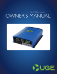
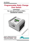
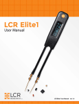
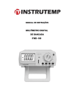
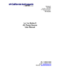
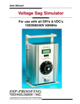
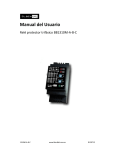
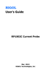
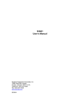
RIGOL User’s Guide RP1000D Series High Voltage Differential Probe Oct. 2012 RIGOL Technologies, Inc RIGOL Guaranty and Declaration Copyright © 2012 RIGOL Technologies, Inc. All Rights Reserved. Trademark Information RIGOL is a registered trademark of RIGOL Technologies, Inc. Publication Number UGE18100-1110 Notices RIGOL products are protected by patent law in and outside of P.R.C. RIGOL reserves the right to modify or change parts of or all the specifications and pricing policies at company’s sole decision. Information in this publication replaces all previously corresponding material. RIGOL shall not be liable for losses caused by either incidental or consequential in connection with the furnishing, use or performance of this manual as well as any information contained. Any part of this document is forbidden to be copied or photocopied or rearranged without prior written approval of RIGOL. Product Certification RIGOL guarantees this product conforms to the national and industrial standards in China as well as the ISO9001:2008 standard and the ISO14001:2004 standard. Other international standard conformance certification is in progress. Contact Us If you have any problem or requirement when using our products, please contact RIGOL Technologies, Inc. or your local distributors, or visit: www.rigol.com. RP1000D User’s Guide I RIGOL General Safety Summary Please review the following safety precautions carefully before putting the instrument into operation so as to avoid any personal injuries or damages to the instrument and any product connected to it. To prevent potential hazards, please use the instrument only specified by this manual. Ground The Instrument. The instrument is grounded through the Protective Earth lead of the power cord. To avoid electric shock, it is essential to connect the earth terminal of power cord to the Protective Earth terminal before any inputs or outputs. Observe All Terminal Ratings. To avoid fire or shock hazard, observe all ratings and markers on the instrument and check your manual for more information about ratings before connecting. Do Not Operate Without Covers. Do not operate the instrument with covers or panels removed. Avoid Circuit or Wire Exposure. Do not touch exposed junctions and components when the unit is powered. Do Not Operate With Suspected Failures. If you suspect damage occurs to the instrument, have it inspected by qualified service personnel before further operations. Any maintenance, adjustment or replacement especially to circuits or accessories must be performed by RIGOL authorized personnel. II RP1000D User’s Guide RIGOL Keep Well Ventilation. Inadequate ventilation may cause increasing of temperature or damages to the device. So please keep well ventilated and inspect the intake and fan regularly. Do Not Operate in Wet Conditions. In order to avoid short circuiting to the interior of the device or electric shock, please do not operate in a humid environment. Do Not Operate in an Explosive Atmosphere. In order to avoid damages to the device or personal injuries, it is important to operate the device away from an explosive atmosphere. Keep Product Surfaces Clean and Dry. To avoid the influence of dust and/or moisture in air, please keep the surface of device clean and dry. Electrostatic Prevention. Operate in an electrostatic discharge protective area environment to avoid damages induced by static discharges. Always ground both the internal and external conductors of the cable to release static before connecting. RP1000D User’s Guide III RIGOL Safety Terms and Symbols Terms in this Manual. These terms may appear in this manual: WARNING Warning statements indicate the conditions or practices that could result in injury or loss of life. CAUTION Caution statements indicate the conditions or practices that could result in damage to this product or other property. Terms on the Product. These terms may appear on the Product: DANGER WARNING CAUTION indicates an injury or hazard may immediately happen. indicates an injury or hazard may be accessible potentially. indicates a potential damage to the instrument or other property might occur. Symbols on the Product. These symbols may appear on the product: Double Insulation IV Safety Warning Protective Earth Terminal Chassis Ground Test Ground RP1000D User’s Guide RIGOL Contents Guaranty and Declaration .......................................................... I General Safety Summary ..........................................................II Safety Terms and Symbols ...................................................... IV RP1000D Overview ....................................................................1 Basic Operations ........................................................................4 Maintenance ..............................................................................6 Cleaning .....................................................................................6 Warranty....................................................................................6 Specifications ............................................................................7 Technical Specifications ............................................................. 7 Operation Environment ............................................................ 10 General Specifications ............................................................. 10 Accessories ..............................................................................11 RP1000D User’s Guide V RIGOL RP1000D Overview RP1000D series high voltage differential probe can convert high differential input voltage to low voltage and display the waveform on oscilloscope. Its working frequency is up to 25MHz (RP1025D), 50MHz (RP1050D) and 100MHz (RP1100D) and it is rather suitable for large electricity test and R&D. RP1000D series high voltage differential probe is applicable to general purpose oscilloscope and its output label is the relative attenuation when the input impedance of the oscilloscope is 1MΩ. The relative attenuation will double when the input impedance of the oscilloscope is 50Ω. Input Terminal Overload Indicator Attenuation Ratio and Power Button Power Indicator Power Adaptor Interface Output Label BNC Interface Figure 1 RP1025D High Voltage Differential Probe RP1000D User’s Guide 1 RIGOL Input Terminal Overload Indicator Power Indicator Attenuation Ratio and Power Button Power Adaptor Interface Output Label BNC Interface Figure 2 RP1050D High Voltage Differential Probe 2 RP1000D User’s Guide RIGOL Input Terminal Overload Indicator Power Indicator Attenuation Ratio and Power Button Power Adaptor Interface Output Label BNC Interface Figure 3 RP1100D High Voltage Differential Probe RP1000D User’s Guide 3 RIGOL Basic Operations 1. Connect the red safety IC clip with one end of the red dual-banana plug silicon cable and the black safety IC clip with one end of the black dual-banana plug silicon cable provided in the accessories. Then, connect the red dual-banana plug silicon cable with the red (+) input terminal of the high voltage probe and the black dual-banana plug silicon cable with the black (-) input terminal of the high voltage probe. Note: a) The safety IC clip can be replaced by safety alligator clip (applicable to RP1025D and RP1050D); b) The high voltage dedicated IC clip can be replaced by safety alligator clip or safety contact probe prod (applicable to RP1100D); c) The dual-banana plug silicon cable can be replaced by high voltage dedicated dual-banana plug silicon cable (applicable to RP1100D). 2. Connect one end of the dual-BNC coaxial cable to the BNC output terminal of the high voltage differential probe and the other end to input terminal of the oscilloscope. 3. Turn on the channel switch on the oscilloscope and adjust the high voltage probe and oscilloscope to make the attenuation ratios of the two match. If the attenuation ratio of the oscilloscope does not match that of the high voltage probe (for example, the attenuation ratio of the oscilloscope is set to 1X), the actual vertical scale equals the attenuation ratio of the high voltage probe times the vertical scale of the oscilloscope. 4 RP1000D User’s Guide RIGOL For example, when the attenuation ratio of the high voltage probe is set to X200 and the vertical scale of the oscilloscope is 0.5V/div, the actual vertical scale is 200X0.5V/div=100V/div. Note: When the attenuation ratio of the oscilloscope matches the attenuation ratio of the high voltage probe, the vertical scale displayed on the oscilloscope is the actual scale. When the input impedance of the oscilloscope is 50Ω, the actual vertical scale is 2X200X0.5V/div =200V/div. RP1000D User’s Guide 5 RIGOL Maintenance Please use the specified tools to maintain this product. For any maintenance done by unprofessional personnel, RIGOL will not take any responsibility. Please store this product in anti-humidity case if the product will not be used for more than 60 days. Cleaning This product has no particular requirement for cleaning. To clean the probe, please wipe the probe surface using soft and clean cloth dampened with detergent. Warranty RIGOL warrants that its products mainframe and accessories will be free from defects in materials and workmanship within the warranty period. If a product is proven to be defective within the respective period, RIGOL guarantees the free replacement or repair of products which are approved defective. To get repair service, please contact with your nearest RIGOL sales and service office. RIGOL does not provide any other warranty items except the one being provided by this summary and the warranty statement. The warranty items include but not being subjected to the hint guarantee items related to tradable characteristic and any particular purpose. RIGOL will not take any responsibility in cases regarding to indirect, particular and ensuing damage. 6 RP1000D User’s Guide RIGOL Specifications Technical Specifications RP1025D: Bandwidth Attenuation Ratio Accuracy Input Voltage Range (DC + AC peak-peak value) Maximum Input Voltage Input Impedance Output Voltage Output Impedance Rise Time Common-mode Rejection Power Supply Power Consumption RP1000D User’s Guide X50 or X200 attenuation ratio: DC - 25MHz (-3dB) X20 attenuation ratio: DC - 15MHz X20, X50, X200 ±2% X20 attenuation ratio: ≤ 140Vpp, (about 45Vrms or DC) X50 attenuation ratio: ≤ 350Vpp, (about 110Vrms or DC) X200 attenuation ratio: ≤ 1400Vpp, (about 450Vrms or DC) Maximum differential voltage: 1400V (DC+AC peak-peak value) or 450Vrms Voltage to ground at the input terminal: 600Vrms Differential: 4MΩ/1.2pF Single-ended and to ground: 2MΩ/2.3pF ≤ ±7.0V 50Ω X50 or X200 attenuation ratio: 14ns X20 attenuation ratio: 23.4ns 60Hz: > 80dB 100Hz: > 60dB 1MHz: > 50dB Specified external 9V DC power supply (must be specified products acknowledged by our company) 0.4 watt 7 RIGOL RP1050D: Bandwidth Attenuation Ratio Accuracy Input Voltage Range (DC + AC peak-peak value) Maximum Input Voltage Input Impedance Output Voltage Output Impedance Rise Time Common-mode Rejection Power Supply Power Consumption 8 X200, X500 or X1000 attenuation ratio: DC 50MHz (-3dB) X100 attenuation ratio: DC - 25MHz X100, X200, X500, X1000 ±2% X100 attenuation ratio: ≤ 700Vpp, (about 230Vrms or DC) X200 attenuation ratio: ≤ 1400Vpp, (about 460Vrms or DC) X500 attenuation ratio: ≤ 3500Vpp, (about 1140Vrms or DC) X1000 attenuation ratio: ≤ 7000Vpp, (2300Vrms or DC) Maximum differential voltage: 7000V (DC+AC peak-peak vale) or 450Vrms Voltage to ground at the input terminal: 6500Vrms Differential: 100MΩ/1.2pF Single-ended and to ground: 50MΩ/2.3pF ≤ ±7.0V 50Ω X200, X500 or X1000 attenuation ratio: 7ns X100 attenuation ratio: 14ns 60Hz: > 80dB 100Hz: > 60dB 1MHz: > 50dB Specified external 9V DC power supply (must be specified products acknowledged by our company) 0.4 watt RP1000D User’s Guide RIGOL RP1100D: Bandwidth Attenuation Ratio Accuracy Input Voltage Range (DC + AC peak-peak value) Maximum Input Voltage Input Impedance Output Voltage Output Impedance Rise Time Common-mode Rejection Power Supply Power Consumption RP1000D User’s Guide X200, X500 or X1000 attenuation ratio: DC 100MHz (-3dB) X100 attenuation ratio: DC - 25MHz X100, X200, X500, X1000 ±2% X100 attenuation ratio: ≤ 700Vpp, (about 230Vrms or DC) X200 attenuation ratio: ≤ 1400Vpp, (about 460Vrms or DC) X500 attenuation ratio: ≤ 3500Vpp, (about 1140Vrms or DC) X1000 attenuation ratio: ≤ 7000Vpp, (about 2300Vrms or DC) Maximum differential voltage: 7000V (DC+AC peak-peak value) or 450Vrms Voltage to ground at the input terminal: 6500Vrms Differential: 100MΩ/1.2pF Single-ended and to ground: 50MΩ/2.3pF ≤ ±7.0V 50Ω X200, X500 or X1000 attenuation ratio: 3.5ns X100 attenuation ratio: 7ns 60Hz: > 80dB 100Hz: > 60dB 1MHz: > 50dB Specified external 9V DC power supply (must be specified products acknowledged by our company) 0.4 watt 9 RIGOL Operation Environment Operation Environment Temperature General +20℃ to +30℃ Operation 0℃ to +50℃ Storage -30℃ to +70℃ Humidity ≤ 70%RH 10% to 85%RH 10% to 90%RH General Specifications Probe Dimensions RP1025D: about 214mm x 60mm x 35mm RP1050D: about 240mm x 85mm x 36mm RP1100D: about 240mm x 85mm x 36mm Weight RP1025D: 280g RP1050D: 280g RP1100D: 280g Safety IEC 1010-1, CAT III, pollution degree 2 Electromagnetic Compatibility Conform to EN50081-1 and 50082-1 standards Maximum Voltage to Ground RP1025D: 600Vrms RP1050D: 6500Vrms RP1100D: 6500Vrms Using Environment Indoor environment Insulation Category Double insulation 10 RP1000D User’s Guide RIGOL Accessories RP1025D: 1. A Chinese/English User’s Guide 2. An AC power adaptor 3. A dual-BNC coaxial cable, 50Ω impedance, RG58C UL, 100cm length 4. Dual-banana plug silicon cable, UL 6KV, 18AWG, 60cm length (a red one and a black one) 5. Safety IC clip, UL 1000V CAT III (a red one and a black one) 6. Safety alligator clip, UL 1000V CAT II, 10A (a red one and a black one) RP1050D: 1. A Chinese/English User’s Guide 2. An AC power adaptor 3. A dual-BNC coaxial cable, 50Ω impedance, RG58C UL, 100cm length 4. Dual-banana plug silicon cable, UL 6KV, 18AWG, 60cm length (a red one and a black one) 5. Safety IC clip, UL 1000V CAT III (a red one and a black one) 6. Safety alligator clip, UL 1000V CAT II, 10A (a red one and a black one) RP1100D: 1. A Chinese/English User’s Guide 2. An AC power adaptor 3. A dual-BNC coaxial cable, 50Ω impedance, RG58C UL, 100cm length 4. High voltage dedicated dual-banana plug silicon cable, UL 20KV, 18AWG, 60cm length (a red one and a black one) 5. High voltage dedicated IC clip, maximum 6500V (DC+AC p-p) (a red one and a black one) 6. Safety alligator clip, UL 1000V CAT II, 10A (a red one and a black one) 7. Safety contact probe prod, UL 1000V, CAT III (a red one and a black one) RP1000D User’s Guide 11