1
MERLIN LEGEND Communications System Release 5.0
System Planning 555-650-112
3
Lines/Trunks
Identifying Line/Trunk Jacks
Issue 1
June 1997
Page 3-5
Planning Form Instructions
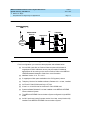
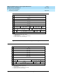
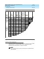
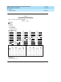
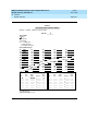
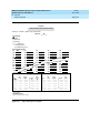
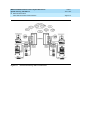
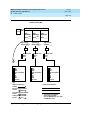
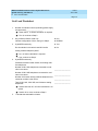
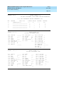
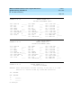
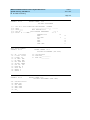
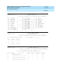
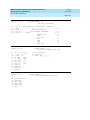
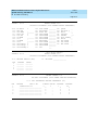
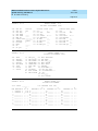
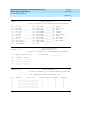
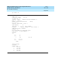
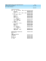
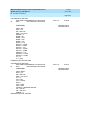
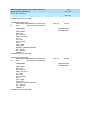
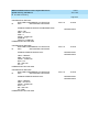
Refer to the completed Control Unit Diagram on Form 1 to mark line/trunk jack
types on Form 2c:
1.
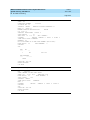
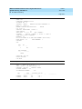
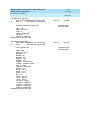
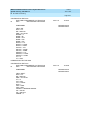
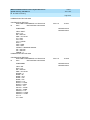
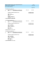
For each module with line/trunk jacks noted in the Control Unit Diagram
(beginning with Slot 01), write in the type of module and its slot number in
the Module Type and Slot No. column of Form 2c; after the appropriate
Log. ID number, draw a line to indicate the logical IDs (and therefore, the
line/trunk jacks) that correspond to that module.
If the system has 100D (DS1) modules, keep in mind that even though the
module has only one physical jack, the 100D module supports up to 24
endpoints. Therefore, 24 logical IDs and associated line/trunk numbers are
assigned to each module.
Likewise, the 800 NI-BRI module supports up to 16 endpoints or
extensions, therefore 16 logical IDs and associated line/trunk numbers are
assigned to each 800 NI-BRI module even thought the module has only
eight physical jacks.
2.
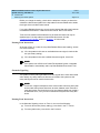
In the Jack Type column of Form 2c, for all modules except 100D modules,
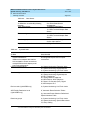
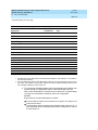
write the jack type for each logical ID. Use the codes shown in Table 3-2.
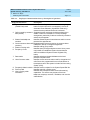
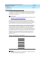
Table 3-2.
Codes for Line/Trunk Jacks
Jack Type Code
LS
GS/LS
DID
Tie
T1-GS
T1-LS
T1-Tie*
T1-DID
T1-S56
PRI
BRI
Line/Trunk Type
Loop-start
Ground-start/loop-start
DID
Tie
DS1 connectivity used to emulate GS
DS1 connectivity used to emulate LS
DS1 connectivity used to emulate tie or for digital data
service
DS1 connectivity used to emulate DID
DS1 connectivity used for digital data
DS1 connectivity used for PRI service
NI-1 BRI
*
T1 Switched 56 digital data is also available using T1-Tie trunks. See the ‘‘Tie Trunks’’
section later in this chapter.
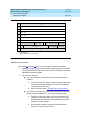
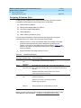
3.
For systems that include a 100D module, do one of the following in the
Jack Type column:
■
If the module will emulate trunks or will be used for digital data
transmission, write the appropriate jack type code (see Table 3-2)
for the channels being used (for example, T1-LS, T1-TIE, or T1-S56), or
write T1 if the channels are not being used at this time.