1
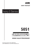
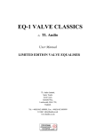
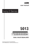
T L Audio
INDIGO SERIES
User Manual
VP-2051 VALVE
VOICE PROCESSOR
Tony Larking Professional Sales Limited,
Letchworth, England.
Tel: 01462 490600. International +44 1462 490600.
Fax: 01462 490700. International +44 1462 490700.
INTRODUCTION
The T L Audio Indigo Series combines classic valve techniques with low noise solid
state circuitry to produce audio processing units offering very high quality signal paths
with comprehensive control facilities and the unique valve sound.
The VP-2051 is a single channel valve voice processor, combining a high quality
microphone pre-amplifier, four band equaliser and a compressor. All parameters of the
compressor are variable, and a link facility enables two units to be operated in stereo
mode. The bargraph meter may be used to display output level or gain reduction.
The block diagram of the unit is shown in fig.1. Each channel has four input sources balanced microphone and line inputs via XLR connectors, plus an unbalanced line
level input via a jack socket, and an instrument input also on an unbalanced jack
socket but located on the front panel where it provides a convenient means of patching
a guitar or keyboard directly into the processor. The gain of the input stages is
controlled by a centre-detented control, calibrated for 0dB nominal gain from the line
input sources at the centre and providing up to 60dB of microphone gain. The
instrument input has a sensitivity switch associated with it, to match the gain to a low
level pickup (e.g. a passive guitar or microphone) or a higher output source such as a
keyboard or active guitar, and is also controlled by the input gain potentiometer.
The equaliser is fully valve based, providing up to 12dB of cut and boost at the
selected frequencies. The “EQ PRE” switch positions the equaliser before (pre) or
after (post) the compressor. The compressor comprises a valve core with solid-state
sidechain processing. The sidechain monitors the output of the compression stage, and
generates a control signal which varies the attenuation of the compressor. The
sidechain processing includes fully variable control of the compressor threshold and
ratio, plus switched fast and slow time constants for attack and release. Frequency
dependant compression (for example de-essing) may be achieved by placing an
equaliser into the sidechain insertion point.
An independent gain make-up control is provided, to retain the subjective loudness of
a compressed signal, plus an overall master output level control. The output control
has a nominal 0dB of gain at its centre, with up to 18dB of further gain available to
ensure full modulation of digital recorders. The output is via a balanced XLR socket at
a nominal level of +4dBu, with an unbalanced output on a jack socket at a nominal
level of -10dBu. An LED bargraph meter is provided, which may be switched to
monitor the output signal level or compression applied.
Please read this manual fully before installing or operating the Voice Processor.
PRECAUTIONS
The T L Audio VP-2051 Voice Processor requires very little installation, but like all
electrical equipment, care must be taken to ensure reliable, safe operation. The
following points should always be observed:
- All mains wiring should be installed and checked by a qualified
electrician,
- Ensure the correct operating voltage is selected on the rear panel
before connecting to the mains supply,
- Never operate the unit with any cover removed,
- Do not expose to rain or moisture, as this may present an electric
shock hazard,
- Replace the fuse with the correct type and rating only.
Warning: This equipment must be earthed.
INSTALLATION
AC Mains Supply.
The unit is fitted with an internationally approved 3 pin IEC connector. A mating
socket with power cord is provided with the unit, wired as follows:
Brown: Live.
Blue:
Neutral.
Green/Yellow: Earth (Ground).
All mains wiring should be performed by a qualified electrician with all power
switched off, and the earth connection must be used.
Before connecting the unit to the supply, check that the voltage selector switch on the
rear panel is correctly set. The unit may be set for 115V (accepting voltages in the
range 110V to 120V, 60Hz AC), or to 230V (for voltages in the range 220V to 240V,
50Hz AC). Adjustment to the operating voltage should be made by sliding the selector
switch left or right with a small screwdriver until the desired voltage is displayed. The
mains fuse required is 20mm anti-surge, 1AT rated at 250V. If it ever necessary to
replace the fuse, only the same type and rating must be used. The power consumption
of the equipment is 30VA.
Warning:
attempted operation on the wrong voltage setting, or with an
incorrect fuse, will invalidate the warranty.
Audio Operating Level.
The voice processor is equipped with inputs and outputs suitable for connection to a
wide variety of other audio equipment. Generally, the balanced XLR connections will
be required for interfacing to other professional equipment, where the operating level
(line-up level or nominal level) will be +4dBu, or approximately 1.2V rms. The
unbalanced jack connectors are generally intended for interfacing to semi-professional
equipment and have an operating level of -10dBu, or about 225mV rms.
The processor may be used to change between operating levels, for example by
connecting the unbalanced output of a semi-pro mixing console to the processor’s
unbalanced input, and taking the balanced output of the processor to the balanced
input of a tape machine at +4dBu. All line level inputs and outputs of the processor
may be used simultaneously if required. Balanced interconnection is always preferable
to obtain the best headroom and noise rejection, but can only be used if the other
equipment in the chain, e.g. the mixing console, also has provision for balanced
connections.
Audio Inputs.
Microphone Input.
The microphone input is via 3 pin female XLR connector, suitable for balanced or
unbalanced microphones. The mating connector should be appropriately wired as
follows for balanced or unbalanced operation:
Balanced inputs:
- Pin 1 = Ground (screen).
- Pin 2 = Signal Phase (also known as “+” or “hot”).
- Pin 3 = Signal Non-Phase (“-” or “cold”).
Unbalanced inputs:
- Pin 1 = Ground (screen)
- Pin 2 = Signal Phase (“+” or “hot”).
- Pin 3 = Signal Ground.
Line Input.
The line level input is also via a 3 pin female XLR connector, suitable for balanced or
unbalanced line sources at a nominal level of +4dBu. The mating connector should be
appropriately wired as follows for balanced or unbalanced operation:
Balanced inputs:
- Pin 1 = Ground (screen).
- Pin 2 = Signal Phase (also known as “+” or “hot”).
- Pin 3 = Signal Non-Phase (“-” or “cold”).
Unbalanced inputs:
- Pin 1 = Ground (screen)
- Pin 2 = Signal Phase (“+” or “hot”).
- Pin 3 = Signal Ground
When using unbalanced signals, the signal ground may be obtained by linking pins 1
and 3 in the mating XLR connector. If this connection is not made, a loss in level may
result.
Unbalanced Line Inputs.
An unbalanced line level input at a nominal level of -10dBu is also provided, on a
0.25” mono jack socket. The mating plugs should be wired as follows:
- Tip
= Signal Phase (“+” or “hot”).
- Screen = Ground.
Auxiliary Inputs.
A 2 pin (mono) jack plug is required, which should be wired as follows:
- Tip
= Signal Phase (“+” or “hot”).
- Screen = Ground.
The auxiliary input is suitable for direct connection of instruments including guitars
and keyboards. Good quality screened cable should be used, particularly for
microphone or low level sources, to prevent hum or noise pickup.
Insertion Point.
The insertion point is interfaced via a 3 pin, 0.25” switched jack socket on the rear of
the unit. The pin connections are:
- Sleeve = Ground,
- Tip
= Send,
- Ring
= Return.
The insertion point is unbalanced, and operates at a nominal level of -2dBu . If used
as an additional send only (e.g. as a send to a tape machine or monitor mixing desk),
the Tip and Ring should be wired together, to preserve the signal path through the
insertion point. When used in this manner, the send will be post-compressor.
Balanced Output.
The output is via a balanced, 3 pin male XLR connector. The mating connector
should be wired as follows:
- Pin 1 = Ground (screen),
- Pin 2 = Signal Phase (“+” or “hot”),
- Pin 3 = Signal Non-Phase (“-” or “cold”).
Unbalanced Output.
An unbalanced line output is provided for each channel, on a 0.25” mono jack socket.
- Tip =
Signal Phase (“+” or “hot”).
- Screen = Ground.
Link connection.
The compressor section stereo link facility is via an unbalanced jack socket. The
mating connector should be wired as:
- Tip =
Signal Phase (“+” or “hot”).
- Screen = Ground.
Note: The link signal is a DC control voltage. Do not connect the link socket to an
audio signal connector. It is only suitable for connection to the link socket on another
voice processor.
Ventilation.
The unit generates a small amount of heat internally. This heat should be allowed to
dissipate by convection through the grills in the side panels and top cover, which must
not be obstructed. Do not locate the unit where it will be subject to external heating,
for example in the hot air flow from a power amplifier, or on a radiator.
The voice processor may be free standing, or mounted in a standard 19” rack.
Rear Panel.
The rear panel connectors are identified in fig.3. Make sure that all settings, mains and
audio connections have been made as described above before attempting to operate
the equipment.
OPERATION.
Front Panel.
The front panel controls are identified in fig.2.
Pre-Amplifier section.
Phantom Power.
+48V Phantom power may be applied to the microphone input socket by depressing
the “+48V” switch on the front panel. Phantom power should only be used with
suitable microphones (i.e. condenser microphones).
WARNING:
Always turn the master output level to minimum before
switching phantom power on or off, and before
connecting or disconnecting a microphone. Failure to set
the level to minimum may result in a loud click or
thump in your monitor loudspeakers.
Microphone Input.
When using the voice processor with a microphone input, care should be taken not to
apply too much gain at the input. Start with the input gain control set to minimum, and
the output master at the mid-point (12 o’clock position). The input gain can then be
gradually increased until the peak LED illuminates on the loudest peaks only. The
master output level should then be adjusted to produce the required output.
Line Input.
A line level signal should already be at about the correct operating level, but this may
be checked by bypassing the compressor (i.e. turning off the COMP IN switch) and
monitoring the level on the bargraph meter. The input gain should be adjusted until the
0dB LED is illuminated on music of normal loudness, with the red LEDs illuminating
occasionally on higher volume peaks.
Aux Input.
The front panel auxiliary input sockets may be switched between high level signals
(“LO GAIN”, suitable for active guitars and keyboards) and low level signals (“HI
GAIN”, suitable for microphones, pick ups or passive guitars), and are also controlled
by the input gain control.
LF Cut Filter.
The voice processor is equipped with high pass (low frequency cut) filter, which may
be used to remove unwanted low frequencies from the input signal. It is effective in
reducing hum, rumble caused by traffic or wind noise, and excessive LF signal content
from close mic applications.
Phase Reverse.
The phase reverse switch changes the polarity of the input signal. The effect is not
apparent with a single microphone setup, but is essential to correct any phase error in
a stereo application, or where the processor is patched into the insertion point of a
mixing console. A phase error typically appears as an apparent loss of bass.
Compressor Section.
Compressor Operation.
A compressor functions by reducing the gain of the signal when it exceeds a certain
level, or threshold. The amount of gain reduction may be fairly gentle through to
limiting, where the signal is clamped at the threshold level. The amount of gain
reduction is determined by the ratio control, which is calibrated as a ratio of the
output to input signals.
The gain of the signal is reduced by a voltage-controlled circuit. Variable time
constants are applied to the control voltage to adjust the rate at which the gain is
reduced, called the attack time, and the rate at which unity gain is restored after the
signal returns to below the threshold, referred to as the release time.
The effect of compression is to limit the dynamic range of a signal. It may be used to
keep a variable output from a bass guitar, for example, at an even level, or to add
punch to vocals, drums, guitar or a complete mix.
Whist the subjective sound quality can be improved by compression, the overall signal
level may be reduced. A gain make-up control at the output of the compressor stage
allows the signal level to be brought back to the same loudness as the uncompressed
signal.
Frequency selective compression may be obtained by inserting an equaliser into the
sidechain signal, from which the control voltage is generated. Boosting a range of
frequencies will have the effect of lowering the compressor threshold at those
frequencies; i.e. making the compressor more sensitive. Note that the equalisation is
not applied to the audio output, but is used to modify the control sidechain. A common
use of sidechain equalisation is “de-essing” to reduce sibilance on vocals. Suitable
equalisers which can be inserted into the sidechain are the TL Audio Indigo Series
2011 or 2012 valve equalisers, which match the 2051 in audio levels and styling.
Threshold.
The 2051 compressor section has a variable threshold, set by a rotary control
calibrated from +20dBu to -20dBu, resulting in increased compression as the control
is rotated clockwise.
Attack and Release.
The attack time is switchable to 0.5msec or 20msec. At 0.5msec attack, the
compressor is fast enough to reduce the gain of a 1KHz signal in less than half a cycle,
effectively preventing an overload of any following equipment which has limited
headroom, such as a digital processor, tape machine or transmitter.
The release time is switchable to 40msec or approximately 2 seconds. Adjustment of
the attack and release times allows unobtrusive compression to be applied to virtually
any audio signal, but should very short transients occur the time constants become
signal dependant, generally reduced, to prevent a slow release leaving a “hole” in the
signal after the transient. Also, a fast release setting will be extended by a slow attack
setting. Due to this automatic modification of the time constants, the controls are
simply calibrated “fast” and “slow”.
Ratio.
The ratio may be varied from 1:1.5 (very gentle compression) to 1:30 (near limiting).
The compressor normally operates with a “soft-knee”, i.e. the compression is
gradually introduced as the signal passes the threshold, in which case the ratio refers
to the compression eventually obtained.
Gain Make-Up.
Up to 20dB of gain make-up may be applied, to retain the subjective loudness of the
signal.
Bypass.
The Compressor In switch allows the processing to be bypassed for comparison of the
compressed signal (with any gain make up that has been applied), with the original
signal.
Stereo Operation.
Two 2051 voice processors may be configured for stereo operation of the compressor
section by inserting a Link cable between the two units. In this mode, the control
voltages are linked, ensuring that the same amount of gain reduction is applied to both
channels (even if one signal is below the threshold). This ensures that the stereo image
is preserved. To active this mode, the Stereo Link switch should be depressed on both
2051’s.
Ducking or Gating.
A variation on stereo operation as described above is master-slave operation, where
the gain of one 2051 is controlled from another unit, but without reciprocal action.
This is useful where a voice channel input is required to reduce the gain of, for
example, background music when the microphone signal is present.
The link cable should be fitted, as for stereo operation, but the Stereo Link switch
should only be depressed on the “slave” 2051 (the backgound music channel in the
example above). If the compressor is switched out on the master unit, gain reduction
will only occur on the slave unit. The threshold and ratio controls on the master 2051
will determine the extent of the gain reduction in the slave unit.
Equalisation.
The 2051 equaliser section has four bands, each with continuously variable cut and
boost control and switched frequency selection. Each band has a filter with a relatively
low “Q” of approximately 0.5, with a broad control range and moderate overlap
between the bands.
LF Band.
The LF (Low Frequency) band of the equaliser has a shelving characteristic - i.e. it
extends from the selected frequency to the extreme low frequency limit of the
equaliser’s response.
The corner frequency of the LF band is selected by a push button to 120Hz or 80Hz,
and the cut or boost is controlled by a continuously variable, centre-detented rotary
knob. At the selected corner frequency, up to 12dB of cut and boost are available.
Typical response curves are shown in the specification section of this manual.
LM Band.
The LM (Low-Mid Frequency) band has a peaking characteristic - i.e. it boosts or cuts
a section of the audio spectrum around its selected centre frequency only.
A four position rotary switch is used to select the centre frequency to 250Hz, 500Hz,
1KHz or 2K2Hz. The mid bands possess a low Q, wide bandwidth, response which
results in effective equalisation without harshness, and this means that there is a good
degree of overlap between the frequency options.
The amount of cut or boost is again controlled by a continuously variable, centredetented rotary knob, with up to 12dB of cut and boost available at the centre
frequencies. Response curves for the mid bands are also shown in the specification
section of this manual.
HM Band.
The HM (High-Mid Frequency) band is similar in operation to the LM band, except
that the centre frequencies are obviously higher, and concentrated in the critical upper
vocal region of the spectrum. The available frequencies are 1K5Hz, 2K2Hz, 3K6Hz
and 5KHz.
HF Band.
The HF (High Frequency) band has a shelving characteristic, complimenting the LF
band. Corner frequency selection is by push switch to 8KHz or 12KHz.
Bypass.
The Equaliser In switch allows the processing to be bypassed for comparison of the
equalised and original, unprocessed signal.
EQ Pre.
The pre switch places the equaliser ahead of the compressor section. Depending on the
EQ settings, the compressor response will be modified. The effect may be compared
by toggling the pre switch.
Master Section.
Master Level.
The master level control is an output fader, which enables the voice processor output
to be matched to the following equipment. The control is calibrated for 0dB at its
centre, with a further 18dB of gain available by turning the knob fully clockwise. The
additional gain may be useful if the output of the voice processor is connected directly
to a digital recorder which requires a high level of modulation. Note that applying
additional gain at the output will not increase the dynamic range of the signal, but will
increase the noise level as well as the audio signal being recorded, and should
therefore only be used if an output level in excess of the nominal +4dBu is required.
Bargraph Meter.
The processor is equipped with an 8 segment LED bargraph meter. The meter
normally monitors the audio output from the unit, and is calibrated for nominal level
of +4dBu at the balanced output = 0dB. Similarly, 0dB on the meters also corresponds
to -10dBu at the unbalanced output. The reference point may be internally adjusted by
your dealer if required. The output level scale is printed above the bargraph.
The meter may be switched to indicate the amount of compression applied to the
signal, by operating the GAIN RED’N switch. If the signal is below the threshold, the
meter will not illuminate: i.e. no gain reduction is occurring. As the signal passes
through the threshold the 0dB LED will illuminate, indicating that gain reduction has
started. For further increases in input level, the meter will indicate the gain reduction
occurring at the compressor stage. Note that the gain reduction indicated is a measure
of the degree of compression, and does not include any gain make-up applied. The
gain reduction scale is printed beneath the meter.
SPECIFICATIONS
Microphone Input:
Electronically balanced.
Input impedance greater than 2Kohm.
Gain range +10dB to +60dB.
Noise -127dBu (EIN with 150 ohm source, 22Hz - 22KHz and
maximum gain).
3 pin female XLR connector.
Phantom Power:
+48V at 10mA maximum per microphone.
High Pass Filter:
-3dB at 90Hz, 12dB per octave.
Balanced Line Input:
Electronically balanced, unbalanced compatible, with input
impedance greater than 5Kohm.
Gain range -20dB to +20dB.
Nominal input level +4dBu.
Maximum input level +26dBu.
3 pin female XLR connector.
Unbalanced Input:
Input impedance greater than 5Kohm.
Gain range -20dB to +20dB.
Nominal input levels -10dBu.
Maximum input level +12dBu.
2 pole 0.25” jack socket.
Auxiliary Input:
Switchable for high or low gain, plus 40dB gain variation.
Maximum input level +18dBu.
2 pole 0.25” jack socket.
Compressor:
Threshold -20dBu to +20dBu,
Attack 0.5msec or 20msec,
Release 40msec or 2 seconds,
Ratio 1:1.5 to 1:30,
Gain Make-Up 0 to +20dB.
Equaliser:
LF Band:
+/-12dB at 80Hz or 120Hz.
Shelving response.
LM Band:
+/-12dB at 250Hz, 500Hz, 1KHz or 2K2Hz.
Peaking response, Q = 0.5.
HM Band:
+/-12dB at 1K5Hz, 2K2Hz, 3K6Hz or 5KHz..
Peaking response, Q = 0.5.
HF Band:
+/-12dB at 8KHz or 12KHz.
Shelving response.
Bargraph Meter:
Switchable to output level or compression,
0dB = +4dBu.
Output Fader:
Rotary fader, 0dB at centre, +18dB maximum gain.
Outputs:
Electronically balanced, unbalanced compatible.
Output impedance 47 ohms.
Maximum level +26dBu.
3 pin male XLR connector.
Unbalanced Outputs:
Output impedance 47 ohms.
Maximum level +18dBu into 10Kohms.
2 pole 0.25” jack socket.
Frequency Response:
10Hz to 40KHz, +0, -1dB.
Dynamic Range:
108dB (Line input @ 0dB gain).
Sidechain Insertion Points:
Unbalanced, switched 3 pin jack socket, tip = send,
ring = return.
Nominal level -2dBu.
Output impedance 47 ohms.
Return input impedance 10Kohms.
Power Requirements:
Rear panel selectable for 220-240V 50Hz or 110-120V 60Hz
operation.
Rear panel fuse 20mm, 1AT, 250V.
Power consumption 30VA typical.
Detachable 3 pin IEC connector, mating connector and cable
supplied.
Front panel On/Off switch with green LED.
Dimensions:
19” rack mounting, 1U high.
483mm wide x 44mm high x 250mm deep.
Weight:
4Kg.
The above specifications are subject to change without notice.
SERVICE
Should the processor require service, it must be taken or posted to an authorised
dealer. Please retain the original packing for possible future use, and ensure the unit is
suitably protected during transit. The manufacturer cannot accept responsibility for
damage caused during transportation.
The processor is supported by a limited warranty for a period of one year from the
date of purchase. During this period, any faults due to defective materials or
workmanship will be repaired free of charge. The warranty excludes damage caused
by deliberate or accidental misuse, operation on the incorrect mains voltage, or
without the correct type and value of fuse fitted. It is the user’s responsibility to ensure
fitness for purpose in any particular application. The warranty is limited to the original
purchase price of the equipment, and excludes any consequential damage or loss.
Please retain proof of purchase, and record the following details:
Serial Number.............................
Date purchased...........................
Dealer.........................................