1
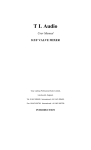
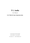
®
TLAudio
user manual
Ivory 2 Series
5051
MONO VALVE PROCESSOR
TL Audio Ltd, Letchworth, Herts, SG6 1AN, UK
email: [email protected] web: http://www.tlaudio.co.uk
CONTENTS
1
INTRODUCTION
2
PRECAUTIONS
3
INSTALLATION
3.1
3.2
3.3
3.4
3.5
3.6
3.7
3.8
A.C. Mains Supply
Microphone Input
Balanced Line Input
Unbalanced Line Input
Instrument Input
Outputs
Nominal Operating Level
Ventilation
4
OPERATION
4.1
4.2
4.3
4.4
4.5
4.6
4.7
4.8
4.9
4.10
4.11
4.12
4.13
4.14
4.15
4.16
4.17
Input Stage
What is Compression?
Why Valve Compression?
Overview of Compressor Operation
Threshold
Ratio
Attack and Release
Knee
Gain Make Up
Meter
Compressor On
Gate
EQ Section
EQ Pre
Output Gain
Stereo Link
DO-2 Digital Output Option
5
GETTING STARTED
5.1
5.2
5.3
Connection
In Use
Frequently Asked Questions (FAQ)
6
SPECIFICATIONS
7
SERVICE
1.
INTRODUCTION
Congratulations on purchasing the Ivory 5051 Mono Valve Processor by TL
Audio!
The Ivory Series consists of a range of hybrid valve signal processors, which
utilise low noise solid state electronics in conjunction with classic valve
circuitry to produce audio processing units offering very high quality signal
paths with the unique valve audio character. The units offer comprehensive
control facilities, whilst remaining straightforward to operate, and represent
excellent value for money.
The 5051 is a single channel voice and instrument processor with mic, line
and instrument inputs, a compressor, a four band equaliser and a noise gate.
A single illuminated VU meter monitors the input level, output level or the
compressor gain reduction. The optional DO-2 digital output card allows 24-bit
analogue to digital conversion via an RCA phono type SPDIF output, with
selectable 44.1 or 48 kHz sample rates and the option to clock the converter
to an external word clock source.
The block diagram of the 5051 is shown in Figure 1. A solid state,
electronically balanced input amplifier is used to achieve state of the art
performance with very low noise, low distortion and wide bandwidth. An
ECC83/12AX7A triode valve stage (run from a stabilised 150v DC supply) is
used as a second stage voltage amplifier, to obtain the classic valve sound
and gradual overdrive characteristics.
The preamp stage also features 48V phantom power, a 30dB pad and a high
pass 90Hz filter. A Drive LED gives a visual indication of the signal level
through valve stages (and thus the amount of ‘warming’ taking place) while a
Peak LED warns that clipping is about to occur, and this monitors the signal at
key points in the audio path.
The compressor section offers fully variable control of threshold, ratio and gain
make-up, with four switchable attack and release times and both hard and soft
knee options. A ‘Hold’ facility reduces LF distortion, and a side chain insert
point is provided for frequency conscious compression. Like all other TL Audio
compressors, the gain control element of the 5051 compressor stage is based
around a special transconductance amplifier, which avoids the use of VCAs
and helps contribute to the smooth, open sound of the unit. A stereo link
facility is provided to allow the compressor control voltages of two 5051s to be
linked, thus preventing image shift when processing stereo signals.
A four band valve EQ stage is included, providing up to 12dB of cut or boost
and a choice of four pre-selected frequencies on each band. The ‘EQ PRE’
switch places the EQ ahead of the compressor in the signal path. A simple but
effective noise gate (with variable threshold) is provided to remove unwanted
background noise.
Mic and line inputs are provided on electronically balanced XLR connectors,
and the line input is duplicated on an unbalanced mono 0.25” jack connector.
Balanced and unbalanced line outputs are provided (on XLR and jack
respectively) and these can be used simultaneously. The operating level of the
line input can be shifted from -10dB to +4dB (unbalanced) or +4dB to +18dB
(balanced) via a rear panel switch, allowing the 5051 to accept very high levels
- such as those from a digital recorder. A front panel instrument input is also
provided, thus allowing guitars, basses and keyboards to feed directly into the
5051, removing the need for a separate DI box.
Please read this manual fully before installing or operating the 5051.
2.
PRECAUTIONS
The Ivory 5051 requires very little installation, but like all electrical equipment,
care must be taken to ensure reliable, safe operation. The following points
should always be observed:
- All mains wiring should be installed and checked by a qualified
electrician,
- Ensure the correct operating voltage is indicated on the rear panel
before connecting to the mains supply,
- Never operate the unit with any cover removed,
- Do not expose to rain or moisture, as this may present an electric
shock hazard,
- Replace the fuse with the correct type and rating only.
Warning: This equipment must be earthed.
3.
INSTALLATION
3.1
AC Mains Supply.
The unit is fitted with an internationally approved 3 pin IEC connector. A
mating socket with power cord is provided with the unit, wired as follows:
Brown: Live.
Blue:
Neutral.
Green/Yellow: Earth (Ground).
All mains wiring should be performed by a qualified electrician with all power
switched off, and the earth connection must be used.
Before connecting the unit to the supply, check that the unit is set for the
correct mains voltage. The unit is internally set for 110-120V 60Hz or 220240V 50Hz operation, and should only be changed by an authorised service
centre. The mains fuse required is 20mm anti-surge, 1AT rated at 250V. If it
ever necessary to replace the fuse, only the same type and rating must be
used. The power consumption of the equipment is 30VA.
Warning: attempted operation on the wrong voltage setting, or with an
incorrect fuse, will invalidate the warranty.
3.2
Microphone Input.
The microphone input is via 3 pin female XLR connector, suitable for balanced
or unbalanced microphones. The mating connector should be appropriately
wired as follows for balanced or unbalanced operation:
Balanced inputs:
- Pin 1 = Ground (screen).
- Pin 2 = Signal Phase (also known as “+” or “hot”).
- Pin 3 = Signal Non-Phase (“-” or “cold”).
Unbalanced inputs:
- Pin 1 = Ground (screen)
- Pin 2 = Signal Phase (“+” or “hot”).
- Pin 3 = Signal Ground.
3.3
Balanced Line Input.
The 5051 has a 3 pin XLR socket on the rear panel, which will accept both
balanced and unbalanced line level inputs. The mating connector should be
appropriately wired as follows:
Balanced inputs:
- Screen = Ground,
- Tip = Signal Phase (“+” or “hot”),
- Ring = Signal Non-Phase (“-” or “cold”).
Unbalanced inputs:
- Screen = Ground,
- Tip = Signal Phase (“+” or “hot”),
- Ring = Ground.
When using unbalanced signals, the signal ground may be obtained by linking
pins 1 and 3 in the mating XLR connector. If this connection is not made, a
loss in level may result.
3.4
Unbalanced Line Input.
An unbalanced line level input at a nominal level of -10dBu is also provided,
on a 0.25” mono jack socket. The mating plugs should be wired as follows:
- Tip
= Signal Phase (“+” or “hot”).
- Screen = Ground.
3.5
Instrument Input.
Each channel has a 0.25” jack socket on the front panel (see Figure 2). A 2
pin (mono) jack plug is required, which should be wired as follows:
- Tip = Signal Phase (“+” or “hot”),
- Screen = Ground.
3.6
Outputs.
The output is an xlr balanced output and also an unbalanced ¼” jack on the
rear panel. Balanced operation is always preferable to maintain maximum
headroom and signal to noise ratio, but can only be used if the following
equipment is also capable of balanced operation:
Balanced outputs:
- Screen = Ground,
- Tip = Signal Phase (“+” or “hot”),
- Ring = Signal Non-Phase (“-” or “cold”).
Unbalanced outputs:
- Screen = Ground,
- Tip = Signal Phase (“+” or “hot”),
- Ring = Ground.
3.7
Nominal Operating Level.
A switch on the rear panel allows the line inputs to be matched to equipment
at a nominal operating level of +4dBu or -10dBu for unbalanced signals and
+18dBu or +4dBu for balanced signals. Most professional equipment requires
+4dBu (approximately 1.2V rms), but some small mixing consoles, portable
tape recorders or domestic audio equipment require -10dBu (approximately
225mV rms). Digital multitrack recorders have very high signal levels due to
the digital scale of 0dBFS usually matching +18dBu in the analogue domain.
The 5051 is able to match the operating level of such recorders. If the
operating level is not known, the switch should be set to the position which
FIG 2: FRONT PANEL
EQUALISER FREQUENCY
SWITCH
INPUT SELECTOR SWITCH
INPUT
MIC
COMPRESSOR
ATTACK
LINE
MIC
48V
SLOW
INST
EQUALISER
RELEASE
FAST
120
SLOW
FAST
60
HARD
SOFT
MIC
-30dB
INPUT
IVORY
LINE 0dB
THRESHOLD
0
RATIO
1:5
1:10
INSTRUMENT
GAIN
MAKE-UP
5
500
500
METER
2K2
2K2
3K6
1K5
Hz
5K
5K
LM
0
8K
2K2
Hz
LF
0
GATE
-40
1K
250
Hz
KNEE
12
250
VU METER
O/P
12K
O/P+10
G/R
I/P
5051
Hz
HM
0
HF
0
MONO VALVE
PROCESSOR
OUTPUT
0
-20
EQ
ON
16 dB 60
DRIVE
90Hz
+20 dB
-20
1:1.5
1:30
0
OFF dB -10
dB 20
PEAK
COMP
ON
INSTRUMENT INPUT
COMPRESSOR CONTROLS
INPUT GAIN CONTROL
-12 dB +12
-12 dB +12
-12 dB +12
-12 dB +12
EQ
PRE
LINK
- oo dB +15
SHUT
POWER
GATE
THRESHOLD
CONTROL
EQUALISER
CUT/BOOST
CONTROL
OUTPUT LEVEL CONTROL
FIG 3: REAR PANEL
SAMPLE RATE SELECTOR SWITCH (OPTIONAL)*
DIGITAL OUTPUT (OPTIONAL)*
WARNING - ATTENTION
THIS APPARATUS MUST BE EARTHED.
FOR CONTINUED PROTECTION
AGAINST RISK OF FIRE, REPLACE ONLY
WITH SAME TYPE AND RATING OF FUSE.
UTILISER UN FUSIBLE DE RECHANGE DE
MEME TYPE ET CALIBRE
W/CLOCK INPUT (OPTIONAL)*
SPDIF OUTPUT
RISK OF ELECTRIC SHOCK
DO NOT OPEN
5051 MONO VALVE PROCESSOR
ATTENTION
kHz
44.1
Manufactured by TL Audio Limited, England.
CAUTION
W/CLOCK
IN
48
SERIAL NUMBER
RISQUE DE CHOC ELECTRONIQUE
NE PAS OUVRIR
+4dBu
BALANCED
OUTPUT
INSERT: TIP = SEND, RING = RETURN,
BALANCED INPUT
MIC INPUT
SLEEVE = GND.
FUSE T1AL 250V
230V~25VA
115V~25VA
WARNING
TO REDUCE THE RISK OF FIRE
OR ELECTRICAL SHOCK,
DO NOT EXPOSE THIS EQUIPMENT
TO RAIN OR MOISTURE
-10dBu
UNBALANCED
S/CHAIN
INSERT
LINK
JACK: TIP = +VE, SLEEVE = GND.
LINK: TIP = +VE, SLEEVE = GND.
NOTE: CONNECT TO SECOND 5051
LINK SOCKET ONLY.
XLR: PIN 1 = GND, PIN 2 = +VE, PIN 3 = -VE.
IEC INLET
LINE OUTPUTS
SIDECHAIN INSERT
POINT CONNECTOR
* VIA DO-2 DIGITAL OUTPUT CARD
INPUT
LEVEL
UNBALANCED
INPUT
-10dBu
+4dBu
+4dBu
+18dBu
INPUT LEVEL SWITCH
STEREO LINK CONNECTOR
INPUTS
results in the best signal to noise ratio and least noise while being able to
handle high signal levels.
3.8
Ventilation.
The 5051 generates a small amount of heat internally, mainly due to the valve
heater. This heat should be allowed to dissipate by convection through the
side grills, which must not be obstructed. Do not locate the 5051 where it will
be subject to external heating, for example, in the hot air flow from a power
amplifier or on a radiator.
4.
OPERATION
4.1
Input Stage.
The Input Gain control sets the level of the signal whether mic, line or
instrument into the 5051. The signal source is selected by the 4-position
switch above the Input Gain knob. Input choices are Mic 48v (for condenser
microphones that require phantom power), Mic (for dynamic or most ribbon
microphones), Line and Instrument. The Instrument input allows high
impedance instruments such as guitars or a bass etc to connect directly into
the 5051 and eliminates the need for a Direct Injection Box. A wide range of
signals can be fed into the 5051, and the Input Gain control also allows the
valve stages to be driven to a variable degree. After the preamp stage the
signal passes through a triode valve stage positioned between the input circuit
and the compression stage. Increasing the input gain pushes more signal level
into the valve, thus generating more harmonic distortion and creating that
special “valve sound”. This is indicated by the yellow drive led which will glow
more intensely as the level increases. At the same time the output level can
be turned down to preserve the same level at the outputs, so a choice of
sounds is available. For a more pronounced valve sound, turn up the input
gain and reduce the output gain, and vice versa for a cleaner sound. Don’t be
afraid to push the 5051 hard!
As well as driving the valves harder, increasing the Input Gain control
will also have a pronounced effect on the amount of compression
threshold will remain constant as the input level increases. If the input
adjusted the threshold can be adjusted accordingly to maintain a
amount of compression.
4.2
setting
as the
gain is
similar
What is Compression?
Compression is an essential but often misunderstood process in modern
recording. Put simply, compression reduces the difference between the
loudest and the quietest levels of an audio signal. This is known as reducing
the “dynamic range” of that signal and is a powerful tool for an engineer
helping to avoid overloading, distortion problems as well as raising the level of
the quieter parts of the audio signal. Before the introduction of compressors
the only way this could be achieved was by “gain riding”, whereby an engineer
would control the fader manually in order to try and anticipate very large levels
(which might distort the signal) or very low levels (which may get lost in noise).
The introduction of compression devices meant that this process could be
controlled automatically, allowing the engineer to get on with more productive
jobs!
Many instruments and voices have a very wide dynamic range that need to be
controlled. A singer, for instance, may be singing quietly one moment and very
loudly the next, and unless compression is applied the vocal won’t “sit”
correctly in the mix, in addition to the problems of distortion on loud passages
and noise on quiet ones. Compressors effectively turn down the loud bits and
turn up the quiet bits, to achieve a more even and controllable level.
Compressors are often judged by their ability to control the dynamics without
creating noticeable audible side effects. Heavy compression can cause the
signal to pump or breathe with the onset and release of the compression.
Some compressor designs can dull the signal and lose the top end of the
signal. The 5051 compressor design, as with other TL Audio compressors,
uses a technology based around a transconductance amplifier rather than a
VCA design. This transconductance amplifier design is known for being able to
retain the full frequency range and natural character of the audio signal, even
when compressing the signal quite heavily. The Ivory 2 5051 is also capable of
more severe compression based around the optional Hard Knee mode if this is
desired.
There are other benefits of compression as well as just controlling the peaks
and raising the quiet parts, applied properly, it can add punch and excitement
to music, as well as fattening up sounds and creating a more professional
sounding recording. With the 5051, you have the added benefit of valve stages
in the signal path, which create a warmth and presence just not obtainable
with solid state or digital products.
4.3
Why Valve Compression?
Valve compression yields a particularly special sound which has become very
sought after, particularly with the widespread use of digital products. The
reason valve equipment sounds special is due to two things: harmonic
distortion and natural compression. When the signal through a valve is
increased, it tends to generate a particular type of subtle and desirable
distortion, called “second harmonic” distortion. This has the effect of thickening
and warming the sound, and the more the level you feed to the valve stages,
the more of this harmonic distortion will be produced. You should be able to
hear this effect as you increase the Input Gain on the 5051.
Secondly, valves will tend to naturally compress an audio signal, again
particularly as the signal level is increased. This itself also contributes to the
warmth produced by the 5051.
4.4
Overview of Compressor Operation.
To operate the 5051 successfully an understanding of each control will help to
obtain the best results. If you are unfamiliar with the effect of compression it
may help to adjust the controls to extreme settings and listen to the sonic
effect. Compressors can either be used to enhance the signal and control the
dynamic range with as little sonic effect as possible, or they can be used more
severely specifically for effect.
4.5
Threshold.
The Threshold is the point measured in decibels that any compression comes
into operation. The Threshold control is variable from +20dB in the most
anticlockwise position to -20dB at the most clockwise position. Any signal
below the Threshold passes through the unit unaffected; while signals above
the Threshold are reduced in gain (and are thus ‘compressed’). This does
depend on the Soft or Hard knee to some extent as the Soft knee is more
gradual around the Threshold point.
Unlike some compressors, the Threshold control on TLA units including the
5051 starts at a ‘plus’ value in the counter-clockwise position, and decreases
to a ‘minus’ value as you rotate the control clockwise. The reason for this is as
you turn the Threshold control on the 5051 clockwise (i.e. towards the
negative region) then the degree of compression will increase. We think this is
logical, whereas the common method of turning the control ‘down’ to achieve
more compression is not - but beware, some other compressors may work in
the opposite direction!
4.6
Ratio.
Once the input signal has crossed the threshold, the degree of gain reduction
is determined by the Ratio control. The Ratio control is calibrated in decibels
and is simply the change in output level that results from a given change in
input level. An uncompressed signal will have a 1:1 compression ratio - every
1dB change in input level results in the same 1dB change in output level. A
compression ratio of 1:3, for instance, means that a 3dB change in input level
will only give a 1dB change in output level. For more severe compression,
simply turn up the Ratio control.
The 5051 offers a wide range of ratios from 1:1.5 (gentle compression)
through to 1:30 (limiting). Limiting effectively clamps the input signal at the
threshold level no matter how much the signal is increased: this can be useful
when trying to ensure that the signal doesn’t exceed a certain level - for
instance to prevent a digital recorder distorting through overload.
4.7
Attack and Release.
The Attack and Release settings allow a choice of four positions between slow
and fast. The Attack is how quickly the compression is applied once the
Threshold has been exceeded. The Release is how quickly the compression is
released. There is an element of automatic Attack and Release on the 5051 to
cope with sudden transient signals. The speed of the Attack and Release
should be able to work with the tempo of the signal. For example if the signal
is a snare drum, by monitoring the gain reduction it is possible to set the
Release to allow the compression to fully recover (the gain reduction needle
will settle back to 0dB) before the following snare beat. This prevents the
oncoming snare beat from having a reduced gain to the first snare beat. One
side effect of having an incorrect Release setting is distortion on low frequency
signals. This is due to the Release changing gain to quickly for the large low
frequency waveforms. To cure this problem the Release can be slowed down.
4.8
Knee.
The Knee switch enables the 5051 to be operated in two different modes - Soft
Knee or Hard Knee. Soft Knee mode offers a gentle compression curve
around the Threshold point, and is traditionally employed to yield a more
subtle, musical type of compression effect. The Hard Knee setting causes the
full compression ratio to be applied immediately the signal has passed the
Threshold point, so tends to produce more pronounced and severe
compression.
4.9
Gain Make Up.
While the subjective sound quality of the signal can be improved by
compression, the overall signal level will be reduced when gain reduction is
taking place. The Gain Make Up control is designed to boost the compressed
signal by between 0 and 20dB, in order to bring back the level to the same
loudness as the uncompressed signal. Without this control, comparing the
original and compressed signals becomes difficult, since there would be a
level drop each time the compressor is switched in: therefore it is normal to
adjust the Gain Make Up control so that when the ‘compressor on’ switch is
activated, the audio signal remains constant in level.
Unlike the Output Level control, the Gain Make Up control is active only when
the ‘compressor on’ switch is engaged. Once the Gain Make Up has been
adjusted, use the Output Level control to set the overall output level of the
5051.
4.10
Meter.
The 5051 is equipped with an illuminated VU meter. The Meter switch enables
the 5051 VU meter to monitor each one of four parameters. When switched to
‘Input’ the meter reads the audio input level. When switched to ‘Output’ the
meter reads the audio output level, and is calibrated to read 0VU for a +4dBu
output level. When switched to ‘Output + 10’ the meter reads 10dB below the
audio output level. Increasing the Output Level control on the 5051 towards
the +15dB setting will cause the 5051’s meter to move further towards the red
area and possibly to the end of the scale if sufficient gain is applied. The
‘Output +10’ setting can be selected to prevent the VU needle from pressing
constantly at its end stop. This is normal, particularly if driving a digital
recorder where large input levels are required. The meter when switched to
‘GR’ (Gain Reduction) indicates the amount of compression occurring. If the
signal is below the threshold, the meter will indicate 0dB: i.e. no gain
reduction. As the signal passes through the threshold, the meter will start to
indicate the gain reduction at the compressor stage (this will be a negative
value, so the meter will move to the left, away from 0VU). Note that this
reading won’t include any extra gain make-up applied.
4.11
Compressor On.
This switch enables or disables the compressor stage, thus allowing an A/B
comparison to be made between the original untreated signal and the
compressed signal. An associated status LED indicates when the compressor
is active. The 4th position Gain Reduction on the VU meter will monitor the
level of compression regardless of the compressor stage being active or non
active.
4.12
Gate.
What is a gate and how do I use one?
A gate (or noise gate) is a device that can completely shut off or mute the
signal path. The point at which the 5051 gate will shut is based on the level of
the signal falling below an adjustable threshold point. Gates are commonly
used to shut out background noise or hiss from noisy signals or to isolate a
louder signal from other quieter signals. An example of this would be when
miking up a drum kit with a number of individual mics on specific drums. Each
mic will pick up not only the drum it is directly miking but also all the
neighbouring drums. By gating out the quieter neighbouring drums each drum
track can be “cleaned up”. The trick to using the gate successfully is to adjust
the threshold to the point where the desired signal opens the gate and the
undesirable signal is below the threshold point and is gated out. This is never
an easy task as the threshold point remains constant but the point between
desirable signal and undesirable signal is constantly changing. Gating can be
a tricky process to get right as success depends a great deal on the signal
characteristics.
The gate on the 5051 is situated before the compressor stage and has a red
led indicating when the gate is active or shut. At fully anti-clockwise the gate is
at its off position and is completely inactive. Turning the gate clockwise
towards the -10dB maximum setting raises the threshold point so that the
signal needs to be increasingly louder (as the threshold is raised) to open the
gate. At the lowest setting, just above the off position, low level signals such
as background noise can be gated. Raising the threshold point by turning the
gate control clockwise allows gating of higher level signals such as drums. If
you are having trouble selecting the threshold point one tip is to select different
threshold points suitable for specific parts of the signal and mark them with a
chinograph pencil. For example the intro to the signal may be quite strong so
the threshold can be set quite high and the end of the signal may have a
gradual fade out so the threshold can be adjusted to suit this ending. This of
course is only possible with recorded signals where the track can be
constantly replayed to practice the settings.
4.13
Equalisation.
The 5051 equaliser section has four bands, each with continuously variable
cut and boost control. Each band has a four position switch to select the
nominal corner frequency for the shelving bands (LF and HF), or centre
frequency for the peaking mid-bands. The Q or bandwidth of the equalisers is
approximately 0.5, allowing a good degree of overlap between bands.
LF Band.
The LF (Low Frequency) band of the equaliser has a shelving characteristic i.e. it extends from the selected frequency to the extreme low frequency limit
of the equaliser’s response.
The corner frequency of the LF band is selected by a rotary switch from 60Hz
to 500Hz, and the cut or boost is controlled by a continuously variable, centredetented rotary knob. At the selected corner frequency, up to 12dB of cut and
boost are available. Typical response curves are shown in the specification
section of this manual.
LM Band.
The LM (Low-Mid Frequency) band has a peaking characteristic - i.e. it boosts
or cuts a section of the audio spectrum around its selected centre frequency
only. The centre frequency of the LM band is selected by a rotary switch from
250Hz to 2K2Hz. The mid bands possess a fairly low Q value of approximately
0.5, for a response which results in effective equalisation without harshness.
The amount of cut or boost is again controlled by a continuously variable,
centre-detented rotary knob, with up to 12dB of cut and boost available at the
centre frequencies. Response curves for the mid bands are also shown in the
specification section of this manual.
HM Band.
The HM (High-Mid Frequency) band is similar in operation to the LM band,
except that the centre frequencies are obviously higher and concentrated in
the critical upper vocal region of the spectrum. The available frequency range
is 1K5Hz to 5 KHz.
HF Band.
The HF (High Frequency) band has a shelving characteristic, complimenting
the LF band. Corner frequency selection is by rotary switch from 2K2Hz to 12
KHz.
Bypass.
The Equaliser In switch allows the processing to be bypassed for comparison
of the equalised and original, unprocessed signal.
4.14
EQ Pre.
The pre switch places the equaliser ahead of the compressor section.
Depending on the EQ settings, the compressor performance will be affected.
The compressor can be made to be frequency conscious as it will react to any
frequencies primarily if they have been boosted. The effect may be compared
by toggling the pre switch.
4.15
Output Gain.
This controls the level at the 5051output. The nominal level is 0dB at the
centre detented position. This control effectively acts like an output fader, and
is very useful when recording direct to tape or hard disc through the 5051. You
may find that some digital recorders require a good deal of input level in order
to register a 0dB reading on their meters (+18dBu analogue usually matches
0dBFS in the digital scale). This is normal, since many digital recorders are
designed to preserve headroom and keep the signal well below the 0dB clip
point - thus preventing the recorder distorting. The 5051 provides a further
15dB of gain at the output fader to drive digital recorders. It is important to
distinguish the difference between the output gain knob and the gain make-up
knob in the compressor section. The gain make-up control is only active when
the compressor is switched on. The output gain control is always active but will
have no effect on the compression characteristics of the signal.
4.16
Link.
The Link switch allows the compressors from two units to work in stereo mode
and is typically used when two 5051’s are used for stereo processing of
signals such as for a mix. Stereo linked compression is important to avoid
imbalances in the stereo signal or “dips” to appear on one side of a stereo
signal if a peak triggers the threshold on one side only. If compressors are not
linked for stereo signals the “dipping” of one channel can sound very obvious
and unnatural. In stereo linked mode if the signal reaches the lowest threshold
on one of the 5051’s, both channels will react together. At the rear of the unit a
link socket allows a mono 1/4” jack cable to be connected from the link
connection on one 5051 to the link connection on another 5051. Both Link
switches on both units need to be switched on. In stereo operation all the
controls remain independent so will need to be set identically on both 5051’s
4.17
Digital Output.
The digital output is an option for the Ivory 2 5051. The card converts the
analogue signal at 24-bit resolution and is selectable to 44.1 or 48 kHz sample
rates. The digital connector is a coaxial SPDIF format on an RCA phono type
connector. The card also has a word clock BNC connector for clocking to an
external digital source. This is useful for ‘slaving’ the 5051 A/D card to an
existing digital setup without the 5051 needing to be the digital master in the
system.
5.
GETTING STARTED
5.1
Connections.
There are various ways that the 5051 can be connected into your audio
system. The three most common are:
a) As an instrument front end
b) Connected to a channel insert point on a mixing desk
c) Connected to a group or master insert point on a mixing desk
To use the 5051 as an instrument front end, connect the output of the 5051
directly to the line (not mic) input of your console, recorder or sound card. A
common mistake is to plug the xlr output to the xlr Mic input on a console. This
is incorrect and will cause the console mic inputs to overload very easily. The
5051 has balanced line outputs for professional sound quality, but can easily
connect to an unbalanced line input (see Installation section 3.2). If using the
balanced output the following item of equipment also needs to have balanced
inputs. Once the output is connected, simply feed your instrument into the
front panel jack input on the 5051. Recording direct to the multitrack recorder
(thus bypassing the console) is a common technique these days as it keeps
the signal path short, and of the highest quality. No unnecessary console
stages are passed through, thus maintaining quality.
Many mixers have sockets called ‘insert points’, which allow processors such
as dynamics devices and EQs to be patched in-line into the mixer signal path
at various points. An insert point usually sends the input signal out directly
after the mixers preamp gain control and then the signal is connected into the
processor (such as the 5051) and then returns the processed signal back to
the mixer at the same point in the signal path. This is commonly achieved
using a special insert cable (sometimes known as a Y lead or split lead) where
the cable is usually a stereo or TRS ¼” Jack connector split to two mono
connectors, one for send and one for return. The most likely positions that
insert points are located on a mixer are in the channel, group and stereo
master sections. Patching the 5051 into the channel insert point means that
any signal passing through that channel will pass directly though the 5051.
Compressing and Eq’ing a vocal, for instance, can be achieved by connecting
the microphone directly to the console mic input, then connecting the 5051 into
the console insert point. The mic signal will be amplified by the mixer before
being passed into the 5051’s input via the mixer insert ‘send’ connection. The
output of the 5051 connects back to the insert ‘return’ connection, thus
returning the signal to the mixer and ensuring continuous signal flow.
Group insert points are used to process sub-grouped signals such as drums or
backing vocals. It’s common to mix an entire drum kit to a stereo group, and
then use a pair of group faders to control the overall level, rather than having
to adjust each individual drum level. If you then wish to compress the overall
stereo kit signal, you can connect two linked 5051’s to the relevant group
insert points, using the same ‘send and return’ technique as the channel
insert.
Having processed individual tracks while recording, it is common to apply
some processing to the stereo mix while mastering it to 2 track tape, DAT or
CDR. Doing this will help fatten the sound further and control levels. Like the
channel and groups, the stereo L/R mix buss will normally have a pair of insert
points to facilitate this. If not, the 5051 can be connected in-line with the
mixer’s main stereo outputs, ahead of the master 2 track recorder. The latter
method may be preferable as this allows the processors to be connected with
balanced connectors (the insert points are usually unbalanced). Connecting
the 5051 to the main insert point does allow the processing to be monitored as
the processor is looped into the output stage of the mixer. If the 5051 is
connected in line, to hear the results of the processing the 2 track mastering
machine needs to be monitored. This is possible by connecting the mastering
recorder to the mixer’s 2-track return and monitoring the 2-track return on the
mixer.
The optional digital output will allow a mono high quality A/D conversion at 24bit from the 5051 Mk-2 on a coaxial SPDIF output. The digital connector allows
a digital input into digital recorders such as Digital Multitrackers, Hard Disk
Recorders, DAT Recorders, Minidisk and CD-Recorders. The Ivory converter
may be preferable to using the converters on the digital recorder. When
connecting the SPDIF connector it is advisable to use cables less than 5
metres in length and of high quality. The digital output can be used
simultaneously with the analogue outputs.
5.2
In Use.
Having connected the 5051 checking that the operating level switch is at the
most suitable setting (see section 3.5), it’s time to put it into action! Here’s a
simple step by step guide:
1. The first stage is to set up the gains of the unit. With all the processing
(compressor, gate and EQs) switched out, start with the Input and
Output Gains and Gain Make-Up at 0dB.
2. With the Meter set to read ‘Output’, adjust the Input Gain to achieve a
peak reading of around 0VU with the chosen source material.
3. If more output is then required then adjust the Output Level control
accordingly. Beneath the Input Gain there is a red “Peak” led. This
lights up to warn that the signal is 5dB below clipping. The “Peak” meter
does monitor both the input stage and the output stage. If the “Peak”
led is lighting up when the Output Gain and Gain Make-Up (this only
applies if the compressor is turned on) are very low this means the
Input Gain may be set to high. Alternatively if the “Peak” led lights up
when the Input Gain is low then the Gain Make-up or the Output Level
control is too high. The “Peak” led lighting up is not necessarily a
problem it is a warning that the levels are close to clipping
4. Now depress the Compressor ‘On’ switch, and select the Meter switch
to read GR (Gain Reduction).
5. Using the compressor’s controls you will need to adjust settings to suit
the instrument you are listening to.
6. The meter should now register that some gain reduction is taking place.
If not, or you wish more gain reduction to occur this can be achieved in
a number of different ways
7. When gain reduction is taking place, you should notice that the output
level is reduced. By switching the compressor on switch in and out, you
can compare the levels and the subjective sound quality of the original
and compressed signals. With the compressor active, use the Gain
Make-Up control to set the level so that when disabling the compressor,
there is no level drop. This way you can A/B the signals without the
levels changing.
8. With the Compressor switched on you can now adjust the Threshold,
Ratio, Attack, Release and Knee controls. Start with the Threshold at
+10dB, Ratio at 1:3, Attack and Release at ‘Fast’, and Knee at ‘Soft’.
9. While continuing to meter gain reduction, gradually turn the Threshold
clockwise towards -20dB. While doing this you’ll notice that
compression will start to take place and the meter will start to register
some gain reduction. The further towards -20dB you move, the greater
the gain reduction that occurs. Aim to get around a maximum 3-4dB of
gain reduction occurring as a starting point. You should also notice that
increasing the Ratio setting causes more gain reduction to occur.
10. At this stage if you are unfamiliar with compression you should
experiment with each control to see how it affects the sound. Until you
are familiar with using compressors it can be difficult to hear these
changes as a good compressor will retain the natural sound of the
source signal. If in doubt aim to use compression gently as over
compressed signals cannot be uncompressed. On the other hand there
are no rules on how to use compression so absolute max settings may
be the effect you are after, the choice is yours.
6.
SPECIFICATIONS
Microphone Input:
Phantom Power:
Line Inputs:
level.
Gain range +16dB to +60dB,
Noise -127dBu (EIN with 150 ohm source,
22Hz - 22KHz and maximum gain),
Switchable 30dB pad,
Maximum input level +4dBu (+30dBu with pad).
+48V at 10mA maximum.
Balanced XLR, switchable +4dBu/+18dBu nominal
Unbalanced jack, switchable -10dBu/+4dBu
nominal.
Gain range +/-20dB.
Maximum input level +26dBu.
Instrument Input:
Via front panel 0.25” jack socket,
Input Impedance 1Mohm,
Gain range -2dB to +38dB,
Maximum input level +10dBu.
High Pass Filter:
-3dB at 90Hz, 12dB per octave,
Active on all inputs.
Outputs:
Balanced XLR, nominal level +4dBu,
Unbalanced jack, nominal level -10dBu.
Output Gain Control:
Rotary fader, +15dB maximum gain.
Maximum Output Level:
+26dBu (XLR), +12dBu (Jack).
Gate:
Threshold variable -60dBu to -10dBu.
Compressor:
Threshold -20dBu to +20dBu,
Attack 0.5msec to 40msec,
Release 40msec to 4 seconds,
Ratio 1:1.5 to 1:30,
Hard / Soft Knee switch,
Gain Make-Up 0 to +20dB.
Equaliser:
LF Band:
+/-12dB at 60Hz to 500Hz.
Shelving response.
LM Band:
+/-12dB at 250Hz to 2K2Hz.
Peaking response, Q = 0.5.
HM Band:
+/-12dB at 1K5Hz to 5KHz..
Peaking response, Q = 0.5.
HF Band:
+/-12dB at 2K2Hz to 12KHz.
Shelving response.
Drive LED:
Increasing intensity to reflect valve drive,
commencing at +4dBu to full brightness at
+14dBu (Output level control at 0dB).
Peak LED:
+20dBu. Monitors Input and Output Levels.
VU Meter:
Switchable to Input level, (0VU = +4dBu),
Output level, (0VU = +4dBu),
Output +10dB, (0VU = +14dBu),
Gain Reduction (Compression).
Frequency Response:
Distortion:
“Drive”
10Hz to 40KHz, +0, -1dB.
Predominately second harmonic, increasing with
level. Typically 0.2% @ 0dBu.
Noise:
-80dBu, 22Hz to 22KHz, line input selected at 0dBu
input and output gain, Compressor and EQ on at
0dB.
Dynamic Range:
106dB (Line input @ 0dB gain).
Sidechain Insertion Points: Unbalanced, switched 3 pin jack socket,
tip = send, ring = return,
Nominal level -2dBu,
Output impedance 47 ohms,
Return input impedance 10Kohms.
Power Requirements:
operation,
Internally set to 230V 50Hz or 115V 60Hz
Detachable IEC power cord,
Power consumption 25VA typical.
Dimensions:
19” rack mounting, 2U high.
W x D x H = 483 x 88 x 200mm (19.0” x 7.9” x
3.5”).
Shipping Weight:
.
7.
SERVICE
6 kgs.
Should the 5051 require service, it must be taken or posted to an authorised
dealer with a description of the fault. Please retain the original packing for
possible future use, and ensure the unit is suitably protected during transit.
The manufacturer cannot accept responsibility for damage caused during
transportation.
The 5051 is supported by a limited warranty for a period of one year from the
date of purchase. During this period, any faults due to defective materials or
workmanship will be repaired free of charge. The warranty excludes damage
caused by deliberate or accidental misuse, tampering, operation on the
incorrect mains voltage, or without the correct type and value of fuse fitted. It
is the user’s responsibility to ensure fitness for purpose in any particular
application. The warranty is limited to the original purchase price of the
equipment, and excludes any consequential damage or loss. When claiming
service under warranty, proof of purchase date must be included with the
equipment for repair.
Please record the following details, and retain proof of purchase:
Serial Number.............................
Date purchased...........................
Dealer.........................................