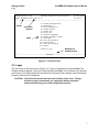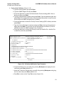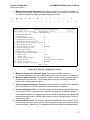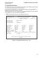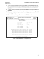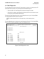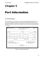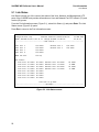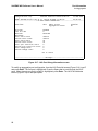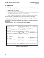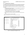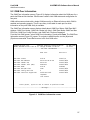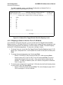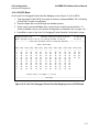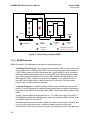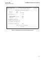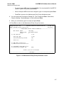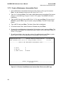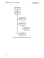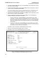
1
EdgeAccess
9145EMP NID Software
Version 3.1
User’s Manual
NOTICE
Canoga Perkins has prepared this user’s manual for use by customers and Canoga
Perkins personnel as a guide for the proper installation, operation and/or maintenance of
Canoga Perkins equipment. The drawings, specifications and information contained in
this document are the property of Canoga Perkins and any unauthorized use or
disclosure of such drawings, specifications and information is prohibited.
Canoga Perkins reserves the right to change or update the contents of this manual and
to change the specifications of its products at any time without prior notification. Every
effort has been made to keep the information in this document current and accurate as of
the date of publication or revision. However, no guarantee is given or implied that the
document is error free or that it is accurate with regard to any specification.
CANOGA PERKINS CORPORATION
20600 Prairie Street
Chatsworth, California 913116008
Business Phone: (818) 7186300
(Monday through Friday 7 a.m. to 5 p.m. Pacific Time)
FAX: (818) 7186312 (24 hrs.)
Web Site: www.canoga.com
Email: [email protected]
Copyright © 2010 Canoga Perkins Corporation
All Rights Reserved
EdgeAccess®
9145EMP NID Software User’s Manual
Product Number 6913805
Rev A 04/2010
EdgeAccess and Canoga Perkins are registered trademarks of Canoga Perkins
Corp.To find Technical Advisories and Product Release Notes, go to the Canoga Perkins
web site at http://www.canoga.com.
9145E NID Software User’s Manual
Contents
Preface ......................................................................................................................... ix
About the Manual ...................................................................................................................ix
How this Manual is Organized ...............................................................................................ix
Contacting Technical Support .................................................................................................x
Documentation Feedback .......................................................................................................x
1 Introduction ............................................................................................................... 1
About the 9145EMP Software ................................................................................................ 1
Management Access ............................................................................................................. 1
Management Security Features ............................................................................................. 1
Three Levels of Security ........................................................................................................ 2
Feature Access Level Configuration ...................................................................................... 2
2 Getting Started .......................................................................................................... 5
Configuring Terminal Management ........................................................................................ 5
Setting Up SNMP Network Management ............................................................................... 6
Management User Interface .................................................................................................. 6
Login ...................................................................................................................................... 7
Main Menu ............................................................................................................................. 8
Supported MIBs ................................................................................................................... 10
The World Leader in Fiber Optic Communications Systems
i
9145E NID Software User’s Manual
3 System Configuration ............................................................................................. 11
System Configuration Menu ................................................................................................. 11
IP/SNMP Agent Configuration ............................................................................................. 12
Management IP Configuration ....................................................................................... 12
Auxiliary IP Configuration ............................................................................................... 14
Host Table ...................................................................................................................... 16
Trap Table ...................................................................................................................... 18
Trap Configuration ............................................................................................................... 24
Security Configuration .......................................................................................................... 26
Password Configuration ................................................................................................. 26
Lockout/Logout Configuration ........................................................................................ 28
Account Configuration .......................................................................................................... 29
Three Levels of Security ................................................................................................ 30
Feature Access Level Configuration ............................................................................... 30
Add or Edit an Account .................................................................................................. 30
Delete an Account .......................................................................................................... 32
System Information .............................................................................................................. 33
RADIUS Client ..................................................................................................................... 33
RADIUS Client Configuration ......................................................................................... 34
SNTP Client Configuration ................................................................................................... 36
SYSLOG Client Configuration .............................................................................................. 38
Hardware Information .......................................................................................................... 39
4 Diagnostics .............................................................................................................. 41
Diagnostic Functions............................................................................................................ 41
Loopback Setup ................................................................................................................... 42
Latency/Jitter Test ................................................................................................................ 43
PING Generation ................................................................................................................. 46
Cable Diagnostics ................................................................................................................. 48
ii
The World Leader in Fiber Optic Communications Systems
9145E NID Software User’s Manual
5 Port Information ...................................................................................................... 49
Port Description ................................................................................................................... 49
Link Status ........................................................................................................................... 50
Port Configuration ................................................................................................................ 51
Hardware Information ..................................................................................................... 52
Functional Configuration ................................................................................................ 53
Port Filters ............................................................................................................................ 54
Network Side Configuration ................................................................................................. 56
Layer 2 Statistics .................................................................................................................. 57
Layer 2 Counter Definitions............................................................................................ 59
Layer 2 Statistics ...................................................................................................... 59
Layer 2 Error Statistics Screen ................................................................................ 59
Layer 2 Frame Type Statistics ................................................................................. 60
RMON Group 1 Statistics ..................................................................................................... 61
Link Aggregation .................................................................................................................. 64
LAG Configuraton .......................................................................................................... 65
Aggregation Group ................................................................................................... 65
LAG Aggregation Ports ............................................................................................ 67
Configuring a Static Link Aggregation ...................................................................... 71
LAG Statistics................................................................................................................. 73
Aggregation Group Statistics ................................................................................... 74
LAG Port Statistics ................................................................................................... 75
6 System Alarms & Logs ........................................................................................... 77
System Alarms...................................................................................................................... 77
System Log .......................................................................................................................... 78
Log Display Filter Configuration .................................................................................... 79
The World Leader in Fiber Optic Communications Systems
iii
9145E NID Software User’s Manual
7 Utilities ..................................................................................................................... 81
Utilities Menu ....................................................................................................................... 81
Set Date and Time ............................................................................................................... 82
Reset Configuration To Default ............................................................................................ 82
Change Password ................................................................................................................ 82
VT100 Baud Rate ................................................................................................................ 83
PING Generation ................................................................................................................. 83
Static ARP Table .................................................................................................................. 84
Dynamic ARP Table ............................................................................................................. 85
License Manager ................................................................................................................. 86
8 Software Upgrade ................................................................................................... 87
Flash Memory ...................................................................................................................... 87
Software Reset .................................................................................................................... 87
Swap Bank & Reset ............................................................................................................. 87
Swap Bank After Download and Reset ................................................................................ 88
Get Software Upgrades with TFTP ...................................................................................... 89
Software Upgrades Using FTP or SFTP .............................................................................. 90
Software Download using FTP ....................................................................................... 90
Software Download using SFTP .................................................................................... 91
9 Link OAM ................................................................................................................. 93
Operation, Administration and Maintenance ........................................................................ 93
OAM Control ........................................................................................................................ 94
OAM Peer Information ......................................................................................................... 97
OAM Statistics ..................................................................................................................... 98
OAM Event Configuration .................................................................................................... 99
iv
The World Leader in Fiber Optic Communications Systems
9145E NID Software User’s Manual
OAM Event Log .................................................................................................................. 100
Event Log Detail Display .............................................................................................. 101
Display Filter Configuration .......................................................................................... 101
10 CoS Configuration .............................................................................................. 103
Class of Service .................................................................................................................. 103
Queues on the 9145EMP ................................................................................................... 103
CoS Support ...................................................................................................................... 105
Enabling or Disabling CoS Support .............................................................................. 105
CoS Queues Configuration ................................................................................................. 106
Tagged Packet Classifier Mapping .............................................................................. 106
Mapping a Queue on the User Port in C-VID Mode109
Untagged Packet Classifier Mapping ........................................................................... 111
IP Precedence Mode ............................................................................................. 112
DSCP Mode ........................................................................................................... 113
AF/EF Mode .......................................................................................................... 114
Queues Configuration on User Ports ........................................................................... 115
Queues Configuration on Network Ports...................................................................... 116
Early Detect Drop Profiles............................................................................................ 118
Queue Statistics ................................................................................................................. 121
11 Service OAM........................................................................................................ 123
Introduction ........................................................................................................................ 123
Service OAM ...................................................................................................................... 123
SOAM Entities.............................................................................................................. 124
Logical Positioning of MEPs and MIPs ........................................................................ 125
SOAM Protocols........................................................................................................... 126
Optional SOAM Configuration...................................................................................... 127
Typical Service OAM Deployment and Applications .................................................... 128
Typical Configuration Sequence .................................................................................. 129
The World Leader in Fiber Optic Communications Systems
v
9145E NID Software User’s Manual
Screen Navigation........................................................................................................ 130
SOAM Configuration .......................................................................................................... 131
Maintenance Domains ....................................................................................................... 136
Display Maintenance Domains..................................................................................... 136
Create a Maintenance Domain .................................................................................... 136
Delete a Maintenance Domain..................................................................................... 138
Modify a Maintenance Domain..................................................................................... 138
Maintenance Associations ................................................................................................. 139
Display Maintenance Associations............................................................................... 139
Create a Maintenance Association .............................................................................. 139
Delete a Maintenance Association............................................................................... 141
Modify a Maintenance Association............................................................................... 141
Maintenance Entity Groups ................................................................................................ 144
Display Maintenance Entity Groups ............................................................................. 144
Create a Maintenance Entity Group............................................................................. 144
Delete a Maintenance Entity Group ............................................................................. 146
Modify a Maintenance Entity Group ............................................................................. 146
Maintenance End Points .................................................................................................... 148
Display Maintenance End Points ................................................................................. 148
Create a Maintenance End Point ................................................................................. 148
Delete a Maintenance End Point.................................................................................. 150
Modify a Maintenance End Point ................................................................................. 150
Interoperability between a Y.1731 MEP and 802.1ag MEPs ....................................... 153
View the Continuity Check Database for a Maintenance End Point ............................ 154
Linktrace Procedures ................................................................................................... 157
Initiating a Linktrace Request ................................................................................. 157
Monitoring a Linktrace Request ............................................................................. 157
Loopback Procedures .................................................................................................. 159
Initiating a Loopback Request ................................................................................ 159
Monitoring a Loopback Request ............................................................................ 163
vi
The World Leader in Fiber Optic Communications Systems
9145E NID Software User’s Manual
Maintenance Intermediate Points ...................................................................................... 163
Display Maintenance Intermediate Points.................................................................... 163
Create a Maintenance Intermediate Point.................................................................... 164
Delete a Maintenance Intermediate Point .................................................................... 165
Modify a Maintenance Intermediate Point.................................................................... 165
Configuration Error List ...................................................................................................... 167
Configure and View SOAM Statistics ................................................................................. 168
MEP Statistics .............................................................................................................. 170
MIP Statistics ............................................................................................................... 171
Statistics Display Confirmation..................................................................................... 173
MEP Statistics ........................................................................................................ 173
MIP Statistics ........................................................................................................ 174
AIS Configuration ............................................................................................................... 175
12 VLAN Multiplexing .............................................................................................. 177
Introduction ......................................................................................................................... 177
VLAN Multiplexing .............................................................................................................. 177
VLAN Multiplexing Records ......................................................................................... 177
User-to-Network Functionality...................................................................................... 178
Network-to-User Functionality...................................................................................... 178
Statistics....................................................................................................................... 178
Screen Navigation........................................................................................................ 179
VLAN Multiplexing Configuration ....................................................................................... 181
Create a VLAN Multiplexing Record ............................................................................ 182
Delete a VLAN Multiplexing Record............................................................................. 183
Modify a VLAN Multiplexing Record............................................................................. 183
Display Statistics for a VLAN Multiplexing Record....................................................... 185
The World Leader in Fiber Optic Communications Systems
vii
9145E NID Software User’s Manual
viii
The World Leader in Fiber Optic Communications Systems
9145EMP NID Software User’s Manual
Preface
About this Manual
This manual provides instructions on the configuration and operation of the 9145EMP Network
Interface Device (NID) Version 3.1 software. The 9145EMP NID can be managed using the EIA232 serial port through a VT100 terminal emulation program, through an Ethernet connection
using Telnet, or by using SNMP.
How this Manual is Organized
This document contains both information and procedures organized in roughly chronological
order. Starting from an introduction to the 9145EMP software, it continues with system
requirements, initial implementation, and continued operation.
The document includes the following chapters:
•
Chapter 1, Introduction, provides basic information about the software and navigation.
•
Chapter 2, Getting Started describes how to set up and get started using the 9145EMP.
•
Chapter 3, System Configuration describes how to configure the 9145EMP management
features.
•
Chapter 4, Diagnostics describes how to configure and perform routine network diagnostics.
•
Chapter 5, Port Information describes the User port, Network port, Multipurpose port, and
the Management UTP port.
•
Chapter 6, System Alarms & Logs describes how to configure System Alarms and System Logs.
•
Chapter 7, Utilities describes system utilities.
•
Chapter 8, Software Upgrade describes how to upgrade the NID software.
•
Chapter 9, Link OAM describes the Operations, Administration, and Maintenance functions, such as remote fault indication and remote loopback control, as specified by the
IEEE 802.3ah standard.
•
Chapter 10, CoS Configuration describes how to enable or disable Class of Service support that includes classification, queuing, scheduling and queue management functions
for the 9145EMP.
ix
9145EMP NID Software User’s Manual
•
Chapter 11, Service OAM describes how to detect, isolate, and report connectivity faults
that span networks comprised of multiple LANs, and monitor the performance of connections.
•
Chapter 12, VLAN Multiplexing describes configuration steps for multiplexing customer
frames to S-VLANs.
Contacting Technical Support
Contact Canoga Perkins technical support (1-800-360-6642), or your 9145EMP support supplier,
for hardware and software support, including product repairs and part ordering. Please have the
following information available:
•
NID model and serial number
•
NID software version
•
Detailed description of the problem and specific questions
•
Details from messages in system log (if available)
•
Description of any troubleshooting steps already performed and results
Documentation Feedback
Because quality is our first concern at Canoga Perkins, we have made every effort to ensure the
accuracy and completeness of this document. However, if you find an error or an omission, or
you think that a topic needs further development, we want to hear from you. Forward your
feedback to: [email protected]. Provide the title and version number and as much detail
as possible about your issue, including the topic heading, page number, and your suggestions for
improvement.
x
Introduction
9145EMP NID Software User’s Manual
Management Access
Chapter 1
Introduction
1.0 About the 9145EMP Software
The Multiport 9145E (9145EMP) is a multiport version of the industry-leading 10/100/1000 9145E
Network Interface Device (NID). The 9145EMP is equipped with four User Ports and two Network
Ports. The User Ports are 10/100/1000 ports supporting dual media, as in the 9145E. The two
Network Ports support 100/1000 optical SFPs only.
The 9145EMP supports Link Aggregation (IEEE 802.3ad) on the Network Ports.
The 9145EMP supports VLAN multiplexing of C-VLANs into S-VLANs. This feature allows customer frames to be multiplexed into S-VLANs through the use of a C-VLAN/S-VLAN Map.
1.1 Management Access
The 9145EMP can be managed through any of several access ports.
VT-100 Terminal The VT-100 terminal is used to manage the NID locally via the EIA-232 serial
port, primarily to perform initial configurations on the NID before it is connected to the network.
Telnet Once the 9145EMP has been connected to your network, it can be accessed using
Telnet. All commands and functions are available using standard Telnet software.
SNMP All commands and functions are also available using an SNMP manager. The 9145EMP
supports SNMP v1/v2c/v3 and many standard MIBs as well as CP proprietary MIBs.
1.2 Management Security Features
The 9145EMP has comprehensive management access security features, including SNMPv3
authorization, RADIUS, password formatting, and user access controls. You can set values and
options within the software that will work with the security protocols on your network. The four
network security protocols listed below are supported. In addition, the 9145EMP provides options
to define strong passwords, independent of the security protocols.
SNMPv3 Provides authentication and encryption of management traffic across a network.
Remote Access Dial In User Security (RADIUS) The RADIUS server maintains user account
information. At login, the 9145EMP queries the server which authenticates the username and
password and sends a message to the 9145EMP to allow the login. The RADIUS server can also
be set up to require additional authentication information before accepting the user. If the
1
9145EMP NID Software User’s Manual
Introduction
Three Levels of Security
username or password is not valid, the RADIUS server sends a message to the 9145EMP to
disallow the login and reject the user.
Secure Shell version 2 (SSH-2) SSH-2 provides authentication and encryption for a secure
remote Telnet connection. SSH can be configured to provide unique User Accounts.
Secure File Transfer Protocol (SFTP) SFTP adds encryption to protect uploaded files during
the file transfer process, such as for a software update.
1.3 Three Levels of Security
Most Service Provider management networks provision certain access levels to technicians,
network administrators, and managers. Offering different access levels to critical applications
allows network administrators to keep closer watch on the entire network.
The 9145EMP allows view-based access to be set up for user interface features and SNMP
access. A capabilities file allows views to be defined in an ASCII file and downloaded to the NID.
A three-level security system on the 9145EMP controls all user interface and SNMPv3 access.
All 9145EMP features require that the user have a certain access level. The logged in user or
SNMPv3 manager’s access level is used to validate and control access to the 9145EMP
features. When accessing a menu item or an SNMP object, the user’s access level is checked
against the access level required for the feature. If the user’s access level is sufficient, then the
access is granted. If the user’s access level is not sufficient, an error message is displayed in the
status area, or an SNMP error is returned.
The three access levels are supervisor, operator, and observer.
•
In the default configuration, the supervisor access level is allowed complete access to all
9145EMP features including configuring the security system.
•
The operator access level is allowed access to the 9145EMP features except those relating to the 9145EMP’s security system. This level can be configurable by the administrator.
•
The observer access level is allowed access to the 9145EMP features that do not modify
the 9145EMP’s configuration. This level can be configurable by the administrator.
1.4 Feature Access Level Configuration
The 9145EMP has a default assignment of access levels. Creating and downloading a text file
called 9145EMP.cap to the 9145EMP can change this assignment. This file contains mappings
between module features and the access level required to access the feature.
As an example the entry that controls access to the Maximum Frame Size setting looks like
maxFrameSize=operator. This entry indicates that to change the Maximum Frame Size, a user’s
account must have “operator” access level or greater.
The default 9145EMP.cap file containing the 9145EMP built-in security rules is provided with the
9145EMP release. To modify the security rules, simply modify the provided 9145EMP.cap file and
download this modified file to the 9145EMP. The 9145EMP.cap file is downloaded to the
9145EMP via the normal FTP/SFTP/TFTP in the same manner as downloading a firmware file to
the 9145EMP. The same file may be downloaded to multiple 9145EMPs to ensure the same
security rules.
2
Introduction
9145EMP NID Software User’s Manual
Feature Access Level Configuration
If the file 9145EMP.cap is not downloaded to the 9145EMP, then the default access level
mappings in the 9145EMP are used. If a feature is not present in the file “9145EMP.cap” that is
downloaded to the 9145EMP, then the default access level mapping in the 9145EMP is used. If
errors are found in this file, these errors are displayed in the System log.
3
9145EMP NID Software User’s Manual
Introduction
Feature Access Level Configuration
4
Getting Started
9145EMP NID Software User’s Manual
Chapter 2
Getting Started
2.0 Configuring Terminal Management
When you use the EIA-232 Serial Port for VT-100 sessions, Canoga Perkins suggests that you
use HyperTerminal or another type of terminal emulation software on a PC.
NOTE: Microsoft Vista does not include HyperTerminal. If your PC uses the Vista
operating system, you will need to install a terminal emulation program.
To set up HyperTerminal on your PC:
1. Select Start > All Programs > Accessories > Communications > HyperTerminal.
2. At the Connection Description dialog, select an icon and enter the name for the
connection. Click OK.
3. At the Connect To dialog, select the Connect Using menu. Select the COM port and
click OK.
4. Select the Port Settings tab from the COM Properties dialog. Make the following
selections:
a. Bits per second: 9600 bps
b. Data bits: 8
c. Parity: None
d. Stop bits: 1
e. Flow control: None
6. Click OK.
7. Go to File > Properties >Settings and change the Emulation setting from Auto detect to
VT100.
8. HyperTerminal connects to the system and the VT100 terminal emulation starts.
5
9145EMP NID Software User’s Manual
Getting Started
Setting Up SNMP Network Management
2.1 Setting Up SNMP Network Management
The 9145EMP communicates with CanogaView or your Network Management Platform either inband, via the Network port, or out of band, via the Management UTP port.
2.1.1 About MIBs
To communicate with the 9145EMP using SNMP, standard Management Information Bases
(MIBs) are required on your Network Management Platform. Refer to “Supported MIBs” on
page 10 for a list of MIBs.
Additionally, Canoga Perkins Private MIBs are needed on the Management Platform to manage
tasks specific to the Canoga Perkins 9145EMP. The Canoga Perkins Private MIBs are available
for download in the Client Support area of the Canoga Perkins web site. Go to www.canoga.com,
then click on Client Support.
NOTE: To log in to the client site or secure site, use the serial number of the 9145EMP to
register.
2.1.2 9145EMP Set-up
Several TCP/IP and SNMP parameters must be configured before you can accessing the
9145EMP from CanogaView or your Management Platform. These parameters include TCP/IP
Address, Authorized Host List and Privileges. These parameters are initialized using a VT-100
Terminal connected to the RS-232 Serial Port. Refer to “System Configuration Menu” on page 11
for details on configuring these parameters.
2.2 Management User Interface
The Management User Interface for the 9145EMP provides a menu driven interface for setup,
monitoring, and diagnostics. You can access the screens directly by connecting to the serial port
of the 9145EMP or using Telnet.
A typical screen (Figure 2-1) includes standard descriptions and reference designations. Use this
and other screens to configure the system, set operational parameters, and verify the system
status. All screens use a common method for navigation.
NOTE: Status screens do not have selectable items.
Use the following methods to navigate screens:
•
When a menu item is highlighted, press the Space bar to view the options for that item.
•
Press Tab to move the highlight to the next column.
•
Press Enter to select the highlighted option for a menu item or to go to the next line.
•
Press Esc once to cancel an action or to return to the previous screen.
To select an item from a screen menu enter the menu item number. For example, you would type
6 and press Enter to select “Utilities” as shown in Figure 2-1.
6
Getting Started
9145EMP NID Software User’s Manual
Login
Canoga Perkins Corp.
Ethernet Network Interface Device
29-JAN-2009
Model 9145EMP-761-0-0 V07.11 F7
10:55:13
-------------------------------------------------------------------------------
MODEL
SOFTWARE
VERSION
MENU
1)
2)
3)
4)
5)
6)
7)
8)
9)
10)
11)
12)
13)
System Configuration
Diagnostics
Port Information
System Alarms
System Log
Utilities
Software Upgrade
Manage Logged In Users
Link OAM
CoS Configuration
Service OAM
VLAN Multiplexing
Logout
Select [1-13]:
MESSAGES &
URGENT STATUS
------------------------------------Messages-----------------------------------
Figure 2-1 Screen Format
2.3 Login
The first screen is the Login screen (Figure 2-2). Type your Username and press Enter. The
Password prompt appears. Type your Password and press Enter. If the Username or Password
are incorrect, you will be returned to the Username Prompt and the message Invalid Username/
Password entered will be displayed.
CAUTION: The default username and password is admin (lower case). Canoga
Perkins strongly recommends you change the default username
and password during your initial configuration session.
7
9145EMP NID Software User’s Manual
Getting Started
Main Menu
Canoga Perkins Corp.
Ethernet Network Interface Device
29-JAN-2009
Model 9145EMP-761-0-0 V07.11 F7
11:14:16
--------------------------------------LOGIN SCREEN-----------------------------
Please Enter Login Username : admin
Please Enter Login Password : *****
------------------------------------Messages-----------------------------------
Figure 2-2 Login screen
When you successfully log in, the Main Menu (Figure 2-3) opens. Use the Main Menu to access
all 9145EMP functions, including setup, diagnostics, and reports.
See the sections “Account Configuration” on page 29 and “Password Configuration” on page 26
for information about configuring you account and changing your password.
CAUTION: If you lose both your Username and Password, return the unit to
Canoga Perkins for Factory Service and reset.
2.4 Main Menu
Following is a brief description of the Main Menu items.
1. System Configuration The System Configuration menu is used to view and set values
for system information and TCP/IP management communications parameters.
2. Diagnostics The Diagnostics menu is used to set up various troubleshooting tests,
including Loopback, Latency/Jitter, PING tests, or Cable Diagnostic.
3. Port Information The Port Information menu is used to ascertain the current conditions
for all ports in the 9145EMP, to set and view the configuration information for specific
ports, check Link Status and Layer 2 Statistics and configure Link Aggregation
functionality.
4. System Alarms The System Alarms screen is used to view current alarm conditions.
5. System Log The System Log screen displays a list of recent traps, alarms, and events.
6. Utilities The Utilities menu is used to set-up and display basic functional information.
8
Getting Started
9145EMP NID Software User’s Manual
Main Menu
Canoga Perkins Corp.
Ethernet Network Interface Device
29-JAN-2009
Model 9145EMP-761-0-0 V07.11 F7
10:55:13
-------------------------------------MAIN MENU--------------------------------1)
2)
3)
4)
5)
6)
7)
8)
9)
10)
11)
12)
13)
System Configuration
Diagnostics
Port Information
System Alarms
System Log
Utilities
Software Upgrade
Manage Logged In Users
Link OAM
CoS Configuration
Service OAM
VLAN Multiplexing
Logout
Select [1-13]:
Figure 2-3 Main Menu
7. Software Upgrade The Software Upgrade screen is used to download and install new
firmware using TFTP, swap firmware banks, and reset the 9145EMP.
8. Manage Logged In Users The Manage Logged In Users screen is used by the
administrator to view current users, and to terminate user sessions when required.
9. Link OAM The OAM menu is used to set, change, and view various link layer
operational, administration and maintenance (OAM) functions.
10. CoS Configuration The Class of Service (CoS) Configuration menu is used to enable or
disable classification support, and to establish priority to queue mapping, set up queue
configuration, create drop profiles, and view queue statistics.
11. Service OAM The Service OAM menu is used to configure Connectivity Fault
Management.
12. VLAN Multiplexing The VLAN Multiplexing menu is used to configure VLAN
Multiplexing.
13. Logout Logout terminates your current session.
9
9145EMP NID Software User’s Manual
Getting Started
Supported MIBs
2.5 Supported MIBs
This section lists all supported MIBs including Standard MIBs and the Canoga Perkins MIBs.
Table 2-1 Standard MIBs
mib-2.my
dot3.oam.my
ifmib.my
ping.my
rmon.my
rmon2.my
hcrmon.my
entitymib.my
cfm.my
Table 2-2 Canoga Perkins MIBs
10
cp9145estatus.my
cplicense.my
cpsyslog.my
cpaccounts.my
cploopback.my
cpsystemlog.my
cpcablediag.my
cpmgmtstatus.my
cptrapconfig.my
cpcos.my
cpping.my
cptraptb.my
cpdot3oam.my
cpportconfig.my
cpvlanloopback.my
cpentitynaming.my
cppowersupply.my
cpvlanmux.my
cpentity.my
cpradius.my
cpfanstatus.my
cpsecurity.my
cphosttb.my
cpsfpstatus.my
cpifmib.my
cpsntp.my
cpipconfig.my
cp_soam_ext.my
cplag.my
cpstatus.my
cplatency.my
cpsysinf.my
System Configuration
9145EMP NID Software User’s Manual
Chapter 3
System Configuration
3.0 System Configuration Menu
The System Configuration menu (Figure 3-1) allows you to access the screens where you can
configure various management, IP, security, and alarm settings. The following section describes
each item on the System Configuration menu.
Canoga Perkins Corp.
Ethernet Network Interface Device
29-JAN-2009
Model 9145EMP-761-0-0 V07.11 F7
Canoga 9145EMP 32 device
11:20:59
----------------------------------SYSTEM CONFIGURATION------------------------1)
2)
3)
4)
5)
6)
7)
8)
9)
IP/SNMP Agent Configuration
Trap Configuration
Security Configuration
Account Configuration
System Information
RADIUS Client Configuration
SNTP Client Configuration
SYSLOG Client Configuration
Hardware Information
Select [1-9]:
------------------------------------Messages-----------------------------------
Figure 3-1 System Configuration Menu
11
9145EMP NID Software User’s Manual
System Configuration
IP/SNMP Agent Configuration
3.1 IP/SNMP Agent Configuration
The IP/SNMP Agent Configuration screen (Figure 3-2) configures the Management IP, Test IP,
and Auxiliary IP settings, and is used to add, edit, or delete Host Table and Trap Table entries.
The Management IP, Test IP, and Auxiliary IP Addresses are used for managing and conducting
testing on a TCP/IP network.
Canoga Perkins Corp.
Ethernet Network Interface Device
29-JAN-2009
Model 9145EMP-761-0-0 V07.11 F7 Canoga 9145EMP 32 device
11:22:37
-------------------------------IP/SNMP AGENT CONFIGURATION---------------------
1)
2)
3)
4)
Management IP Configuration
Auxiliary IP Configuration
Host Table
Trap Table
Select [1-4]
------------------------------------Messages-----------------------------------
Figure 3-2 IP/SNMP Agent Configuration screen
3.1.1 Management IP Configuration
On the IP/SNMP Agent Configuration screen (Figure 3-2), type 1 and press Enter. The
Management IP Configuration screen (Figure 3-3) opens.
Use this screen to configure the Management IP of the 9145EMP, including the subnet mask,
gateway, and management VLAN, and to configure which ports can be used for management
access. See your network administrator for information and help with determining the appropriate
parameters.
1. Manager IP Address Sets the 9145EMP Manager IP Address.
Subnet Mask Sets the 9145EMP Manager IP Subnet Mask.
Default Gateway Sets the IP Address of the Default Gateway.
2. Manager Port Used to select the port(s) to allow Management Communication access.
Options are: Network Port, MGMT UTP Port, and Disabled.
3. Manager VLAN Tagging Enables or disables the use of a Management VLAN. The tags
are 802.1ad compliant. The default setting is Untagged. Options are: Untagged, STagged, C-Tagged, or Double tagged. If you selected “MGMT UTP Port,” only Untagged
or C-Tagged are allowed. If you select "MGMT UTP Only," only untagged and C-Tagged
are allowed.
12
System Configuration
9145EMP NID Software User’s Manual
IP/SNMP Agent Configuration
4. Manager S-VLAN ID If Manager VLAN Tagging is set to S-Tagged or Double Tagged,
you can set the S-VLAN Tag ID between 1 and 4094.
5. Manager C-VLAN ID If Manager VLAN Tagging is C-Tagged or Double Tagged, you can
set the C-VLAN Tag ID between 1 and 4094.
CAUTION: The Manager IP Address, Subnet Mask, and Gateway address can
be changed when locally or remotely connected. When you change
the Management IP Configuration via remote access, you will be
automatically disconnected when the Gateway address is changed.
You will need to reconnect using the updated Manager IP Address,
Subnet Mask, and Gateway address.
Canoga Perkins Corp.
Ethernet Network Interface Device
29-JAN-2009
Model 9145EMP-761-0-0 V07.11 F7 Canoga 9145EMP 32 device
11:43:26
-------------------------------MANAGEMENT IP CONFIGURATION--------------------In-band Manager MAC Address
Manager MAC Address (MGMT UTP)
Manager Port Status
00 40 2A 04 12 D0
00 40 2A 04 12 D2
UP
1)
192.168.092.032
255.255.255.000
192.168.092.001
MGMT UTP Port Only
Untagged
0
0
000.000.000.000
255.255.255.000
No Ports Allowed
Disabled
Disabled
2)
3)
4)
5)
6)
7)
8)
9)
Manager IP Address
Subnet Mask
Default Gateway
Manager Port
Manager VLAN Tagging
Manager C-VLAN ID
Manager S-VLAN ID
Test IP Address
Test Subnet Mask
Test Port
Telnet Security
Reply to Broadcast Ping
Select [1-9]:
Figure 3-3 Management IP Configuration screen
6. Test IP Address Sets the IP Address for optional test features.
Test Subnet Mask Sets the Subnet Mask for optional test features.
7. Test Port Used to select which port(s) allow access to the Test IP address. Options are:
USR Port 1, USR Port 2, USR Port 3, or USR Port 4.
8. Telnet Security Enables or disables checking if the host initiating the Telnet session is
listed in the host table. If Telnet Security is enabled the host must be included as part of
the host table. Default is disabled, which allows access from all hosts.
13
9145EMP NID Software User’s Manual
System Configuration
IP/SNMP Agent Configuration
9. Reply to Broadcast Ping Enables or disables the 9145EMP reply to ICMP packets with
a broadcast IP Host Address in the Manager IP subnet. Broadcast Ping replies are an
ICMP packet and are rate limited to 100pps. Default is disabled.
3.1.2 Auxiliary IP Configuration
On the IP/SNMP Agent Configuration screen (Figure 3-2), type 2 and press Enter. The Auxiliary
IP Configuration screen (Figure 3-4) opens.
The Auxiliary IP is an additional IP address that is provided for testing and connectivity only. It
allows the 9145EMP to be PINGed without allowing Telnet or Management access that could be
disruptive. The Auxiliary IP rate is limited to 500 pings per second. This allows connectivity and
rudimentary performance testing from subscriber/user VLANs without compromising network
security.
To configure the parameters, type the corresponding number and press Enter. Enter data or
press the Space bar to view the configuration choices for the parameters described below.
Separate tagging configuration is necessary for User Side and Network side ports. All ports on
the user side must share the same tagging configuration.
Canoga Perkins Corp.
Ethernet Network Interface Device
29-JAN-2009
Model 9145EMP-761-0-0 V07.11 F7
Canoga 9145EMP 32 device
11:45:26
-------------------------------AUXILIARY IP CONFIGURATION---------------------1)
2)
3)
4)
5)
6)
7)
8)
9)
Auxiliary IP Address
Auxiliary Subnet Mask
Auxiliary Port
Aux VLAN Tagging on Network ports
Aux C-VLAN ID on Network ports
Aux S-VLAN ID on Network ports
Aux VLAN Tagging on User ports
Aux C-VLAN ID on User ports
Allow Any Vlan
Aux IP Rate Limiting
000.000.000.000
255.255.255.000
No Ports Allowed
Untagged
0
0
Untagged
0
Disabled
Enabled
Select [1-9]:
Figure 3-4 Auxiliary IP Configuration screen
1. Auxiliary IP Address Sets the 9145EMP Auxiliary IP Address.
Auxiliary Subnet Mask Sets the 9145EMP Auxiliary IP Subnet Mask.
2. Inband Auxiliary Port Describes the Auxiliary IP address ports. Options are: USR 1,
USR 2, USR 3, USR 4, Network Port, or Disabled.
3. Auxiliary VLAN Tagging on Network ports Describes the tagging mode for the frames
sent and received when the Auxiliary IP address is configured on the Network Port.
Options are: Untagged, S-Tagged, or Double Tagged.
14
System Configuration
9145EMP NID Software User’s Manual
IP/SNMP Agent Configuration
4. Auxiliary C-VLAN ID on Network ports Sets the C-VLAN ID value (between 1 and
4094). Valid if the Auxiliary VLAN Tagging mode on Network ports is set to Double
Tagged.
5. Auxiliary S-VLAN ID on Network Sets the S-VLAN ID value (between 1 and 4094). Valid
if the Auxiliary VLAN Tagging mode on Network ports is set to Double Tagged or STagged. The value defaults to 0 if any of the other type of tagging modes are selected.
6. Auxiliary VLAN Tagging on User ports Describes the tagging mode for the frames sent
and received when the Auxiliary IP address is configured on any of the User Ports.
Options are Untagged or C-Tagged.
7. Auxiliary C-VLAN ID on User ports Sets the C-VLAN ID value (between 1 and 4094) for
the C-Tags on User Ports. Valid if the Auxiliary VLAN Tagging mode on User Ports is set
to C-Tagged.
8. Allow any VLAN If this option is enabled, frames addressed to the Auxiliary IP address
are processed regardless of their VLAN tagging. All responses on such frames are
tagged with the received VLAN ID. Frames initiated by the NID will be still tagged with the
configured encapsulation (Options 3 to 7 above). If this option is disabled, received
frames will only be processed if they have the VLAN ID set on this screen.
9. Auxiliary IP Rate Limiting Specifies whether the maximum limit of 500 frames per
second is enforced for frames received on the Auxiliary IP address.
15
9145EMP NID Software User’s Manual
System Configuration
IP/SNMP Agent Configuration
3.1.3 Host Table
On the IP/SNMP Agent Configuration screen (Figure 3-2), type 3 and press Enter. The Host
Access Table screen (Figure 3-5) opens.
Use this screen to configure the 9145EMP to send and receive SNMP, FTP, and Telnet traffic to
the Managing Host IP address, and access from specific Telnet clients when Telnet security is
enabled. Use the Host Access Table to configure access by each host including access type and
privileges (SNMP, FTP, Telnet).
Canoga Perkins Corp.
Ethernet Network Interface Device
29-JAN-2009
Model 9145EMP-761-0-0 V07.11 F7
Canoga 9145EMP 32 device
11:47:51
--------------------------------HOST ACCESS TABLE-----------------------------Managing Host
Telnet FTP
SNMP
SNMP
V1/V2c Rd
V1/V2c Wr V1/V2c
IP/Mask Bits
Access Access Access Protocol Community
Community Access
172.016.000.000/16 All
All
Write
V1/V2c/V3 public
private
Superv
Select [(A)dd, (D)elete, (E)dit, (M)ore]:
------------------------------------Messages-----------------------------------
Figure 3-5 Host Access Table screen
3.1.3.1 Add or Edit a Managing Host IP
To add a Managing Host IP, from the Host Access Table screen, type A and press Enter. To edit
an existing Managing Host IP select Edit (E). To delete a Managing Host IP select Delete (D).
The Edit Host Access screen (Figure 3-6) opens.
1. Type the Managing Host IP address to add to the Host Access list and press Enter.
2. Type the IP Mask Size (default value 32) and press Enter. To have an entire subnet
access the 9145EMP, enter the mask size for the subnet.
3. To change Telnet Access, type 1 and press Enter. Press the Space bar to select Telnet
and SSH, Telnet Only, SSH Only, or None.
4. To change FTP access, type 2 and press Enter. Press the Space bar to select FTP and
SFTP, FTP Only, SFTP Only, or None. Press Enter to select the parameter.
5. To change SNMP Access parameters, type 3 and press Enter. Press the Space bar to
select Read, Write, or None. Press Enter to select the parameter.
16
System Configuration
9145EMP NID Software User’s Manual
IP/SNMP Agent Configuration
6. To change the SNMP Protocol parameters, type 4 and press Enter. Press the Space bar:
V1/V2c/V3, V1/V2c, or V3 using the Space Bar. Press Enter to select the parameter.
Canoga Perkins Corp.
Ethernet Network Interface Device
29-JAN-2009
Model 9145EMP-761-0-0 V07.11 F7 Canoga 9145EMP 32 device
11:51:16
----------------------------------EDIT HOST ACCESS-----------------------------
1.
2.
3.
4.
5.
6.
7.
Managing Host IP
IP Mask Size
Telnet Access
FTP Access
SNMP Access
SNMP Protocol
V1/V2c Read Community
V1/V2c Write Community
V1/V2c Access Level
:
:
:
:
:
:
:
:
:
Enter Managing Host IP address
------------------------------------Messages-----------------------------------
Figure 3-6 Edit Host Access screen
7. To change V1/V2c Read Community, type 5 and press Enter. Type the desired V1/V2c
Read Community and press Enter.
8. To change the V1/V2c Write Community, type 6 and press Enter. Type the desired V1/
V2c Write Community and press Enter.
9. To change the V1/V2c Access Level, type 7 and press Enter. Press the Space bar to
select Operator, Supervisor, or Observer. Press Enter to select the parameter.
10. Press Esc to return to the Host Access Table screen.
NOTE: SNMP V3 security parameters are configured per user account on the Edit User
Account screen. From the System Configuration screen type 4 and press Enter to
open the Account Configuration screen, then type E to edit an account.
17
9145EMP NID Software User’s Manual
System Configuration
IP/SNMP Agent Configuration
3.1.4 Trap Table
On the IP/SNMP Agent Configuration screen (Figure 3-2), type 4 and press Enter. The Trap
Notification Destination Table screen (Figure 3-7) opens.
The Trap Table screens are used to configure the SNMP Trap Managers.
Canoga Perkins Corp.
Ethernet Network Interface Device
21-MAR-2010
Model 9145EMP-761-0-0 V07.11 F7 Canoga 9145EMP 32 device
11:51:16
---------------------TRAP/NOTIFICATION DESTINATION TABLE----------------------Managing
Trap
Username/
Security
Host
Port Type
Community
Level
Select [(A)dd, (D)elete, (E)dit, (M)ore]:
------------------------------------Messages-----------------------------------
Figure 3-7 Trap/Notification Destination Table screen
3.1.4.1 Adding or Editing a Trap Table
1. To add a Managing Host IP address, from the Trap Notification Destination Table screen
(Figure 3-7), type A and press Enter (to edit, type E and press Enter). The Edit Trap Notification Type screen open (Figure 3-8)
2. Type the Managing Host IP address and press Enter.1
3. Type the Trap/Notification Port and press Enter.
The default value is 162 for regular SNMP managers (163 for CanogaView). Any port
numbers from 1 to 65535 can be used to receive traps. Check with your IT manager to
ensure the port setting is correct.
18
System Configuration
9145EMP NID Software User’s Manual
IP/SNMP Agent Configuration
NOTE: Each Notification Type has a different configuration procedure. Follow the specific
procedure for the Notification Type selected.
Canoga Perkins Corp.
Ethernet Network Interface Device
29-JAN-2009
Model 9145EMP-761-0-0 V07.11 F7
Canoga 9145EMP 32 device
11:53:23
----------------------------------EDIT TRAP/NOTIFICATION TYPE-----------------IP Address
Trap/Notification Port
Notification Type
:
:
:
Enter Managing Host IP address
------------------------------------Messages-----------------------------------
Figure 3-8 Edit Trap/Notification Type screen
Canoga Perkins Corp.
Ethernet Network Interface Device
29-JAN-2009
Model 9145EMP-761-0-0 V07.11 F7
Canoga 9145EMP 32 device
11:53:23
---------------------TRAP/NOTIFICATION DESTINATION TABLE----------------------Managing
Trap
Username/
Security
Host
Port Type
Community
Level
172.002.015.032
172.002.145.011
172.016.002.034
172.016.150.014
162
162
162
162
V2c-Inform
V3-Trap
V3-Inform
V1-Trap
Private
admin
admin
public
N/A
Auth/Priv
Auth/Priv
N/A
Select [(A)dd, (D)elete, (E)dit, (M)ore]:
------------------------------------Messages-----------------------------------
Figure 3-9 Trap/Notification Destination Table screen
19
9145EMP NID Software User’s Manual
System Configuration
IP/SNMP Agent Configuration
Canoga Perkins Corp.
Ethernet Network Interface Device
29-JAN-2009
Model 9145EMP-761-0-0 V07.11 F7 Canoga 9145EMP 32 device
15:52:50
---------------------TRAP/NOTIFICATION DESTINATION TABLE----------------------Managing
Host
172.002.015.032
172.002.145.011
172.016.002.034
172.016.150.014
Port
Trap
Type
Username/
Community
Security
Level
162
162
162
162
V2c-Inform
V3-Trap
V3-Inform
V1-Trap
Private
admin
admin
public
N/A
Auth/Priv
Auth/Priv
N/A
SPACE BAR to move cursor, CR to edit entry, ESC to exit:
------------------------------------Messages-----------------------------------
Figure 3-10 Edit Trap/Notification Type screen
4. Select the Notification Type for this SNMP host. Selections are: V1-Trap, V2c-Trap, V2cInform, V3-Trap, and V3-Inform.
•
If you select V1-Trap or V2c-Trap (Figure 3-11):
a. Enter the Community Name and press Enter.
b. Press Esc to return to the Trap Table screen (Figure 3-9).
20
System Configuration
9145EMP NID Software User’s Manual
IP/SNMP Agent Configuration
Canoga Perkins Corp.
Ethernet Network Interface Device
29-JAN-2009
Model 9145EMP-761-0-0 V07.11 F7
Canoga 9145EMP 32 device
15:52:50
----------------------------------EDIT TRAP/NOTIFICATION TYPE-----------------IP Address
Trap/Notification Port
Notification Type
1. Community Name
: 172.016.150.014
: 162
: V1-Trap
: public
Select [1]:
------------------------------------Messages-----------------------------------
Figure 3-11 V1-Trap or V2c-Trap Notification Type Parameter
•
If you select V2c-Inform (Figure 3-12):
a. Enter the Community Name.
b. Accept or revise the Retries parameter (default is 3).
c. Accept or revise the Timeout in Seconds parameter (default is 5).
d. Press Enter and then press Esc to return to the Trap Table screen (Figure 3-9).
•
If you select V3-Trap (Figure 3-13):
a. Press the Space bar to select the Security Name and press Enter.
b. Press the Space bar to select the Security Level (No Auth/No Priv, Auth/No Priv,
or Auth/Priv) and press Enter.
c. Press Esc to return to the Trap Table screen (Figure 3-9).
21
9145EMP NID Software User’s Manual
System Configuration
IP/SNMP Agent Configuration
Canoga Perkins Corp.
Ethernet Network Interface Device
29-JAN-2009
Model 9145EMP-761-0-0 V07.11 F7 Canoga 9145EMP 32 device
15:52:50
--------------------------------EDIT TRAP/NOTIFICATION TYPE-------------------IP Address
: 172.002.015.032
Trap/Notification Port : 162
Notification Type
: V2c-Inform
1. Community Name
2. Retries
3. Timeout in Seconds
: Private
: 5
: 30
Select [1-3]:
------------------------------------Messages-----------------------------------
Figure 3-12 V2c-Inform Notification Type Parameter
Canoga Perkins Corp.
Ethernet Network Interface Device
29-JAN-2009
Model 9145EMP-761-0-0 V07.11 F7 Canoga 9145EMP 32 device
15:52:50
----------------------------------EDIT TRAP/NOTIFICATION TYPE------------------
IP Address
Trap/Notification Port
Notification Type
1. Security Name
2. Security Level
: 172.002.145.011
: 162
: V3-Trap
: admin
: Auth/Priv
Select [1-2]:
-----------------------------------Messages-----------------------------------
Figure 3-13 V3-Trap Notification Type Parameter
22
System Configuration
9145EMP NID Software User’s Manual
IP/SNMP Agent Configuration
4. If you select V3-Inform (Figure 3-15):
a. Type the Security Name and press Enter.
b. Type the SNMP Engine ID and press Enter.
c. Press the Space bar to select the Authentication Protocol setting (MD5, SHA, or
None) and then press Enter.
d. Type the Authentication Password and press Enter. Type the password again and
press Enter. The Authentication Key will automatically be entered. (It can be modified to match the SNMP manager's key if needed.)
e. Press the Space bar to select the Privacy Protocol settings (DES or None) and then
press Enter
f. Type the Privacy Password, if required, and press Enter, then type the password
again and press Enter. The Privacy Key will automatically be entered. (It can be
modified to match the SNMP manager's key if needed.)
g. Press the Space bar to select the Security Levels (No Auth/No Priv, Auth/No Priv,
or Auth/Priv) and then press Enter.
Canoga Perkins Corp.
Ethernet Network Interface Device
29-JAN-2009
Model 9145EMP-761-0-0 V07.11 F7 Canoga 9145EMP 32 device
15:52:50
----------------------------------EDIT TRAP/NOTIFICATION TYPE-----------------IP Address
: 172.016.002.034
Trap/Notification Port : 162
Notification Type
: V3-Inform
1. Security Name
: admin
2. Engine ID
: 646EDB8608522E7733B4E38D28ABC8A130D8D041
3. Authentication Protocol : SHA
4. Authentication Password : ***************
5. Authentication Key
: FA9F82E713BAF2D2AC93DE8237BF5D1D5129261B
6. Privacy Protocol
: DES
7. Privacy Password
: ***************
8. Privacy Key
: 8FDA9A99556396C7B32BA38EF58F6DE4
9. Security Level
: Auth/Priv
10. Retries
: 3
11. Timeout in Seconds
: 30
Select [1-11]:
-----------------------------------Messages-----------------------------------
Figure 3-14 V3-Inform Notification Type Parameter
h. Accept the Retries entry or modify it by pressing Backspace and typing the new
value and press Enter (default is 3).
i. Accept the Timeout in Seconds entry or modify it by pressing Backspace and typing
the new value and press Enter (default is 5).
j. Press Esc to return to the Trap Table screen (Figure 3-8).
23
9145EMP NID Software User’s Manual
System Configuration
Trap Configuration
3.1.4.2 Delete a Trap Table Entry
1. To delete a Managing Host IP address, from the Trap Notification Destination Table
screen (Figure 3-9), type D and press Enter.
2. Press the Space bar to select a Host IP address. To delete, press Enter. You will be
prompted to confirm the deletion.
3. Press Esc to return to the IPSN MP Agent Configuration screen (Figure 3-2).
3.2 Trap Configuration
Trap configuration defines how various alarms events are handled. Traps can be configured to be
logged, sent to the SNMP managers in the Trap Notification/Destination Table, or both logged
and sent for each event. Traps can also be set to Disabled.
Trap Config Item
Traps Affected
Master Trap Control
All
User Port Link Traps
linkUp (User Port)
ifmib.my
linkDown (User Port)
ifmib.my
linkUp (Network Port)
ifmib.my
linkDown (Network Port)
ifmib.my
cp9145EPortRemoteFaultReceived
cp9145EStatus.my
cp9145EPortSendingRemoteFault
cp9145EStatus.my
cp9145EPortRemoteFaultCleared
cp9145EStatus.my
Cold Start Traps
coldStart
v2-mib.my
Authentication Traps
cpAuthenticationFailure
cpMgmtStatus.my
Diagnostic Traps
cpPortLoopbackOn
cpLoopback.my
cpPortLoopbackOff
cpLoopback.my
entConfigChange
EntityMib.my
Network Port Link Traps
Remote Fault Traps
Entity Configuration Traps
Fan/Power/Temperature Traps cpMainBoardVoltageLevelsOK
24
MIB Location
cpStatus.my
cpMainBoardVoltageLevelsOutOfRange
cpStatus.my
cpDyingGasp
cpPowerSupply.my
cpPowerSupplyFailed
cpPowerSupply.my
cpPowerSupplyOverHighLimit
cpPowerSupply.my
cpPowerSupplyUnderLowLimit
cpPowerSupply.my
cpPowerSupplyOK
cpPowerSupply.my
cpFanShutDownDueToLowTemperature
cpFanStatus.my
cpFanOK
cpFanStatus.my
System Configuration
9145EMP NID Software User’s Manual
Trap Configuration
cpFanSlow
cpFanStatus.my
cpFanFailed
cpFanStatus.my
cpTemperatureOverHighThresholdAlarm
cpStatus.my
cpTemperatureHighThresholdAlarmCleared
cpStatus.my
cpTemperatureWarningApproachingHighThreshold cpStatus.my
SFP Traps
Service OAM Traps
cpTemperatureHighThresholdWarningCleared
cpStatus.my
cpTemperatureAlarmUnderLowThreshold
cpStatus.my
cpTemperatureLowThresholdAlarmCleared
cpStatus.my
cpTemperatureWarningApproachingLowThreshold
cpStatus.my
cpTemperatureLowThresholdWarningCleared
cpStatus.my
cpSfpRemoved
cpSfpStatus.my
cpSfpInsertedInvalid
cpSfpStatus.my
cpSfpInsertedValid
cpSfpStatus.my
cpSfpTxOk
cpSfpStatus.my
cpSfpTxWarning
cpSfpStatus.my
cpSfpTxFailure
cpSfpStatus.my
cpSoamXConnCcm
cp_soam_ext.my
cpSoamErrorCcm
cpSoamRMepCcm
cpSoamMacStatus
cpSoamRDIDetect
cpSoamAISDetect
The System Log contains the log of all enabled Trap events.
1. To configure Traps, select Trap Configuration (2) from the System Configuration menu.
The Trap Configuration screen (Figure 3-15) opens.
2. Select the number of the trap group to change and press Enter. Press the Space bar to
select Log Only, Send Only, Both Log And Send, or Disabled.
The Master Trap Control setting will override all other trap settings. For example, if the
Master Trap Control is set to Log Only, rather than set to Both Log And Send (as shown),
all the other traps will only log alarm events, regardless of the individual trap settings. If
the Master Trap Control is set to Log And Send, the individual traps will perform
according to their individual settings. Setting the Master Trap Control setting to Disabled
will disable all traps.
3. Press Enter to close the editing function and then press Esc to return to the System
Configuration screen.
25
9145EMP NID Software User’s Manual
System Configuration
Security Configuration
NOTE: The setting of the Master Trap Control overrides all other trap settings.
Canoga Perkins Corp.
Ethernet Network Interface Device
29-JAN-2009
Model 9145EMP-761-0-0 V07.11 F7 Canoga 9145EMP 32 device
15:52:50
-----------------------------------TRAP CONFIGURATION-------------------------1) Master Trap Control
Log Only
2)
3)
4)
5)
User Port Link Traps
Network Port Link Traps
Remote Fault Traps
Link Loss Forwarding Traps
Both
Both
Both
Both
Log
Log
Log
Log
And
And
And
And
Send
Send
Send
Send
Cold Start Traps
Authentication Traps
Diagnostic Traps
Entity Configuration Traps
Fan/Power/Temperature Traps
Both
Both
Both
Both
Both
Both
Log
Log
Log
Log
Log
Log
And
And
And
And
And
And
Send
Send
Send
Send
Send
Send
6)
7)
8)
9)
10)
12) SOAM Traps
Both Log And Send
Select [1-12]:
Figure 3-15 Trap Configuration screen
3.3 Security Configuration
The 9145EMP can be configured for Strong passwords. Use the Security Configuration screen to
set or change the Password Configuration and the Lockout/Logout Configuration.
From the System Configuration screen, select Security Configuration (3). The Security
Configuration screen (Figure 3-16) opens.
3.3.1 Password Configuration
Select the Password Configuration item to change by typing the corresponding number. Press
Enter to close the editing function and then press Esc to return to the System Configuration
screen. The 9145EMP permits strong passwords as follows:
1. Minimum Length The minimum number of alpha-numeric characters of a password.
Enter a value between 0 and 15. A setting of 0 will allow you to log in without a password.
2. Minimum Alpha Characters The minimum number of alpha characters a password must
contain. Valid alpha characters are a-z (lower case) and A-Z (capitalized). Enter a value
between 0 and 15.
3. Minimum Numeric Characters The minimum number of numeric characters a password
must contain. Valid numeric characters are 0-9. Enter a value between 0 and 15.
26
System Configuration
9145EMP NID Software User’s Manual
Security Configuration
4. Minimum Punctuation Characters The minimum number of punctuation characters a
password must contain. Valid punctuation characters are any non-space, non-alpha, and
non-numeric characters. Valid punctuation characters include:
!
@
#
$
%
^
&
*
(
)
_
+
-
,
<
.
=
~
‘
;
:
‘
“
[
{
]
}
\
|
>
/
?
Canoga Perkins Corp.
Ethernet Network Interface Device
29-JAN-2009
Model 9145EMP-761-0-0 V07.11 F7
Canoga 9145EMP 32 device
15:52:50
----------------------------SECURITY CONFIGURATION--------------------------------------PASSWORD CONFIGURATION
1. Minimum Length
: 6
2. Minimum Alpha Characters
: 0
3. Minimum Numeric Characters
: 0
4. Minimum Punctuation Characters
: 0
5. Maximum Consecutive Character Types : 0
6. Maximum Same Character
: 0
7. Allow username in password
: Enabled
8. Password Expiration Time
: 0
9. Password Reuse Count
: 0
LOCKOUT/LOGOUT CONFIGURATION
10. Lockout After Failed Attempts
: 0
11. Lockout Type
: Hard
Lockout time
: 0
12. Display Lockout Message
: Disabled
13. Lockout Message
: Account has been locked out
14. Lockout Craft Port
: Disabled
15. Inactivity Logout time (mins)
: 0
Select [1-15]:
Figure 3-16 Security Configuration screen
5. Maximum Consecutive Character Types The number of alpha, numeric, or
punctuation characters that can be used consecutively. Enter a value from 1 through 15.
6. Maximum Same Character The maximum number of times that any character may be
repeated within the password. This includes alpha, numeric or punctuation character
types. Enter a value between 0 and 15.
7. Allow Username In Password Determines if the user’s account name can be within any
part of the password. Press the Space bar to select Enabled or Disabled.
8. Password Expiration Time The number of days until the password expires and a new
one is required. Enter a value between 1 and 365. A setting of 0 disables this feature.
If the password expires, the Supervisor will have to reset the password. If the Supervisor
password has expired the 9145EMP NID will have to sent to Canoga Perkins Technical
Support to be reset.
9. Password Reuse Count The number of password expirations a user must wait until a
password can be reused. When set to 0, the user can reuse their current password with
no count limitation. When set to 1, a password can be reused after one password reset.
27
9145EMP NID Software User’s Manual
System Configuration
Security Configuration
3.3.2 Lockout/Logout Configuration
Select the Lockout/Logout Configuration item you want to change by typing the corresponding
number. Press Enter to close the editing function and then press Esc to return to the System
Configuration screen.
10. Lockout After Failed Attempts The number of attempts a user may make before the
account becomes disabled. The Lockout Type field controls the lockout behaviors. Enter
a value between 1 and 15. A setting of 0 will disable this feature.
11. Lockout Type The options are Hard or Timed. Timed requires the user to wait a
specified number of minutes before a retry. Hard requires the System Administrator to
unlock the account. Press the Space bar to select Timed or Hard.
Lockout Time The number of minutes that a user must wait before a retry. Enter a value
between 0 and 30.
12. Display Lockout Message Specifies if a message will be displayed when an account
has been locked. Refer to the Lockout Message in option 13. Press the Space bar to
select Enabled or Disabled.
13. Lockout Message The text to be displayed if option 12 is Enabled. The message should
be customized to list the person to contact in case an account is disabled. Enter a text
message of up to 30 characters.
14. Lockout Craft Port Specifies whether the RS-232 serial port interface on the device
should be locked to prevent using the serial interface to access the system. Press the
Space bar to select Enabled or Disabled.
15. Inactivity Logout Time The number of minutes of inactivity before a user is
automatically logged out. Enter a value between 1 and 30. A setting of 0 will disable this
feature.
28
System Configuration
9145EMP NID Software User’s Manual
Account Configuration
3.4 Account Configuration
Use the Account Configuration screen to add new accounts, edit existing accounts, or delete
accounts. There must be at least one Supervisor account. The 9145EMP NID allows up to 24
accounts. Four telnet sessions may take place at the same time. Only one FTP session may take
place at any time.
NOTE: Any action that affects the network configuration of the 9145EMP (that is,
resetting the IP address) will disconnect all telnet sessions.
From the System Configuration menu, select Account Configuration (4). The Account
Configuration screen (Figure 3-17) opens.
Canoga Perkins Corp.
Ethernet Network Interface Device
29-JAN-2009
Model 9145EMP-761-0-0 V07.11 F7 Canoga 9145EMP 32 device
15:52:50
------------------------------ACCOUNT CONFIGURATION---------------------------Account
Access
Access
Locked
Username
State
From
Level
Description
Out
admin
Obs
Ope
Enabled
Enabled
Disabled
UI/SNMPv3
UI/SNMPv3
UI/SNMPv3
Supervisor
Observer
Operator
Default Account
New Account
new account
No
No
No
Select [(A)dd, (D)elete, (E)dit, (M)ore]:
-----------------------------------Messages-----------------------------------
Figure 3-17 Account Configuration screen
1. Username The name of the new account you wish to add to the user list.
2. Account State Whether the account is enabled or disabled.
3. Access From Determines from where the user can access this account.
4. Access Level The security level required to access this account.
5. Description The account type.
6. Locked Out Whether the Supervisor has locked the user out of the system.
29
9145EMP NID Software User’s Manual
System Configuration
Account Configuration
3.4.1 Three Levels of Security
A three-level security system on the 9145EMP controls all user interface and SNMPv3 access.
Most Service Provider management networks provision certain access levels to technicians,
network administrators, and managers. Offering different access levels to critical applications
allows network administrators to keep closer watch on the entire network.
All 9145EMP features require a certain access level for access. The logged in user or SNMPv3
manager’s access level is used to validate and control access to the 9145EMP features. When
accessing a menu item or an SNMP object the user’s access level is checked against the access
level required for the feature. If the user’s access level is sufficient, then the access is granted. If
the user’s access level is not sufficient, an error message is displayed in the status area or an
SNMP error is returned.
The three access levels are supervisor, operator, and observer.
In the default configuration, the supervisor access level is allowed complete access to all
9145EMP features including configuring the security system. The operator access level is
allowed access to the 9145EMP features except those relating to the 9145EMP’s security
system. This level can be configurable by the administrator.
The observer access level is allowed access to the 9145EMP features that do not modify the
9145EMP’s configuration. This level can be configurable by the administrator.
3.4.2 Feature Access Level Configuration
The assignment of access levels has a default configuration built into the 9145EMP. Creating and
downloading a text file called 9145e.cap to the 9145EMP can change this assignment, however.
This file contains mappings between module features and the access level required to access
the feature. For example, the entry that controls access to the Maximum Frame Size setting
looks like the following:
maxFrameSize=operator
This entry indicates that to change the Maximum Frame Size, a user’s account must have
operator access level or greater.
The 9145e.cap file is downloaded to the 9145EMP via the normal FTP/SFTP/TFTP in the same
manner as downloading a firmware file to the 9145EMP. The same file may be downloaded to
multiple 9145EMP's to ensure that each is following the same security rules.
3.4.3 Add or Edit an Account
To add an account, from the Account Configuration screen (Figure 3-17), type A and press Enter.
The Edit User Account screen (Figure 3-18) opens with all fields empty. When you have entered
the account information, press Esc to return to the Account Configuration screen.
To edit an account, type E and press the Space bar to select an account. The Edit User Account
screen (Figure 3-18) opens.
30
System Configuration
9145EMP NID Software User’s Manual
Account Configuration
Canoga Perkins Corp.
Ethernet Network Interface Device
29-JAN-2009
Model 9145EMP-761-0-0 V07.11 F7 Canoga 9145EMP 32 device
15:52:50
----------------------------------EDIT USER ACCOUNT--------------------------------Username
: Obs
1. Account State
: Enabled
2. Access From
: UI/SNMPv3
3. Access Level
: Observer
4. Description
: New Account
5. UI Password
: ***************
6. UI Password Expires
: No
UI Password Expires in (days) : 0
7. Allow UI Lockout Of User
: Yes
8. Allow UI Logout Of User
: Yes
9. UI Login Locked State
: Unlocked
10.SNMPv3 Authentication Protocol : None
11.SNMPv3 Authentication Password : N/A
SNMPv3 Authentication Key
: N/A
12.SNMPv3 Privacy Protocol
: None
13.SNMPv3 Privacy Password
: N/A
SNMPv3 Privacy Key
: N/A
Select [1-13]:
Figure 3-18 Edit User Account screen
Username The name of the new account you wish to add to the user list. Enter a name of up to
10 characters.
1. Account State Specifies whether the account is active. Press the Space bar to select
Enabled or Disabled.
2. Access From Determines from where the user can access this account. Press the
Space bar to select between UI, SNMPv3, and UI/SNMPv3.
NOTE: SNMP only cannot FTP.
3. Access Level Specifies the security level granted when you log in with this account.
Press the Space bar to select Observer, Operator, or Supervisor.
4. Description Term used to describe the account type. Enter descriptive text up to 17
characters.
5. UI Password A password is only required if Access From is set to UI or UI/SNMPv3.
Type the desired password and press Enter. Reenter the password. Passwords are
limited to 15 characters.
6. UI Password Expires Determines whether the password will expire and required to be
changed. Press the Space bar to select Yes or No.
Password Expires in (days) Establishes the number of days each password can be
used before a new password is required. Enter a number between 1 and 365. A setting of
0 will require a new password each time the account is opened.
7. Allow UI Lockout Of User Gives Supervisors the ability to lock users out of the system.
Press the Space bar to select Yes or No.
31
9145EMP NID Software User’s Manual
System Configuration
Account Configuration
8. Allow UI Logout Of User Gives Supervisors the ability to log users off the system. Press
the Space bar to select Yes or No.
9. UI Login Locked State Determines the current state of the UI Login. Press the Space
bar to select Locked or Unlocked.
10. SNMPv3 Authentication Protocol Sets the authentication protocol for SNMPv3 access.
Press the Space bar to select None, MD5, or SHA.
11. SNMPv3 Authentication Password Used to enter the SNMPv3 authentication
password. This password is not stored. It is used to generate the SNMPv3 authentication
key. Type the desired password and press Enter. Reenter the password. The password is
required to be between 8 and 15 characters. This field will be passed over if the SNMPv3
authentication protocol is set to None.
SNMPv3 Authentication Key Displays the computed SNMPv3 authentication key. This
is a field that is shared with an SNMPv3 management application to allow authenticated
protocol exchanges.
12. SNMPv3 Privacy Protocol The privacy protocol used for SNMPv3 access. Press the
Space bar to select None or DES.
13. SNMPv3 Privacy Password Used to enter the SNMPv3 privacy password. This
password is not stored. It is used to generate the SNMPv3 privacy key. Type the desired
password and press Enter. Reenter the password. The password is required to be
between 8 and 15 characters. This field will be passed over if the SNMPv3 Privacy
Protocol is set to None.
SNMPv3 Privacy Key Displays the computed SNMPv3 privacy key. This is a field that
must be shared with an SNMPv3 management application to allow private SNMPv3
protocol exchanges.
3.4.4 Delete an Account
NOTE: An account cannot be deleted while the user is logged in. In addition, you cannot
delete the last supervisor account.
Before attempting to delete an account make sure the user is logged out. Use the following
procedure to delete an account.
1. To delete an account, from the Account Configuration screen (Figure 3-17), type D and
press Enter. The first User Account will be highlighted.
2. Press the Space bar to scroll through the user names to select the account. Press Enter
to delete the highlighted account.
3. When deletions are completed, press Esc to return to the System Configuration menu.
32
System Configuration
9145EMP NID Software User’s Manual
System Information
3.5 System Information
The System Information screen is used to add or edit administrative and circuit information, such
as the name of the 9145EMP, contact, location, customer, circuit, equipment codes and Common
Language Equipment Identification (CLEI) information.
System Name, Contact, and Location are the same as the MIB-II variables sysName,
sysLocation, sysContact.
1. From the System Configuration menu, select System Information (5) and press Enter.
The System Information screen (Figure 3-19) opens.
2. Type the number of the parameter to enter information about, then press Enter.
3. Type new information or edit existing information and press Enter.
4. To return to the Main Menu, press Esc. Press Esc again to return to the System
Configuration menu.
Canoga Perkins Corp.
Ethernet Network Interface Device
29-JAN-2009
Model 9145EMP-761-0-0 V07.11 F7 Canoga 9145EMP 32 device
15:52:50
------------------------------SYSTEM INFORMATION------------------------------1 System Name
: Canoga 9145EMP 32 device
2. Contact
: Contact
3. Location
: Canada
4. Customer
: Afore Solutions
5. Information
: Information1
: Information2
6. Circuits
: Circuits1
: Circuits2
7. Service Code
: 1234567890
8. Date-in-Service
: 03/04/2010
9. Date-Out-of-Service : 03/01/2010
10. Equipment Type
: Test Equip
11. Equipment Code
: 1234567890
12. Vendor
: Canoga Perkins
13. CLEI
: 1234567890
14. Mfg Date
: 01/01/2010
Select [1-14]:
------------------------------------Messages-----------------------------------
Figure 3-19 System Information screen
1. System Name The system name can be up to 25 characters long. It is displayed in the
header under Ethernet Network Interface Device. If you are running multiple telnet sessions, you will be able to identify the NID you are viewing.
2. Contact Maximum of 25 characters.
3. Location Maximum of 25 characters.
33
9145EMP NID Software User’s Manual
System Configuration
RADIUS Client
4. Customer Maximum of 25 characters.
5. Information Two lines, maximum of 40 characters each.
6. Circuits Two lines, maximum of 25 characters each.
7. Service Code Maximum of 10 characters.
8. Date-in-Service The date when the 9145EMP was placed into service.
9. Date-Out-of-Service The date when the 9145EMP was last taken out of service.
10. Equipment Type Maximum of 10 characters.
11. Equipment Code Maximum of 10 characters.
12. Vendor Maximum of 25 characters.
13. CLEI Common Language Equipment Identification (CLEI) up to 10 characters.
14. Mfg Date An editable date field in the form [mm/dd/yyyy].
3.6 RADIUS Client
RADIUS (Remote Authentication Dial-In User Service) software support is provided for User
Authentication.
RADIUS provides the ability to have user interface accounts to be maintained and authenticated
by a RADIUS server. The RADIUS server also maintains user account information:
•
AccessFrom Where the account can be used.
•
AccessLevel The security access level for the user.
•
Description The account description.
•
LogoutUser Whether the user can be forcefully logged out.
When a user enters a username and password and RADIUS has been configured, the username
and password is sent to the RADIUS server and is validated there. If valid, then the RADIUS
server sends an accept message along with the above account information and the 9145EMP
RADIUS client allows the user in with this configuration.
The RADIUS server may send a reject message in which case the user is not logged in. The
RADIUS server may also send a challenge message if it has been configured to do so in which
case the user is prompted for additional authentication information at which time the RADIUS
server will then send an accept or reject message.
3.6.1 RADIUS client configuration
Up to two RADIUS servers can be configured. The RADIUS server that is consulted is
determined by the server priority. The server with the lowest priority number is consulted first. If it
does not respond, then the other RADIUS server is consulted (if configured). If both servers are
configured with the same priority then a round-robin access is used; first one RADIUS server will
be consulted and the next request will be sent to the other RADIUS server first. The server
priorities are relative. That is, you could configure one server with priority 10 and the other with
20. The values of the numbers do not matter, just the relative values of the numbers (in this case
10 being less than 20). This is done to allow you to easily change the server priorities without
having to edit both entries. If you had configured the servers with 10 and 20, you could make the
34
System Configuration
9145EMP NID Software User’s Manual
RADIUS Client
server with 20 have higher priority simply by changing its priority to 5; no need to change the one
with 10. The RADIUS Client Configuration Client screen is shown in Figure 3-20.
1. RADIUS Client Mode Options: RADIUS then Local, Local then RADIUS, or None
2. RADIUS then Local When a user tries to log in, the username and password is passed to
the configured Primary RADIUS Server first for authentication. If there is no connectivity
to the Primary RADIUS Server, the RADIUS Client attempts to authenticate the login
request on the Secondary RADIUS Server. If there is no connectivity to the Secondary
RADIUS Server, the 9145EMP can then use the local database.
3. Local then RADIUS says that when a user tries to log in, the local user accounts
database is consulted to try to authenticate the user. If the user cannot be authenticated
by the local accounts database, then the RADIUS Server is consulted to authenticate the
user.
4. None says that the RADIUS server is never used and all user access is authenticated by
the local user accounts database.
5. RADIUS Server IP Address The IP address of the RADIUS server. If 0.0.0.0 then this
server configuration will not be used.
6. RADIUS Server Shared Secret 16-character secret shared by the RADIUS server and
the RADIUS client to encrypt sensitive RADIUS traffic on the wire. The value entered
here must match what is configured into the RADIUS server.
7. RADIUS Server Retries The number of attempts to authenticate a user using this
RADIUS server before giving up or using the alternate RADIUS server if configured. 0 10
8. RADIUS Server Timeout The time in seconds (1-30) before assuming that the RADIUS
server did not reply and retrying a request if so configured.
9. RADIUS Server Priority The RADIUS server priority in relation to the alternate RADIUS
server if configured. The server with the lower priority will be consulted first to
authenticate a user. Servers with the same priority operate in a round-robin fashion
alternating requests to each server.
35
9145EMP NID Software User’s Manual
System Configuration
SNTP Client Configuration
Canoga Perkins Corp.
Ethernet Network Interface Device
29-JAN-2009
Model 9145EMP-761-0-0 V07.11 F7 Canoga 9145EMP 32 device
15:52:50
-------------------------RADIUS CLIENT CONFIGURATION--------------------------1. RADIUS Client
2. RADIUS Server
RADIUS Server
RADIUS Server
RADIUS Server
RADIUS Server
3. RADIUS Server
RADIUS Server
RADIUS Server
RADIUS Server
RADIUS Server
Mode
:
IP Address
:
Shared Secret:
Retries
:
Timeout
:
Priority
:
IP Address
:
Shared Secret:
Retries
:
Timeout
:
Priority
:
None
0.0.0.0
3
5
1
0.0.0.0
3
5
1
Select [1-3]:
-----------------------------------Messages-----------------------------------
Figure 3-20 RADIUS Client Configuration screen
3.7 SNTP Client Configuration
Use the SNTP Client Configuration screen to configure the 9145EMP to use a primary and
secondary SNTP Server to automatically set the date and time. An accurate date and time in the
9145EMP assures accuracy for events listed in the System Log and for traps and alarms sent to
the system administrator. You can choose either of two methods for setting the date and time,
depending on your access to an external network and your need for accuracy.
•
For accuracy within a large network, you can set up the 9145EMP to synchronize the
system date and time to an SNTP server.
•
The time and date can be set manually. See “Set Date and Time” on page 82 for more
information.
To configure SNTP, select SNTP Client Configuration (7) from the System Configuration menu
and press Enter. The Simple Network Time Protocol (SNTP) Client Configuration screen (Figure
3-21) opens.
On the SNTP client Configuration screen, type the number of the SNTP setting to change and
then press Enter.
Press the Space bar to view settings, and press Enter.
1. SNTP Client UTC Offset (hours) The difference, in hours, between the local time of the
9145EMP and Coordinated Universal Time (UTC), which is similar to Greenwich Mean
Time (GMT); Range is -12 to 12
2. SNTP Client Observe DST Enables/Disables Daylight Savings Time (Summer Time)
and the date and time it starts and ends.
36
System Configuration
9145EMP NID Software User’s Manual
SNTP Client Configuration
Canoga Perkins Corp.
Ethernet Network Interface Device
29-JAN-2009
Model 9145EMP-761-0-0 V07.11 F7 Canoga 9145EMP 32 device
15:52:50
-------------------------SNTP CLIENT CONFIGURATION--------------------------------1. SNTP Client UTC Offset (hours)
: 0
2. SNTP Client Observe DST
: Disabled
SNTP Client DST Starts At
: 01/01/2010 00:00
SNTP Client DST Ends At
: 01/01/2010 00:01
3. SNTP Client Sync Interval (minutes): 5
4. SNTP Client Delay Time (seconds)
: 0
5. SNTP
SNTP
SNTP
SNTP
6. SNTP
SNTP
SNTP
SNTP
Server
Server
Server
Server
Server
Server
Server
Server
IP Address 1
Retries 1
Timeout 1 (seconds)
Priority 1
IP Address 2
Retries 2
Timeout 2 (seconds)
Priority 2
:
:
:
:
:
:
:
:
0.0.0.0
3
5
1
0.0.0.0
3
5
1
Select [1-6]:
-----------------------------------Messages---------------------------------------
Figure 3-21 SNTP Client Configuration screen
3. SNTP Client Sync Interval (minutes) How often, in minutes, the 9145EMP tries to
synchronize its time to the SNTP server; Range is 0 (attempt to synchronize at bootup,
only) to 1440 (once daily).
4. SNTP Client Delay Time (seconds) The delay for the initial SNTP request. If not zero,
the request will be sent at a random interval within the delay time. This is used to prevent
multiple NID requests at the same time in the event that all NIDs power down and power
up at the same time.
5. SNTP Server IP Address Two SNTP servers can be configured.
•
IP Address: The address for the SNTP server. IP address 0.0.0.0 indicates no server.
•
Retries: How many times the 9145EMP tries to synchronize before trying the alternate
server. Range is 0 to 10
•
Timeout (seconds): Wait period between unsuccessful attempts. Range is 1 to 30
•
Priority: The server to contact first. Range is 1 to 255 with 1 the highest priority and
255 the lowest. If the priority is the same for the two servers, the 9145EMP alternates
tries between the servers.
When entries are completed, press Esc to return to the System Configuration menu.
37
9145EMP NID Software User’s Manual
System Configuration
SYSLOG Client Configuration
3.8 SYSLOG Client Configuration
Use the SYSLOG Client Configuration screen to configure the 9145EMP to send log messages
to a SYSLOG Server. From the System Configuration menu, select SYSLOG Client
Configuration (8) and press Enter. The SYSLOG Client Configuration screen (Figure 3-22)
opens.
On the SYSLOG Client Configuration screen, type the number of the SYSLOG setting to change
and press Enter. When entries are completed, press Esc to return to the System Configuration
menu.
Syslog Server IP Address Configure the IP address of the Syslog server. Two Syslog servers
can be configured.
Syslog Server Port Configure the Syslog Server port. The standard syslog port is 514. The port
setting should match with the Syslog server UDP port setting (1 - 65535).
Syslog Server Mask Define the level of severity of the messages to be sent. There are eight (8)
levels of severity as defined in RFC 3164. The 9145EMP will send all messages with severity
level equal to or greater than this setting. The severity levels from highest to lowest are:
•
Emergency System is unusable.
•
Alert Action must be taken immediately.
•
Critical Critical Condition.
•
Error Error Condition.
•
Warning Warning Condition.
•
Notice Normal but significant condition.
•
Informational Informational messages
•
Debug Debug level messages. If you specify Debug, then all messages about the
9145EMP are sent. If you specify Error, all errors that are Emergency, Alert, and Critical
are sent.
Canoga Perkins Corp.
Ethernet Network Interface Device
29-JAN-2009
Model 9145EMP-761-0-0 V07.11 F7
Canoga 9145EMP 32 device
15:52:50
-------------------------SYSLOG CLIENT CONFIGURATION---------------------------
1. Syslog Server IP Address : 000.000.000.000
Syslog Server Port
: 514
Syslog Server Mask
: Debug
2. Syslog Server IP Address : 000.000.000.000
Syslog Server Port
: 514
Syslog Server Mask
: Debug
Select [1-2]:
----------------------------------Messages-----------------------------------
Figure 3-22 SYSLOG Client Configuration screen
38
System Configuration
9145EMP NID Software User’s Manual
Hardware Information
3.9 Hardware Information
The Hardware Information screen displays the model number of the 9145EMP, hardware revision
level, serial number, power supplies, and port information.
From the System Configuration menu, select Hardware Information (9) and press Enter. The
Hardware Information screen (Figure 3-23) opens.
To display User port 4, Net 1, Net 2 (Figure 3-24), type M and press Enter. SFPs will be detected
for the network ports, even if one network port is disabled.
NOTE: Parameters and values cannot be changed in this screen.
Canoga Perkins Corp.
Ethernet Network Interface Device
17-MAR-2010
Model 9145EMP-761-0-0 V11.15 F11
Canoga 9145EMP 32 device
08:16:02
-----------------------------------HARDWARE INFORMATION---------Display 1 of 2NID Model Number
NID Hardware Rev.
NID Serial Number
SFP Information
Model Number
Wavelength
Connector Type
Data Rate
Maximum Line Length
Maximum Loss Budget
MAC address
Power Supply
9145EMP-761-0-0
22
20100410780
User Port 1
SFP1-0045
850nm MM
Duplex LC
1000Mbps
N/A
7.5dB
00:40:2A:04:E5:83
User Port 2
SFP1-0045
850nm MM
Duplex LC
1000Mbps
N/A
7.5dB
00:40:2A:04:E5:84
User Port 3
SFP1-0045
850nm MM
Duplex LC
1000Mbps
N/A
7.5dB
00:40:2A:04:E5:85
AC 120/240
Select [(M)ore ], ESC to return to previous screen
----------------------------------Messages-------------------------------------
Figure 3-23 Hardware Information screen - 1 of 2
39
9145EMP NID Software User’s Manual
System Configuration
Hardware Information
Canoga Perkins Corp.
Ethernet Network Interface Device
17-MAR-2010
Model 9145EMP-761-0-0 V11.15 F11
Canoga 9145EMP 32 device
08:19:26
----------------------------------HARDWARE INFORMATION----------Display 2 of 2NID Model Number
NID Hardware Rev.
NID Serial Number
SFP Information
Model Number
Wavelength
Connector Type
Data Rate
Maximum Line Length
Maximum Loss Budget
MAC address
Power Supply
9145EMP-761-0-0
22
20100410780
User Port 4
SFP Not Present
N/A
N/A
N/A
N/A
N/A
00:40:2A:04:E5:86
Network Port 1
SFP1-0045
850nm MM
Duplex LC
1000Mbps
N/A
7.5dB
00:40:2A:04:E5:87
Network Port 2
SFP1-0045
850nm MM
Duplex LC
1000Mbps
N/A
7.5dB
00:40:2A:04:E5:88
AC 120/240
----------------------------------Messages------------------------------------
Figure 3-24 Hardware Information screen - 2 of 2
40
Diagnostics
9145EMP NID Software User’s Manual
Chapter 4
Diagnostics
4.0 Diagnostic Functions
From the Main Menu (Figure 2-3), select (2) Diagnostics menu. The Diagnostics menu (Figure 41) opens. The Diagnostics functions to set up loopback, latency and jitter testing, cable diagnostics, and PING tests are configured and initiated here. The following paragraphs describe each
item on the Diagnostics menu.
Canoga Perkins Corp.
Ethernet Network Interface Device
29-JAN-2009
Model 9145EMP-761-0-0 V07.11 F7
11:20:59
--------------------------------------DIAGNOSTICS------------------------------
1)
2)
3)
4)
Loopback Setup
Latency/Jitter Test
PING Generation
Cable Diagnostics
Select [1-4]:
Figure 4-1 Diagnostics Menu
41
9145EMP NID Software User’s Manual
Diagnostics
Loopback Setup
4.1 Loopback Setup
The Loopback Setup screen is used to configure and initiate loopback diagnostics. Packets are
looped back at the User or Network port based on the Loop Test MAC address of the 9145EMP;
all packets not addressed to the Loop Test MAC Address are dropped. The 9145EMP can be
configured to swap origination and destination MAC addresses of the test packets and to recalculate the CRC of the looped packet when the MAC addresses are swapped, so the loopback
packet can successfully navigate through the network back to the test originator.
Loopback can be enabled only on one port at a time. Loopback must be cleared before moving
another port into loopback mode.
At the Diagnostics menu, type 1 and press Enter. The Loopback Setup screen (Figure 4-2)
opens. Type the number of the function to change, and press Enter. Press the Space bar to
select a setting and then press Enter. Continue to modify the settings as required. To return to
the Diagnostics menu, press Esc.
NOTE: Do not swap the source and destination and recalculate the CRC.
Canoga Perkins Corp.
Ethernet Network Interface Device
29-JAN-2009
Model 9145EMP-761-0-0 V07.11 F7
11:20:59
------------------------------------LOOPBACK SETUP-----------------------------
Loop Test MAC Address:
00 40 2A 01 EE 11
1) Loopback State
Disabled
2) Swap MAC Address
at Loopback Point?
Yes
3) Recalculate CRC
at Loopback Point?
Yes
Select [1-3]:
------------------------------------Messages-----------------------------------
Figure 4-2 Loopback Setup screen
42
Diagnostics
9145EMP NID Software User’s Manual
Latency/Jitter Test
4.2 Latency/Jitter Test
The Latency/Jitter Test screen is used to initiate tests that measure network latency, inter-frame
jitter and frame loss from the local 9145EMP to a remote 9145EMP or other IP agent. At the
Diagnostics menu, type 2 and press Enter. The Latency/Jitter Test screen (Figure 4-3) opens.
Beneath the Maximum Latency and Maximum Jitter test results are the Far End P-Bit Sent/Rcvd,
Local P-Bit Sent/Rcvd, Far End DSCP Sent/Rcvd, and Local DSCP Sent/Rcvd. This data is used
to determine if the programmed Packet Priority or DSCP was changed during the Round Trip
between the local 9145EMP and the destination 9145EMP (far end). Only a 9145 or 9145EMP
destination can provide the Far End PBit/DSCP function.
The leg of the trip (Local to Far End or Far End to Local) on which the P-Bit remarking or DSCP
change is occurring will be identified. It is assumed that each Latency/Jitter test that is initiated
will take a particular path, so each round trip overwrites the previous round trip values.
The following values appear at the top of the screen (Figure 4-3):
Test IP Addr/VLAN The destination IP address and VLAN for the currently test or the last test
completed.
Round Trip Packets Number of completed round trips.
Test Duration The length of time the test has been running, or the length of the last test run.
Dropped Packets Number of packets sent which received no response.
Minimum Latency (ms) Time in ms for the shortest round trip.
Minimum Jitter (ms) Smallest absolute time difference between 2 round trips.
Average Latency (ms) Computed by adding all the round trip latencies and dividing by the number of completed round trips.
Average Jitter (ms) Computed by adding all the absolute time differences between successive
round trips and dividing by the number of completed round trips minus 1.
Maximum Latency (ms) The highest time interval for a successful round trip.
Maximum Jitter (ms) The highest absolute time difference between 2 successful round trips.
Far End PBit Sent The programmed priority value entered.
Far End PBit Rcvd The priority as it was received at the destination 9145EMP.
Local PBit Sent The programmed priority value is put back into the packet at the far end for the
return trip.
Local PBit Rcvd The priority as it was received at the end of the Round Trip.
43
9145EMP NID Software User’s Manual
Diagnostics
Latency/Jitter Test
Far End DSCP Sent This is the programmed DSCP.
Far End DSCP Rcvd The DSCP that was received at the destination 9145EMP.
Local DSCP Sent The programmed DSCP value is put back into the packet at the far end for
the return trip.
Local DSCP Rcvd This is the DSCP that was received at the end of the Round Trip.
Canoga Perkins Corp.
Ethernet Network Interface Device
29-JAN-2009
Model 9145EMP-761-0-0 V07.11 F7
11:20:59
------------------------------------LATENCY/JITTER TEST---------------------------------Test IP Addr
0.0.0.0
Test VLAN IDs C/S
0
Test Duration
00:00
/0
Round Trip Packets
0
Dropped Packets
0
Minimum Latency (ms)
0.000000
Minimum Jitter (ms)
0.000000
Average Latency (ms)
0.000000
Average Jitter (ms)
0.000000
Maximum Latency (ms)
0.000000
Maximum Jitter (ms)
0.000000
Far End PBit Sent
0/Rcvd ?
Local PBit Sent
?/Rcvd ?
Far End DSCP Sent
0/Rcvd ?
Local DSCP Sent
?/Rcvd ?
1) To IP Addr
0.0.0.0
5) Packet Timeout sec (1-10) 3
2) From IP Addr
Auto Selection
6) Packet Priority (0-7)
0
3) Test C-VLAN
0
7) Packet DSCP Code (0-63)
0
4) Test Packets per sec
1
8) Packet DF Bit
Clear
9) Test Duration min:sec (0=forever)
0
10) Min Test Payload Size (40 - 9950)
40
11) Max Test Payload Size (40 - 9950)
40
12) Start/Stop Test
Select [1-12]:
Figure 4-3 Latency/Jitter Test screen
Type the number of the function you wish to change, and press Enter. Once the settings have
been entered, type 13 and press Enter to begin or end testing. Press Esc to return to the Diagnostics menu.
Configuration items are as follows:
1. To IP Address The remote agent IP Address.
2. From IP Address The originating IP address that the 9145EMP will place into the test
packets. Press the Space bar to scroll through Auto Selection, Management IP, Test IP,
and Aux IP.
The Auto Selection setting will start first with the Test IP. If the To IP Address is in the Test
Network Subnet, the Test IP will be used in the packet. If the Test IP is not available or the
To IP Address is not in the Test Network Subnet, the Aux IP is checked. If the Aux IP is
not available or the To IP Address is not the Aux Network Subnet, the Manager IP is
44
Diagnostics
9145EMP NID Software User’s Manual
Latency/Jitter Test
used. Any address can be used with the Manager IP since it has access to the Default
Gateway.
If the From IP Address is specified as the Test IP or the Aux IP, and the To IP Address is
not located in the matching subnet, the destination is unreachable. An error message is
displayed when the Start Test command is given.
3. Test C-VLAN The test packets will carry this VLAN Tag. The Test VLAN can only be
changed if the From IP Address is set to the Test IP, or the if Aux Allow Any VLAN is
enabled:
NOTE: The Test C-VLAN tagging configuration (3) can only be changed based
on the Source IP address configuration (2).
4. Test Packets per sec The number of packets that will be sent for every second the test
runs. Settings are: 1, 2, 5, 10, 20, 50 or 100.
5. Packet Timeout sec (1 - 10) The packet timeout for this test, from 1 to 10 seconds. If a
response is not received within this time limit, the packet will be considered dropped.
6. Packet Priority The Packet Priority Code Point (PCP) from 0 to 7, with 0 being the highest priority.
7. Packet DSCP Code (0 - 63) The Differentiated Services Code Point (DSCP) code used
to classify packets in a Diffserv network. Other network devices that support Diffserv use
the DSCP code in the IP header to select a per hop behavior (PHB) for the packet and
provide the appropriate QoS treatment.
8. Packet DF Bit The DF (Don’t Fragment) Bit is an identifier in the packet that determines
if this packet can be fragmented to smaller packets.
9. Test Duration min:sec The amount of time the test will run in minutes and seconds. A
setting of 0 will allow the test to run forever.
10. Min Test Payload Size (40 - 9950) The minimum test size, in bytes. The 9145EMP sends
test packets ranging in size from the minimum packet setting to the maximum packet setting (sweep), if they are different. The minimum payload size must be less than, or equal
to, the maximum payload size. If a sweep is being performed, the size will be incremented
by 1 byte for each message sent until the maximum test payload size is reached, then
decremented by 1 byte for each message sent until the minimum payload size is reached,
then repeated as necessary.
11. Max Test Payload (40 - 9950) The maximum test payload size, in bytes. The maximum
payload size must be equal to, or greater than, the minimum payload size.
NOTE: If the DF Bit is clear, the actual maximum packet size is 8192. The DF Bit
must be set for oversized packets greater than 1518 (payload size greater
than 1472) to be sent or the packet will be fragmented (sent as multiple
packets of size 1518).
12. Start/Stop Test Start and Stop testing.
45
9145EMP NID Software User’s Manual
Diagnostics
PING Generation
4.3 PING Generation
The PING Generation screen (also available from the Utility menu) is used to determine if a destination is reachable from the NID. From the Diagnostics menu, type 3 and press Enter. The
PING Generation screen (Figure 4-4) opens.
Canoga Perkins Corp.
Ethernet Network Interface Device
29-JAN-2009
Model 9145EMP-761-0-0 V07.11 F7
11:20:59
-------------------------------PING GENERATION---------------------------------
1)
2)
3)
4)
5)
6)
7)
Ping to Address
:
Ping from Address
:
Ping Count
:
Ping C-VLAN ID
:
Ping Payload Size (40 - 9950) :
Ping DF Bit
:
Start Pinging
191.255.247.223
Auto Selection
0
Disabled/0-4095
40
Clear
Select [1-7]:
------------------------------------Messages-----------------------------------
Figure 4-4 PING Generation screen
1. To enter a Ping to address, on the PING Generation screen, type 1 and press Enter. Type
the destination IP address and press Enter.
2. To change the Ping from Address, type 2 and press Enter. Press the Space bar to select
Test IP (if available), Mgr IP, Aux IP, or Auto Selection, and then press Enter. The Auto
Selection setting will start first with the Test IP.
If the Ping to Address is in the Test Network Subnet, the Test IP will be used in the ping
packet. If the Test IP is not available or the Ping to Address is not in the Test Network
Subnet, the Aux IP is checked. If the Aux IP is not available or the Ping to Address is not
the Aux Network Subnet, the Manager IP is used. Any address can be used with the Manager IP since it has access to the Default Gateway.
If the Ping from Address is specified as the Test IP or the Aux IP, and the Ping to Address
is not located in the matching subnet, the destination is unreachable. An error message is
displayed when the Start Pinging command is given.
3. To enter a Ping Count, type 3 and press Enter. Type a value from 1 to 255 (0 = forever).
and press Enter.
4. To enter the Ping C-VLAN ID, type 4 and press Enter. The VLAN ID is only writable if the
Ping from Address is the Test IP, or the Aux IP if Aux Allow Any VLAN is enabled.
NOTE: Ping C-VLAN ID can be changed only if the source IP address (2) is the
Test IP address.
46
Diagnostics
9145EMP NID Software User’s Manual
PING Generation
5. To enter the Ping Payload Size, type 5 and press Enter. Type a value between 40 and
9950. To send packets greater than 1518 (payload size greater than 1472), the DF (Don't
Fragment) bit must be set or the packet will be fragmented (sent as multiple packets of
size 1518).
6. To change the Ping DF Bit setting, type 6 and press Enter. See the Ping Payload size for
explanation.
7. When you are finished entering values, type 7 to start pinging and press Enter. The PING
test starts (Figure 4-5).
8. When the test is complete, press Esc to return to the PING Generation screen.
Canoga Perkins Corp.
Ethernet Network Interface Device
29-JAN-2009
Model 9145EMP-761-0-0 V07.11 F7
11:20:59
-------------------------------PING GENERATION--------------------------------PING in progress
Ping Address
: 172.16.2.132
Ping Count
: 0
Ping VLAN type
: S-Tag
Ping C-VLAN ID
: 0
Ping S-VLAN ID
: 100
Pinging 172.16.2.132 from 172.16.151.61 with 40 bytes.
Reply from 172.16.2.132 Seq #0 time <10 ms TTL=128
Reply from 172.16.2.132 Seq #1 time <10 ms TTL=128
Reply from 172.16.2.132 Seq #2 time <10 ms TTL=128
Reply from 172.16.2.132 Seq #3 time <10 ms TTL=128
Press Escape to stop Pinging...
Figure 4-5 PING Generation - In Progress screen
47
9145EMP NID Software User’s Manual
Diagnostics
Cable Diagnostics
4.4 Cable Diagnostics
The cable diagnostics function provides UTP cable testing. Its function is to determine the UTP
cable status and can provide a very useful physical link troubleshooting tool.
•
When the cable is OK, cable diagnostics indicates the length of the cable.
•
When there is a problem, cable diagnostics indicates how far from the interface connection the fault is and information about the fault.
To access the Cable Diagnostics screen, from the Diagnostics menu, type 4 and press Enter.
The Cable Diagnostics screen (Figure 4-6) opens.
NOTE: The cable diagnostic test is for User ports only, as the network ports are
SFP.
To run the diagnostics test on the User port, type the number of the port (1-4) and press Enter.
When the test is complete, press Esc to return to the Diagnostics menu.
Canoga Perkins Corp.
Ethernet Network Interface Device
29-JAN-2009
Model 9145EMP-761-0-0 V07.11 F7
11:20:59
-----------------------------------CABLE DIAGNOSTICS--------------------------1)
2)
3)
4)
User
User
User
User
Port
Port
Port
Port
1
2
3
4
Select[1-4]:
Interface:
USR3
Pair
Pair
Pair
Pair
Pair
Pair
Pair
Pair
Open
Open
Open
Open
0.00
0.00
0.00
0.00
1
2
3
4
1
2
3
4
State:
State:
State:
State:
Length:
Length:
Length:
Length:
<m>
<m>
<m>
<m>
+/+/+/+/-
5
5
5
5
<m>
<m>
<m>
<m>
------------------------------------Messages-----------------------------------
Figure 4-6 Cable Diagnostics screen
48
Port Information
9145EMP NID Software User’s Manual
Chapter 5
Port Information
5.0 Port Description
The Port Information screen (Figure 5-1) provides a description and a graphic depiction of the
User, Network, Multipurpose and Management ports for the 9145EMP, with options to view
parameters and statistics for specific ports. Configuration information includes the model number,
description, and revision, as well as the serial number; and link, remote fault, and physical status
and settings.
Canoga Perkins Corp.
Ethernet Network Interface Device
21-MAR-2010
Model 9145EMP-761-0-0 V07.11 F7 Canoga 9145EMP 32 device
00:52:18
--------------------------------PORT INFORMATION -----------------------------____________________________________________________________________________
| LA_SPD
LA_SPD
Canoga |
||o
o|
|o
o|
MGMT UTP Perkins |
|| UTP | o o
o o
o o
o o | UTP | o o
o o
_____
|
||
2|LA SPD LA SPD LA SPD LA SPD|
4|LA SPD LA SPD |
| o LNK/ACT |
||______|
1
2
3
4 |______|
1
2
|_____| o SPD
|
||
1|___________________________|
3|_____________
|
|| UTP |off
|off
|off
|off
| UTP |
|off
| _______ G POWER
|
||o
o| SFP | SFP | SFP | SFP |o
o| SFP | SFP | \:::::/ o STATUS |
||LA_SPD|______|______|______|______|LA_SPD|______|______|
|
|
USER PORTS
NETWORK PORTS
9145EMP-761-0-|
|____________________________________________________________________________|
1) Link Status
2) Port Configuration
3) Network side Configuration
4) Layer 2 Statistics
5) RMON Group 1 Statistics
6) Link Aggregation
Select [1-6]:
------------------------------------Messages-----------------------------------
Figure 5-1 Port Information screen
49
9145EMP NID Software User’s Manual
Port Information
Link Status
5.1 Link Status
Link Status informs you of the current link status of the User, Network, and Management UTP
ports of the 9145EMP and provides information on User and Network Port SFP transmit (Tx) and
receive (Rx) power.
From the Port Information screen (Figure 5-1), select Link Status (1) and press Enter. The Link
Status screen (Figure 5-2) opens.
Press Esc to return to the Port Information screen.
Canoga Perkins Corp.
Ethernet Network Interface Device
21-MAR-2010
Model 9145EMP-761-0-0 V07.11 F7 Canoga 9145EMP 32 device
01:11:25
----------------------------------LINK STATUS---------------------------------User
User
User
User
Port
Port
Port
Port
1
2
3
4
Link
Link
Link
Link
MGMT UTP Port
SFP Status:
User SFP
User SFP
User SFP
User SFP
User SFP
User SFP
User SFP
User SFP
1
1
2
2
3
3
4
4
Down
Down
Down
Down
Network Port 1
Network Port 2
Link Down
Link Down
Link Up
Rx
Tx
Rx
Tx
Rx
Tx
Rx
Tx
Power
Power
Power
Power
Power
Power
Power
Power
No
No
No
No
No
No
No
No
Power
Power
Power
Power
Power
Power
Power
Power
Network
Network
Network
Network
SFP
SFP
SFP
SFP
1
1
2
2
Rx
Tx
Rx
Tx
Power
Power
Power
Power
No Power
-6.0dBm
No Power
-6.3dBm
Press ESC to go back
------------------------------------Messages-----------------------------------
Figure 5-2 Link Status screen
50
Port Information
9145EMP NID Software User’s Manual
Port Configuration
5.2 Port Configuration
Use the Port Configuration functions to obtain hardware information, or to view and modify the
functional configuration and manage the various port filters.
At the Port Information screen (Figure 5-1), select Port Configuration (2) and press Enter. The
Port Configuration screen opens. The following sections describe the items on the Port
Configuration menu. Press Esc to return to the Port Information screen.
Canoga Perkins Corp.
Ethernet Network Interface Device
29-JAN-2009
Model 9145EMP-761-0-0 V07.11 F7 Canoga 9145EMP 32 device
10:14:38
-------------------------------PORT CONFIGURATION------------------------------
1) Hardware Information
2) Functional Configuration
3) Port Filters
Select [1-3]:
------------------------------------Messages-----------------------------------
Figure 5-3 Port Configuration screen
51
9145EMP NID Software User’s Manual
Port Information
Port Configuration
5.2.1 Hardware Information
The Hardware Information screen (Figure 5-4) provides 9145EMP hardware information such as
model number, hardware revision, and serial number for the 9145EMP.
To review hardware information, select Hardware Information (1) from the Port Configuration
menu and press Enter. This is an informational screen only.
Canoga Perkins Corp.
Ethernet Network Interface Device
21-MAR-2010
Model 9145EMP-761-0-0 V07.11 F7 Canoga 9145EMP 32 device
00:02:33
-----------------------------------HARDWARE INFORMATION-----------------------NID Model Number
NID Hardware Rev.
NID Serial Number
SFP Information
Model Number
Wavelength
Connector Type
Data Rate
Maximum Line Length
Maximum Loss Budget
MAC address
Power Supply
9145EMP-761-0-0
22
20100410780
User Port 4
SFP Not Present
N/A
N/A
N/A
N/A
N/A
00:40:2A:04:E5:86
Network Port 1
SFP1-0045
850nm MM
Duplex LC
1000Mbps
N/A
7.5dB
00:40:2A:04:E5:87
Network Port 2
SFP1-0045
850nm MM
Duplex LC
1000Mbps
N/A
7.5dB
00:40:2A:04:E5:88
AC 120/240
Select [(M)ore ], ESC to return to previous screen
------------------------------------Messages-----------------------------------
Figure 5-4 Hardware Information Menu
52
Port Information
9145EMP NID Software User’s Manual
Port Configuration
5.2.2 Functional Configuration
From the Port Configuration screen (Figure 5-3), select the Functional Configuration (2) and
press Enter. The Functional Configuration screen (Figure 5-5) opens.
The Functional Configuration screen displays the User and Network port speed and duplex
information, and allows you to set the functions listed below. To modify the settings, type the
number of the setting and press Enter.
Canoga Perkins Corp.
Ethernet Network Interface Device
23-MAR-2010
Model 9145EMP-761-0-0 V07.11 F7 Canoga 9145EMP 32 device
00:04:20
--------------------------------FUNCTIONAL CONFIGURATION----------------------User
User
User
User
1)
3)
5)
7)
9)
10)
11)
12)
Port
Port
Port
Port
1
2
3
4
Speed/Duplex
Speed/Duplex
Speed/Duplex
Speed/Duplex
User Port 1 Connector
User Port 2 Connector
User Port 3 Connector
User Port 4 Connector
Net Port 1 Setting
Net Port 2 Setting
Flow Control
Maximum Frame Size
Link
Link
Link
Link
Down
Down
Down
Down
UTP
2)
UTP
4)
UTP
6)
UTP
8)
1000M Auto
1000M Full
Disabled
10000
Net Port 1 Speed/Duplex
Net Port 2 Speed/Duplex
Link Down
Link Down
MGMT UTP Port Speed/Duplex
10M/Full
User
User
User
User
Port
Port
Port
Port
1
2
3
4
Setting
Setting
Setting
Setting
10/100/1000M
10/100/1000M
10/100/1000M
10/100/1000M
Auto
Auto
Auto
Auto
Select [1-12]:
------------------------------------Messages-----------------------------------
Figure 5-5 Functional Configuration screen
You can modify the following settings:
User Port Connectors (for ports 1-4) Controls whether the User Port UTP or SFP connector is
active, regardless of what is physically connected. The SPD LED will blink once a second over
the active connector if it is empty. Press the Space bar to move between the SFP and UTP
connector.
User Port Settings (for ports 1-4) Sets the speed/duplex for each User Port and allows the port
to be disabled.
•
If UTP is selected as the connector, press the Space bar to select a setting.
•
If SFP is selected as the connector, the speed setting is defined by the SFP. Press the
Space bar to move between the available options.
The settings are listed below:
53
9145EMP NID Software User’s Manual
Port Information
Port Configuration
User UTP Port Settings
Disabled
10M Half
10M Full
10M Auto
100M Half
100M Full
100M Auto
10/100M Auto
1000M Full
10/100/1000M Auto
User and Network Port SFP
Settings
Disabled
100M Half
100M Full
1000M Full
1000M Auto
Net Port Settings (for ports 1-2) Sets the duplex for the Network Port and allows the port to be
disabled. The speed setting is defined by the SFP that has been inserted. Press the Space bar to
move between the available options.
NOTE: For dual rate SFPs the speed must be configured. Configurable rates are 100M
Half, 100M Full, 1000M Full, and 1000M Auto.
Flow Control (11) Enables or disables flow control on the ports. Flow control is used for
9145EMPs that have a speed mismatch between the user port and the network port and are
attached to equipment that can buffer overflow traffic. If Flow Control is enabled, the 9145EMP
will begin to transmit PAUSE frames when its buffers are half full. Press the Space bar to select
User Ports Enabled, Net Ports Enabled, All Ports Enabled, or Disabled.
Maximum Frame Size (12) Sets the maximum allowable Ethernet Frame size that the 9145EMP
will forward for all ports. Frames exceeding the Maximum Frame Size will be counted as
Oversize Packets and will be discarded. Frames destined for the 9145EMP Manager are exempt
from the limit. Enter a Maximum Frame Size between 1518 and 10000. Note that an S-tag is
added to frames ingress to the user port, so the maximum size of frames ingress to the user
port is 9996 since anything over 10000 is not transmitted.
5.2.3 Port Filters
Use Port Filters to set filters on the User and Network ports to filter certain management and
control Ethernet frames from the data stream and control traffic coming in or out of specific ports.
To configure the port filters, select Port Filters (4) from the Port Configuration screen and press
Enter. The Port Filters screen (Figure 5-6) opens. To set the port filters, type the filter item
number (1 to 6), and press Enter.
1. PVST + BPDU Filter When this attribute is enabled, the 9145EMP will discard PVST +
BPDU frames received on the specified port. Press the Space bar to select Disabled,
User Ports Enabled, Net Ports Enabled, or All User and Net Ports Enabled.
2. User Side Manager MAC Filter When this attribute is enabled, the 9145E will block
packets entering the unit which have the unit’s MAC address as the source MAC
Address. This prevents spoofing of Management frames. Press the Space bar to select
Enabled or Disabled.
54
Port Information
9145EMP NID Software User’s Manual
Port Configuration
3. User Side Test Network Filter When this attribute is enabled, the 9145EMP will inspect
and discard all packets entering its User port that have a source IP address on the same
subnet mask as the Test network. This prevents spoofing of test packets. Press the Space
bar to select Enabled or Disabled.
4. Link OAM PDU Filter When this attribute is enabled, the 9145EMP will block Link OAM
PDU frames from being generated from or passed through the unit. Press the Space bar
to select Enabled or Disabled.
5. UDLD Filter When this attribute is enabled, the 9145EMP will block Cisco Systems
proprietary tagged and untagged UDLD frames from passing through the unit. Press the
Space bar to select Enabled or Disabled.
6. Management VLAN Filter When this attribute is enabled, the 9145EMP will block traffic
that is tagged with the Management VLAN on the specified port. This will not affect
management packets that are addressed to the 9145EMP. Press the Space bar to select
Disabled, User Ports Enabled, Net Ports Enabled, or All User and Net Ports Enabled.
Canoga Perkins Corp.
Ethernet Network Interface Device
29-JAN-2009
Model 9145EMP-761-0-0 V07.11 F7
10:21:49
----------------------------------PORT FILTERS---------------------------------
1)
2)
3)
4)
5)
6)
PVST+ BPDU Filter
User side Manager MAC Filter
User side Test Network Filter
Link OAM PDU Filter
UDLD Filter
Management VLAN Filter
Disabled
Enabled
Enabled
Disabled
Enabled
Disabled
Select [1-6]:
------------------------------------Messages-----------------------------------
Figure 5-6 Port Filters screen
55
9145EMP NID Software User’s Manual
Port Information
Network-side Configuration
5.3 Network-side Configuration
From the Port Information screen (Figure 5-1), select Network Side Configuration (3) and press
Enter. The Network Side Forwarding Configuration screen (Figure 5-7) opens.
NOTE: If you are unable to change the active network interface, ensure that you do not
have VLAN MUX records, a SOAM entity attached, or Link OAM enabled.
1. Press Enter to highlight the Active network Interface.
2. Press the Space bar to change the setting: Net1, Net2, or LAG. When you are finished,
press Enter.
3. Press Esc to return to the Port Information screen.
Canoga Perkins Corp.
Ethernet Network Interface Device
21-MAR-2010
Model 9145EMP-761-0-0 V07.11 F7 Canoga 9145EMP 32 device
00:19:38
--------------------- NETWORK SIDE FORWARDING CONFIGURATION --------------------
1) Active network interface:
NET1
Press ENTER to start editing
Figure 5-7 Network Side Forwarding Configuration screen
56
Port Information
9145EMP NID Software User’s Manual
Layer 2 Statistics
5.4 Layer 2 Statistics
To view Layer 2 statistics, from the Port Information screen (Figure 5-1), select Layer 2 Statistics
(4) and press Enter. The Layer 2 Statistics screen (Figure 5-8) opens.
Use the controls as listed at the bottom of the screen to view the Layer 2 Statistics screen. Press
Esc to return to the Port Information screen.
Canoga Perkins Corp.
Ethernet Network Interface Device
15-JUN-2009
Model 9145EMP-761-0-0 V07.11 F7 Canoga 9145EMP 32 device
00:23:42
--------------------------LAYER 2 STATISTICS (CURRENT)--------------------------
Link State
Speed/Duplex
User Port 1
** DOWN **
N/A
Frames Sent
Frames Rcvd
Bytes Sent
Bytes Rcvd
Frames > 1518
Frames > 1522
Line Rate Utilization
User Port 2
** DOWN **
N/A
0
0
0
0
0
0
0%
User Port 3
** DOWN **
N/A
0
0
0
0
0
0
0%
0
0
0
0
0
0
0%
Last Counter Reset: 18:34:18
Select [(P) More ports, (C) Change Counter Frame Size, (E) Error Counters,
(T) Frame Type Counters, (CTRL-T) Raw Counters, (CTRL-R) Reset Counters]:
------------------------------------Messages-----------------------------------
Figure 5-8 Layer 2 Statistics screen
You can perform the following actions on this screen:
Change Counter Frame Size The 9145EMP has a programmable counter for frames greater
than the programmed size. Type C and press Enter. Type the frame size, between 64 and
10,000, and press Enter.
Error Counters Type E and press Enter to view the Layer 2 Error Statistics screen (Figure 5-9).
Frame Type Counters Type T and press Enter to view the Layer 2 Frame Type Statistics screen
(Figure 5-10).
Raw Counters Press CTRL-T to view raw layer 2 statistics. These are the total counters since
the last time the 9145EMP was reset.
Reset Counters Press CTRL-R to reset the counters. The counters are reset independently of
the raw counters. The raw counters can not be cleared.
Frame Counters Type F (available on Layer 2 Error Statistics and Layer 2 Frame Type Statistics
menus) to return to the Layer 2 Statistics screen.
57
9145EMP NID Software User’s Manual
Port Information
Layer 2 Statistics
Canoga Perkins Corp.
Ethernet Network Interface Device
21-MAR-2010
Model 9145EMP-761-0-0 V07.11 F7 Canoga 9145EMP 32 device
00:29:29
-----------------------LAYER 2 ERROR STATISTICS (CURRENT)-----------------------
Link State
Frames Sent
Frames Rcvd
Collisions
Late Collisions
Alignment Errors
Undersize < 64
Oversize > 10000
Fragments
CRC Errors
Jabber Events
Dropped
User Port 1
** DOWN **
0
0
0
0
0
0
0
0
0
0
0
User Port 2
** DOWN **
0
0
0
0
0
0
0
0
0
0
0
User Port 3
** DOWN **
0
0
0
0
0
0
0
0
0
0
0
Last Counter Reset: 3 days 04:15:53
Select [(P) More ports, (F) Frame Counters, (T) Frame Type Counters,
(CTRL-T) Raw Counters, (CTRL-R) Reset Counters]:
Figure 5-9 Layer 2 Error Statistics screen
Canoga Perkins Corp.
Ethernet Network Interface Device
21-MAR-2010
Model 9145EMP-761-0-0 V07.11 F7 Canoga 9145EMP 32 device
00:27:12
--------------------LAYER 2 FRAME TYPE STATISTICS (CURRENT)---------------------
Link State
Frames Sent
Frames Rcvd
Rx Broadcasts
Tx Broadcasts
Rx Multicasts
Tx Multicasts
VLAN Tagged
Pause Frames
Filtered Frames
Rx Management
Tx Management
User Port 1
** DOWN **
0
0
0
0
0
0
0
0
0
0
0
User Port 2
** DOWN **
0
0
0
0
0
0
0
0
0
0
0
User Port 3
** DOWN **
0
0
0
0
0
0
0
0
0
0
0
Last Counter Reset: 3 days 04:13:38
Select [(P) More ports, (F) Frame Counters, (E) Error Counters,
(CTRL-T) Raw Counters, (CTRL-R) Reset Counters]:
Figure 5-10 Layer 2 Frame Type Statistics screen
58
Port Information
9145EMP NID Software User’s Manual
Layer 2 Statistics
5.4.1 Layer 2 Counter Definitions
The following are definitions of the counters displayed on the Layer 2 Statistics screen (Figure 58), the Layer 2 Error Statistics screen (Figure 5-9) and Layer 2 Frame Type Statistics screens
(Figure 5-10).
5.4.1.1 Layer 2 Statistics
These counters are shown in Figure 5-8.
Frames Sent The total number of frames sent from the interface since the last reset (Raw) or the
last counter reset (Current).
Frames Rcvd The total number of valid frames received on the interface since the last reset
(Raw) or the last counter reset (Current).
Bytes Sent The total number of bytes transmitted from the interface since the last reset (Raw) or
the last counter reset (Current).
Bytes Rcvd The total number of valid bytes received on the interface since the last reset (Raw)
or the last counter reset (Current).
Frames > 1518 The number of frames received on the interface that had a length (excluding
framing bits, but including the CRC) of 1519 or higher.
Frames > Limit The number of frames received on the interface that had a length that exceeded
the user-defined Frame Size.
Line Rate Utilization The percent utilization of the Ethernet segment on a scale of 0 to 100
percent.
5.4.1.2 Layer 2 Error Statistics Screen
These counters are shown in Figure 5-9
Frames Sent The total number of frames sent from the interface since the last reset (Raw) or
the last counter reset (Current).
Frames Rcvd The total number of valid frames received on the interface since the last reset
(Raw) or the last counter reset (Current).
Collisions The number of collisions that the interface encountered when attempting to transmit
a frame over a half duplex connection.
Late Collisions The number of collisions that the interface encountered later than 512 bit-times
into the frame when attempting to transmit a frame over a half duplex connection.
Alignment Errors The number of frames received on the interface that had a non-integral
number of octets and a bad CRC. The interface will discard the frame.
Undersize < 64 The number of frames received on the interface that were less than 64 bytes in
length (excluding framing bits, but including the CRC), and were otherwise well formed. The
interface will discard the frame.
Oversize > MaxFrameSize The number of frames received on the interface that had a length
(excluding framing bits, but including the CRC) greater than the Maximum Frame Size set for the
unit, inclusive.
See the Functional Configuration screen for information on how to set the Maximum Frame Size.
The interface will discard the frame.
59
9145EMP NID Software User’s Manual
Port Information
Layer 2 Statistics
Fragments The number of frames received on the interface that were not an integral number of
bytes in length or that had a bad CRC, and were less than 64 bytes in length (excluding framing
bits but including the CRC). The interface will discard the frame.
CRC Errors The number of frames received on the interface that had a length (excluding
framing bits, but including the CRC) of between 64 and the Maximum Frame Size, inclusive, but
had a bad CRC. The interface will discard the frame.
Jabber Events The number of frames received on the interface that had a length greater than
1518 and had a bad CRC. This follows the definition in the RMON RFC.
Dropped The number of frames that the interface was unable to transmit due to buffer overflow
or link failure.
5.4.1.3 Layer 2 Frame Type Statistics
These counters are shown in Figure 5-10.
Frames Sent The total number of frames sent from the interface since the last reset (Raw) or
the last counter reset (Current).
Frames Rcvd The total number of valid frames received on the interface since the last reset
(Raw) or the last counter reset (Current).
Rx Broadcasts The number of broadcast frames received on the interface.
Tx Broadcasts The number of broadcast frames transmitted by the interface.
Rx Multicasts The number of multicast frames received on the interface.
Tx Multicasts The number of multicast frames transmitted by the interface.
VLAN Tagged The number of VLAN tagged frames received on the interface.
Pause Frames The number of PAUSE frames received by the interface.
Filtered Frames The number of frames received on the interface that were dropped due to
filtering rules.
Rx Management The number of frames received on the interface that were passed to the
9145EMP manager.
Tx Management The number of frames received from the 9145EMP manager that were passed
to the interface.
60
Port Information
9145EMP NID Software User’s Manual
RMON Group 1 Statistics
5.5 RMON Group 1 Statistics
To view Remote Monitoring Specification (RMON) statistics, from the Port Information screen
(Figure 5-1), select RMON Group 1 Statistics (5) and press Enter. The RMON Group 1 Statistics
screen (Figure 5-11) opens.
Canoga Perkins Corp.
Ethernet Network Interface Device
21-MAR-2010
Model 9145EMP-761-0-0 V07.11 F7 Canoga 9145EMP 32 device
00:45:03
-----------------------RMON GROUP 1 STATISTICS (CURRENT)------------------------
Link State
Speed/Duplex
User Port 1
** DOWN **
N/A
Packets Rcvd
Octets Rcvd
Broadcasts Rcvd
Multicasts Rcvd
Pkts 64
Pkts 65-127
Pkts 128-255
Pkts 256-511
Pkts 512-1023
Pkts 1024-1518
0
0
0
0
0
0
0
0
0
0
User Port 2
** DOWN **
N/A
User Port 3
** DOWN **
N/A
0
0
0
0
0
0
0
0
0
0
0
0
0
0
0
0
0
0
0
0
Last Counter Reset: 23:14:27
Select [(P) Ports, (M) More, (CTRL-T) Raw Counters, (CTRL-R) Reset Counters]:
------------------------------------Messages-----------------------------------
Figure 5-11 RMON Group 1 Statistics screen
Follow the instructions at the bottom of the RMON Group 1 Statistics screen to view the
information listed below. Type P to view other ports. Type M to view more statistics. Press Esc to
return to the Port Information screen.
The following counters are displayed on the RMON Group 1 Statistics screen:
Packets Rcvd Reports the total number of packets (including bad packets, broadcast packets,
and multicast packets) received.
Octets Rcvd Reports the total number of octets of data (including those in bad packets)
received on the network (excluding framing bits but including FCS octets).
Broadcasts Rcvd Reports the total number of good packets received that were directed to the
broadcast address. Note that this does not include multicast packets.
Multicasts Rcvd Reports the total number of good packets received that were directed to a
multicast address. Note that this number does not include packets directed to the broadcast
address.
Pkts 64 Reports the total number of packets (including bad packets) received that were 64
octets in length (excluding framing bits but including FCS octets).
Pkts 65-127 Reports the total number of packets (including bad packets) received that were
between 65 and 127 octets in length inclusive (excluding framing bits but including FCS octets).
61
9145EMP NID Software User’s Manual
Port Information
RMON Group 1 Statistics
Pkts 128-255 Reports the total number of packets (including bad packets) received that were
between 128 and 255 octets in length inclusive (excluding framing bits but including FCS octets).
Pkts 256-511 Reports the total number of packets (including bad packets) received that were
between 256 and 511 octets in length inclusive (excluding framing bits but including FCS octets).
Pkts 512-1023 Reports the total number of packets (including bad packets) received that were
between 512 and 1023 octets in length inclusive (excluding framing bits but including FCS
octets).
Pkts 1024-1518 Reports the total number of packets (including bad packets) received that were
between 1024 and 1518 octets in length inclusive (excluding framing bits but including FCS
octets).
Type M and press Enter to see more statistics (Figure 5-12):
Drop Events Reports the total number of events in which packets were dropped by the probe
due to lack of resources. Note that this number is not necessarily the number of packets
dropped; it is just the number of times this condition has been detected.
CRC/Align Errors Reports the total number of packets received that had a length (excluding
framing bits, but including FCS octets) of between 64 and 1518 octets, inclusive, but had either a
bad Frame Check Sequence (FCS) with an integral number of octets (FCS Error) or a bad FCS
with a non-integral number of octets (Alignment Error).
Undersize Reports the total number of packets received that were less than 64 octets long
(excluding framing bits, but including FCS octets) and were otherwise well formed.
Oversize Reports the total number of packets received that were longer than 1518 octets
(excluding framing bits, but including FCS octets) and were otherwise well formed.
Fragments Reports the total number of packets received that were less than 64 octets in length
(excluding framing bits but including FCS octets) and had either a bad Frame Check Sequence
(FCS) with an integral number of octets (FCS Error) or a bad FCS with a non-integral number of
octets (Alignment Error).
Note that it is entirely normal for Fragments to increment. This is because it counts both runts
(which are normal occurrences due to collisions) and noise hits.
Jabbers Reports the total number of packets received that were longer than 1518 octets
(excluding framing bits, but including FCS octets), and had either a bad Frame Check Sequence
(FCS) with an integral number of octets (FCS Error) or a bad FCS with a non-integral number of
octets (Alignment Error). The allowed range to detect jabber is between 20 ms and 150 ms.
Collisions Reports the best estimate of the total number of collisions on this Ethernet segment.
62
Port Information
9145EMP NID Software User’s Manual
RMON Group 1 Statistics
Canoga Perkins Corp.
Ethernet Network Interface Device
21-MAR-2010
Model 9145EMP-761-0-0 V07.11 F7 Canoga 9145EMP 32 device
00:49:34
-----------------------RMON GROUP 1 STATISTICS (CURRENT)------------------------
Link State
Speed/Duplex
User Port 1
** DOWN **
N/A
Packets Rcvd
Octets Rcvd
Drop Events
CRC/Align Errors
Undersize
Oversize
Fragments
Jabbers
Collisions
0
0
0
0
0
0
0
0
0
User Port 2
** DOWN **
N/A
0
0
0
0
0
0
0
0
0
User Port 3
** DOWN **
N/A
0
0
0
0
0
0
0
0
0
Last Counter Reset: 23:18:57
Select [(P) Ports, (M) More, (CTRL-T) Raw Counters, (CTRL-R) Reset Counters]:
---------------------------------Messages--------------------------------------
Figure 5-12 RMON Group 1 Statistics screen (continued)
63
9145EMP NID Software User’s Manual
Port Information
Link Aggregation
5.6 Link Aggregation
The 9145EMP supports Link Aggregation (LAG) as a link protection mechanism on Network
ports. Only one LAG group is configured in the system, labeled LAG 1. Only Network ports can
be assigned to the LAG. Moreover, if the LAG mode is enabled on the network side, then traffic
cannot be sent on individual Network ports.
To configure LAG or view LAG Statistics, from the Port Information screen (Figure 5-1), select
Link Aggregation (6) and press Enter. The Link Aggregation Main Menu (Figure 5-13) opens.
Canoga Perkins Corp.
Ethernet Network Interface Device
21-MAR-2010
Model 9145EMP-761-0-0 V07.11 F7 Canoga 9145EMP 32 device
00:24:16
---------------------------LINK AGGREGATION MAIN MENU---------------------------
1) LAG Configuration
2) LAG Statistics
Select [1-2]:
------------------------------------Messages-----------------------------------
Figure 5-13 Link Aggregation Main Menu
64
Port Information
9145EMP NID Software User’s Manual
Link Aggregation
5.6.1 LAG Configuration
To configure LAG, from the Link Aggregation Main Menu (Figure 5-13) type 1 and press Enter.
The LAG Configuration screen (Figure 5-14) opens. You can configure aggregation ports and the
aggregation group.
Canoga Perkins Corp.
Ethernet Network Interface Device
21-MAR-2010
Model 9145EMP-761-0-0 V07.11 F7 Canoga 9145EMP 32 device
00:25:31
-------------------------------LAG CONFIGURATION-------------------------------
1) Aggregation Group
2) Aggregation Ports
Select [1-2]:
------------------------------------Messages-----------------------------------
Figure 5-14 LAG Configuration screen
5.6.1.1 Aggregation Group
To configure an aggregation group, from the LAG Configuration screen (Figure 5-14), type 1 and
press Enter. The LAG Aggregation Group Attributes screen (Figure 5-15) opens.
To configure, type the number of the attribute and press Enter. When you are finished
configuring, type A to accept and then press Esc to return to the LAG Configuration screen.
The aggregation group attributes are:
Admin status Enables or disables the Link Aggregation Group. The group must be enabled in
order to transmit and receive traffic.
Priority A numerical value attached to the System MAC address in order to create a unique
System ID. Enter a number in the range 1 - 65535.
Actor admin key Administrative key of the group (or port) used for dynamic port to aggregator
mapping. Enter a number in the range 1 - 65535. In the group screen, this is the group admin
key; in the port screen, it is the port admin key.
Distribution algorithm specifies the mechanism to send frames on one port or another, on the
network side. Supported mechanisms are:
•
MAC/XOR Determines the destination port for each frame based on XOR-ing the source
and destination MAC address of the frame.
•
active/standby An active/standby algorithm, in which traffic will be sent on one port only,
even if the other port in the LAG is active. (As the distribution algorithm is not negotiated
65
9145EMP NID Software User’s Manual
Port Information
Link Aggregation
with the far end, but has only a local significance, the receive direction is enabled on this
standby port.) If the active port fails, the standby port takes over. The protocol is not
revertive.
•
Vlan-xor VLAN-based XOR distribution (similar to MAC/XOR, but using the outer VLAN
field as a reference. Untagged frames are distributed based on the value on the 14th and
15th byte of data.
•
Vlan-ip-xor VLAN, IP Src, and IP Dest based distribution (similar to MAC/XOR, but
using VLAN, IP source, and IP destination fields as reference).
Canoga Perkins Corp.
Ethernet Network Interface Device
21-MAR-2010
Model 9145EMP-761-0-0 V11.03 F11 Canoga 9145EMP 32 device
00:54:17
-----------------------LAG AGGREGATION GROUP ATTRIBUTES------------------------Index:
Ports:
System MAC Address:
Partner Sys. Address:
Actor Oper. Key:
Link Up/Down Notification:
1
NET1
Operational State:
Down
00:40:2A:04:E5:87
00:40:2A:04:E5:47
32769
Partner Oper. Key:
32769
Disabled
Partner Sys. Priority: 33024
1)
2)
3)
4)
Enabled
33024
1
MAC XOR
Admin status:
Priority:
Actor admin key:
Distribution algorithm:
Select [1-4] for attributes:
------------------------------------Messages---------------------------------
Figure 5-15 LAG Aggregation Group Attributes screen
66
Port Information
9145EMP NID Software User’s Manual
Link Aggregation
5.6.1.2 LAG Aggregation Ports
To configure aggregation ports, from the LAG Configuration screen (Figure 5-14), type 2 and
press Enter. The LAG Ports List (Figure 5-16) opens.
Canoga Perkins Corp.
Ethernet Network Interface Device
21-MAR-2010
Model 9145EMP-761-0-0 V07.11 F7 Canoga 9145EMP 32 device
00:18:33
--------------------------------LAG PORTS LIST---------------Display 1 - 2 of 2INTERFACE
ADMIN STATUS
AGGREGATION STATUS
OPERATIONAL STATUS
NET1
NET2
Disabled
Disabled
Not assigned
Not assigned
Down
Down
Select (E)dit, (D)ebug, ESC to return:
------------------------------------Messages-----------------------------------
Figure 5-16 LAG Ports List screen
Follow the instructions at the bottom of the screen to edit attributes and view debug information.
Press Esc to return to the Port Information screen.
To view debug information, type D and press Enter. The first port is highlighted. Press the Space
bar to scroll through the list. When the port you wish to view is highlighted, press Enter. The LAG
Port Debug Information screen opens (Figure 5-17). This screen is informational only. Press Esc
to return to the LAG Ports List.
NOTE: Debug information is for LAG debug procedures mandated by the IEEE 802.3ad
standard, not Canoga Perkins specific system debug information.
67
9145EMP NID Software User’s Manual
Port Information
Link Aggregation
Canoga Perkins Corp.
Ethernet Network Interface Device
21-MAR-2010
Model 9145EMP-761-0-0 V07.11 F7 Canoga 9145EMP 32 device
00:42:14
--------------------------LAG PORT DEBUG INFORMATION---------------------------Interface:
NET1
Admin status:
Aggregation status:
Rx State:
Last Rx time:
Muxstate:
Muxreason:
Actor Churn state:
Partner Churn state:
Actor Churn count:
Partner Churn count:
Actor Sync Transition count:
Partner Sync Transition count:
Actor Change count:
Partner Change count:
EXPIRED
0
DETACHED
Disabled
No
noChurn
noChurn
41
41
0
0
0
0
ESC to return
------------------------------------Messages-----------------------------------
Figure 5-17 LAG Port Debug Information screen
To modify an aggregation port configuration, from the LAG Ports List screen (Figure 5-16), type E
and press Enter. The first port is highlighted. Press the Space bar to scroll through the list of
ports. When the port you wish to modify is highlighted, press Enter. The LAG Port Attributes
screen (Figure 5-18) for that port opens.
68
Port Information
9145EMP NID Software User’s Manual
Link Aggregation
Canoga Perkins Corp.
Ethernet Network Interface Device
21-MAR-2010
Model 9145EMP-761-0-0 V07.11 F7 Canoga 9145EMP 32 device
00:36:40
-----------------------------LAG PORT ATTRIBUTES------------------------------Interface:
NET1
Churn is detected:
Aggregate or Individual:
Actor oper. key:
Oper LACP activity:
Oper. LACP timeout:
Oper aggregation:
Oper synchronization:
Oper collecting:
Oper distributing:
Oper defaulted:
Oper expired:
No
N/A
N/A
N/A
N/A
N/A
N/A
N/A
N/A
N/A
N/A
1)
2)
3)
4)
5)
6)
Aggregation status:
Not assigned
Actor port priority:
32768
Actor admin key:
1
LACP activity:
Passive
LACP timeout:
Long
View/modify partner attributes
Select [1-6] for attributes:
------------------------------------Messages-----------------------------------
Figure 5-18 LAG Port Attributes screen
You can modify the following settings:
Aggregation status Type 1 and press Enter. Press the Space bar to select assigned or not
assigned
Actor port priority The priority assigned to the port by the administrator. Type 2 and press
Enter. Type number in range 1 - 65535 and press Enter.
Actor admin key Administrative key of the group (or port) used for dynamic port to aggregator
mapping. Type 3 and press Enter. Enter number in range 1 - 65535 and press Enter.
LACP activity Indicates whether the port is Active or Passive from the LACP perspective.
Passive ports do not initiate LACP inquiries, but responds to such requests. Type 4 and press
Enter. Press the Space bar to select Passive or Active and press Enter.
LACP timeout Specifies the time interval between LACP messages. Short timeout indicates
that LACP messages are sent 1 second apart, while long timeout indicates a 30 second interval.
Type 5 and press Enter. Press the Space bar to select Long or Short and press Enter.
When you are finished, type A to accept and press Enter.
From the LAG Port Attributes screen you can also view and modify partner attributes. Type 6 and
press Enter. The LAG Port Partner Attributes screen (Figure 5-19) opens.
69
9145EMP NID Software User’s Manual
Port Information
Link Aggregation
Canoga Perkins Corp.
Ethernet Network Interface Device
21-MAR-2010
Model 9145EMP-761-0-0 V07.11 F7 Canoga 9145EMP 32 device
00:51:32
-------------------------LAG PORT PARTNER ATTRIBUTES---------------------------Interface:
Churn is detected:
Oper system address:
Oper system priority:
Oper key:
Oper port:
Oper port priority:
Oper LACP activity:
Oper LACP timeout:
Oper aggregation:
Oper synchronization:
Oper collecting:
Oper distributing:
Oper defaulted:
Oper expired:
No
33:30:3A:33:30:3A 1) System address:
32768
2) System priority:
5
3) Admin key:
0
4) Admin port:
32768
5) Admin port prio:
Active
6) LACP activity:
Long
7) LACP timeout:
No
8) Aggregation:
No
9) Synchronization:
No
10) Collecting:
No
11) Distributing:
Yes
12) Defaulted:
No
13) Expired:
Select [1-13] for attributes:
33:33:3A:33:30:3A
32768 32768
5
0
32768
Active
Long
No
No
No
No
No
No
------------------------------------Messages-----------------------------------
Figure 5-19 LAG Port Partner Attributes screen
NOTE: Changing the setting on the LAG Port Partner Attributes screen can cause
undesired effects unless you are following the specific instructions in the section
“Configuring a Static Link Aggregation” on page 71. Please contact Canoga
Perkins technical support if you require changes on this page other than
configuring a static LAG.
Parameters on this page represent the values that are assumed by the near end regarding the
far end functionality, in the event of LACP failure.
System address Enter the MAC address that will be used as an administrative value for the
MAC address of the far end system, when the LACP is not available.
System priority A numerical value attached to the System MAC address in order to create a
unique System ID. Type 2 and press Enter. Type number in range 1 - 65535 and press Enter.
Admin key Type 3 and press Enter. Type number in range 1 - 65535 and press Enter.
Admin port Type 4 and press Enter. Type number in range 1 - 65535 and press Enter.
Admin port priority Type 5 and press Enter. Type number in range 1 - 65535 and press Enter.
LACP activity Indicates whether the port is Active or Passive from the LACP perspective.
Passive ports do not initiate LACP inquiries, but responds to such requests. Type 6 and press
Enter. Press the Space bar to select Active or Passive and press Enter.
LACP timeout Specifies the time interval between LACP messages. Short timeout indicates
LACP messages are sent 1 second apart, while long timeout indicates a 30 seconds interval.
Type 7 and press Enter. Press the Space bar to select Long or Short and press Enter.
70
Port Information
9145EMP NID Software User’s Manual
Link Aggregation
Aggregation Indicates that the port is part of an aggregation group. Type 8 and press Enter.
Press the Space bar to select Yes or No and press Enter.
Synchronization Indicates whether the LACP synchronization with the peer port is complete.
Type 9 and press Enter. Press the Space bar to select Yes or No and press Enter.
Collecting Indicates whether the collection function (that is, the receive direction of the port) is
active. Type 10 and press Enter. Press the Space bar to select Yes or No and press Enter.
Distributing Indicates whether the distribution function (that is, the transmit direction of the port)
is active. Type 11 and press Enter. Press the Space bar to select Yes or No and press Enter.
Defaulted Indicates that the synchronization process for this port is still in process and that the
default settings for the port are used in the interim. Type 12 and press Enter. Press the Space
bar to select Yes or No and press Enter.
Expired Indicates that the LACP information is expired and the synchronization stage will be
restarted. Type 13 and press Enter. Press the Space bar to select Yes or No and press Enter.
5.6.1.3 Configuring a Static Link Aggregation
A static LAG is fixed and will not send LACP frames or process-received LACP frames; it will not
dynamically exchange information with the LAG partner. Use the following steps to configure a
static LAG.
1. In the LAG Aggregation Group Attributes screen (Figure 5-15), type 1 and press Enter.
Set the Admin status to Enabled.
2. In the LAG Ports List screen (Figure 5-16), type E and press Enter to edit port attributes
for the selected Network port, for example, NET1.
3. In the LAG Port Attributes screen for the selected Network port, set the Assignment
status (1) to Assigned and the LACP activity field (4) to Passive, as in Figure 5-20.
Canoga Perkins Corp.
Ethernet Network Interface Device
02-JUN-2010
Model 9145EMP-761-0-0 V07.11 F7
15:19:08
-----------------------------LAG PORT ATTRIBUTES------------------------------Interface:
NET1
Churn is detected:
Aggregate or Individual:
Actor oper. key:
Oper LACP activity:
Oper LACP timeout:
Oper aggregation:
Oper synchronization:
Oper collecting:
Oper distributing:
Oper defaulted:
Oper expired:
No
Ind
32769
Active
Long
No
Yes
No
No
Yes
No
1)
2)
3)
4)
5)
6)
Assignment status:
Assigned
Actor port priority:
32768
Actor admin key:
1
LACP activity:
Passive
LACP timeout:
Long
View/modify partner attributes
Select [1-6] for attributes:
------------------------------------Messages-----------------------------------
Figure 5-20 Configuring Static LAG: LAG Port Attributes screen
71
9145EMP NID Software User’s Manual
Port Information
Link Aggregation
4. Type 6 to go to the LAG Port Partner Attributes screen (Figure 5-21).
5. In the LAG Port Partner Attributes screen, set the following four attributes to Yes, as in
Figure 5-21:
•
8) Aggregation
•
9) Synchronization
•
10) Collecting
•
11) Distributing
Canoga Perkins Corp.
Ethernet Network Interface Device
02-JUN-2010
Model 9145EMP-761-0-0 V07.11 F7
15:23:33
-------------------------LAG PORT PARTNER ATTRIBUTES---------------------------Interface:
Churn is detected:
Oper system address:
Oper system priority:
Oper key:
Oper port:
Oper port priority:
Oper LACP activity:
Oper LACP timeout:
Oper aggregation:
Oper synchronization:
Oper collecting:
Oper distributing:
Oper defaulted:
Oper expired:
NET1
No
00:40:2A:04:E5:47 1)
32768
2)
1
3)
0
4)
32768
5)
Passive
6)
Long
7)
No
8)
No
9)
No
10)
No
11)
No
12)
No
13)
System address:
System priority:
Admin key:
Admin port:
Admin port prio:
LACP activity:
LACP timeout:
Aggregation:
Synchronization:
Collecting:
Distributing:
Defaulted:
Expired:
00:40:2A:04:E5:47
32768
1
0
32768
Passive
Long
Yes
Yes
Yes
Yes
No
No
Select [1-13] for attributes:
------------------------------------Messages-----------------------------------
Figure 5-21 Configuring Static LAG: LAG Port Partner Attributes screen
6. Return to the LAG Ports List screen (Figure 5-16) and repeat steps 2-5 for NET2.
72
Port Information
9145EMP NID Software User’s Manual
Link Aggregation
5.6.2 LAG Statistics
From the Link Aggregation Main Menu (Figure 5-13), type 2 and press Enter. The LAG Statistics
screen (Figure 5-22) opens.
Canoga Perkins Corp.
Ethernet Network Interface Device
21-MAR-2010
Model 9145EMP-761-0-0 V07.11 F7 Canoga 9145EMP 32 device
00:48:09
---------------------------------LAG STATISTICS--------------------------------
1) Display statistics for Aggregation Group
2) Display statistics for all LAG Ports
Select [1-2]:
------------------------------------Messages-----------------------------------
Figure 5-22 LAG Statistics screen
73
9145EMP NID Software User’s Manual
Port Information
Link Aggregation
5.6.2.1 Aggregation Group Statistics
To view Aggregation Group statistics, from the LAG Statistics screen (Figure 5-22), type 1 and
press Enter. The LAG Aggregation Group Total Statistics screen (Figure 5-23) opens.
Canoga Perkins Corp.
Ethernet Network Interface Device
17-MAR-2010
Model 9145EMP-761-0-0 V11.15 F11
MP-32
07:30:52
--------------------LAG AGGREGATION GROUP TOTAL STATISTICS---------------------Index:
LAG1
Data rate:
2000000000
Tx Octets OK:
Tx Frames OK:
Tx Multicast Frames OK:
Tx Broadcast Frames OK:
Tx Frames discarded:
Frames with Tx Errors:
0
0
0
0
0
0
Rx Octets OK:
Rx Frames OK:
Rx Multicast Frames OK:
Rx Broadcast Frames OK:
Rx Frames discarded:
Frames with Rx Errors:
Unknown protocol frames:
0
0
0
0
0
0
0
Select [(R)eset counters, ESC to return]:
------------------------------------Messages-----------------------------------
Figure 5-23 LAG Aggregation Group Total Statistics screen
74
Port Information
9145EMP NID Software User’s Manual
Link Aggregation
5.6.2.2 LAG Port Statistics
To display statistics for all ports, from the LAG Statistics screen (Figure 5-22), type 2 and press
Enter. The LQG Port Debug Information screen (Figure 5-24) opens.
Canoga Perkins Corp.
Ethernet Network Interface Device
17-MAR-2010
Model 9145EMP-761-0-0 V11.15 F11
MP-32
07:23:42
--------------------------LAG PORT DEBUG INFORMATION---------------------------Interface:
LACPDU Rx:
LACPDU Tx:
Unknown Rx:
Illegal Rx:
NET1
0
0
0
0
NET2
0
0
0
0
------------------------------------Messages-----------------------------------
Figure 5-24 LAG Port Debug Information screen
75
9145EMP NID Software User’s Manual
Port Information
Link Aggregation
76
System Alarms & Logs
9145EMP NID Software User’s Manual
Chapter 6
System Alarms & Logs
6.0 System Alarms
Use the System Alarms screen to view alarms and faults on the 9145EMP.
To view alarm status, select System Alarms (4) from the Main Menu and press Enter. The
System Alarms screen (Figure 6-1) opens. Press Esc to return to the Main Menu.
Canoga Perkins Corp.
Ethernet Network Interface Device
17-MAR-2010
Model 9145EMP-761-0-0 V11.15 F11 Canoga 9145EMP 32 device
07:16:47
-----------------------------------SYSTEM ALARMS------------------------------Link
Remote Fault
SFP
Transmitter
User Port 1
Up
N/A
N/A
User Port 2
Up
N/A
N/A
User Port 3
*** Down ***
N/A
N/A
User Port 4
*** Down ***
N/A
N/A
Network Port 1
Up
No
OK
Network Port 2
Up
No
OK
MGMT UTP Port
*** Down ***
N/A
N/A
AC 120/240 PS Status
OK
Main Board Voltages
Fan Status
Temperature Status
All mainboard voltages OK
Both Fans Ok
OK 30.0C (0.0C < OK < 70.0C)
5.25 Volts Output (4.83 < OK < 5.49)
Press ESC to return to the previous menu
Figure 6-1 System Alarm screen
77
9145EMP NID Software User’s Manual
System Alarms & Logs
System Log
6.1 System Log
The System Log lists all events that occurred since the last power-up or since the log was last
cleared. The log lists items with the most current item at the top. As events fill the System Log,
older events drop off. The Event Types include:
•
System system-level resources
•
Trap also reported to the Network Manager
•
Security security information and violations. An asterisk (*) Local event indicates that the
user has an account defined on the local User Account screen.
•
Config configuration changes and the username of the entity that made the change.
To view the System Log, select System Log (5) from the Main Menu and press Enter.
To page through the entries, type F for the first page, type N for the next page, type P for the
previous page, or type L for the last page.
To go to a specific event number (for example, entry number 2457) type G, and then type the
entry number.
To clear the system log, type C. To return to the Main Menu, press Esc.
Canoga Perkins Corp.
Ethernet Network Interface Device
16-JUN-2009
Model 9145EMP-761-0-0 V07.11 F7 Canoga 9145EMP 32 device
11:13:32
---------------------------------SYSTEM LOG-----------------------------------Description
Type
Username
Local Date/Time
Displaying 1 to 7 of 7 filtered entries, 7 total
Log cleared
System
admin
*
16-JUN-2009 11:00:41.50
Changed User Port OAM event log frequency: 0 (in 100 ms)
Config
SYSTEM
*
16-JUN-2009 11:05:02.50
Changed Net Port OAM event log frequency: 0 (in 100 ms)
Config
SYSTEM
*
16-JUN-2009 11:05:02.90
File 9145e.cfg is successfully transferred and burned via: FTP
Action
SYSTEM
*
16-JUN-2009 11:05:02.50
User logged out
Security admin
*
16-JUN-2009 11:10:04.40
User logged in
Security admin
*
16-JUN-2009 11:12:37.10
System time set by SNTP: 16-JUN-2009 11:13:09
System
SYSTEM
*
16-JUN-2009 11:13:09.30
Select [(F)irst, (N)ext, (P)rev, (L)ast, (G)oto, (C)lear, (S)elect Filter]:
------------------------------------Messages-----------------------------------
Figure 6-2 System Log screen
78
System Alarms & Logs
9145EMP NID Software User’s Manual
System Log
6.1.1 Log Display Filter Configuration
The 9145EMP has a flexible System Log Display Filter that turns off display of log items that are
not of interest to the user. For example, you can look at events that occurred around a certain
date, or configuration undertaken by a particular user, or just view trap events, and so forth.
The Log Display Filter Configuration screen (Figure 6-3) allows you to reconfigure the log display
filter settings.
1. From the System Log screen (Figure 6-2), type S and press Enter. The Log Display Filter
Configuration screen (Figure 6-3) opens.
2. To modify filter configuration, type the number of the filter and press Enter. Press the
Space bar to select On or Off and Show or Hide.
To change all filters 4 through 15 to Show, type 16 and press Enter.
To change all filters 4 through 15 to Hide, type 17 and press Enter.
3. Type the Date/Time Filter Starts and Date/Time Filter Ends time(s) (optional) and press
Enter.
4. To return to the System Log screen, press Esc.
NOTE: If the Master filter is set to OFF, no filter changes will be applied.
Canoga Perkins Corp.
Ethernet Network Interface Device
16-JUN-2009
Model 9145EMP-761-0-0 V07.11 F7
Canoga 9145EMP 32 device
11:13:32
-------------------------LOG DISPLAY FILTER CONFIGURATION----------------------1. Master Filter:
On
Date/Time Filters:
2. Date/Time Filter Starts At: 0
3. Date/Time Filter Ends At:
0
User Name Filters:
4. "SYSTEM":
Hide
5. "admin":
Show
6. Others:
Show
User Type Filters:
7. Local:
Show
8. Others:
Show
Event Type Filters:
9. System:
Hide
10. Security:
Show
11. Trap:
Show
12. Configuration Change:
Hide
13. Action:
Show
14. Configuration File Change:
Show
15. OAM Event:
Show
16. Show All Event Types
17. Hide All Event Types
Select[1-17]:
------------------------------------Messages-----------------------------------
Figure 6-3 Log Display Filter Configuration screen.
79
9145EMP NID Software User’s Manual
System Alarms & Logs
System Log
80
Utilities
9145EMP NID Software User’s Manual
Chapter 7
Utilities
7.0 Utilities Menu
Use the Utilities Menu to setup and display basic information.
From the Main Menu (Figure 2-3), select Utilities (6) and press Enter. The Utilities Menu (Figure
7-1) opens. The sections below describe how to display and modify each feature listed on the
Utilities Menu.
Canoga Perkins Corp.
Ethernet Network Interface Device
16-JUN-2009
Model 9145EMP-761-0-0 V07.11 F7
Canoga 9145EMP 32 device
01:03:01
---------------------------------------UTILITIES-------------------------------
1)
2)
3)
4)
5)
6)
7)
8)
Set Date and Time
Reset Configuration To Default
Change Password
VT100 Baud Rate
PING Generation
Static ARP Table
Dynamic ARP Table
License Manager
9600
Select [1-8]:
------------------------------------Messages-----------------------------------
Figure 7-1 Utilities Menu
81
9145EMP NID Software User’s Manual
Utilities
Set Date and Time
7.1 Set Date and Time
To set the correct date and time, type 1 and press Enter. Type the current date and time in DD/
MM/YYYY HH:MM:SS format. Press Enter to confirm the setting. Note that SNTP will overwrite
the setting on the next poll if SNTP is enabled.
7.2 Reset Configuration To Default
To reset the configuration to the default settings, type 2 and press Enter. Type Y and press
Enter. All values, with the exception of Manager IP Address, Subnet Mask, Default Gateway,
Management Port, Manager's VLAN Configuration and ID, Test IP and Subnet Mask, and User
and Network Port settings will be returned to factory settings and the system will be reset.
NOTE: During reset all host connections will be terminated.
7.3 Change Password
To change your current password, from the Utilities Menu, type 3 and press Enter. The Change
Password screen (Figure 7-2) opens.
1. Type the current password and press Enter.
2. Type the new password and press Enter.
3. Retype the new password and press Enter.
Canoga Perkins Corp.
Ethernet Network Interface Device
16-JUN-2009
Model 9145EMP-761-0-0 V07.11 F7
Canoga 9145EMP 32 device
01:03:01
-------------------------------CHANGE PASSWORD---------------------------------
Please enter your current password : *****
Please enter your new password : *****
Please enter your new password again : *****
------------------------------------Messages-----------------------------------
Figure 7-2 Change Password screen
82
Utilities
9145EMP NID Software User’s Manual
VT100 Baud Rate
7.4 VT100 Baud Rate
To change the VT100 baud rate, from the Utilities Menu, type 4 and press Enter. The baud rate
setting will be highlighted. Press the Space bar to select 9600 or 19200. Press Enter to confirm
the setting.
7.5 PING Generation
From the Utilities Menu, type 5 and press Enter. The PING Generation screen (Figure 7-3)
opens.
NOTE: PING Generation is also available from the Diagnostics Menu. See the chapter on
Diagnostics for information on how to set up the Ping Generation screen.
Canoga Perkins Corp.
Ethernet Network Interface Device
01-JAN-2010
Model 9145EMP-761-0-0 V07.11 F7
Canoga 9145EMP 32 device
01:03:01
-------------------------------PING GENERATION---------------------------------
1)
2)
3)
4)
5)
6)
7)
Ping to Address
:
Ping from Address
:
Ping Count
:
Ping C-VLAN ID
:
Ping Payload Size (40 - 9950) :
Ping DF Bit
:
Start Pinging
0.0.0.0
Auto Selection
0
0
40
Clear
Select [1-7]:
------------------------------------Messages-----------------------------------
Figure 7-3 PING Generation screen
83
9145EMP NID Software User’s Manual
Utilities
Static ARP Table
7.6 Static ARP Table
The Static ARP table is used to define mapping between IP address and MAC address, and
assign them to a port, thus bypassing the ARP mechanism. A maximum of 10 static ARP entries
are available.
From the Utilities Menu, type 7 and press Enter. The Static ARP Table screen (Figure 7-4)
opens.
Canoga Perkins Corp.
Ethernet Network Interface Device
01-JAN-2010
Model 9145EMP-761-0-0 V07.11 F7
Canoga 9145EMP 32 device
01:03:01
------------------------------------STATIC ARP TABLE---------------------------
IP Address
172.16.2.155
172.16.2.156
172.16.2.157
MAC Address
00188B828C6F
00188B338C6F
001877828C6F
Port
Usr1
Usr2
Mgmt
Add or Delete an entry (1=Add, 2=Delete from table):
------------------------------------Messages-----------------------------------
Figure 7-4 Static ARP Table screen
1. To add an entry to the static ARP table, type 1 and press Enter.
•
Type the IP address and press Enter.
•
Type the Mac address and press Enter.
•
Type the port number and press Enter.
The address information is added to the table.
2. To delete an entry from the Static ARP Table, type 2 and press Enter. The first table entry
will be highlighted. Press the Space bar to scroll through the entries. Press Enter to
delete the highlighted entry.
3. Press Esc to return to the Utilities Menu.
84
Utilities
9145EMP NID Software User’s Manual
Dynamic ARP Table
7.7 Dynamic ARP Table
The Dynamic ARP table lists currently active IP and MAC addresses for various 9145EMP ports.
Dynamic ARP entries expire after 10 minutes, unless a message exchange takes place.
1. From the Utilities Menu, type 7 and press Enter. The Dynamic ARP Table screen (Figure
7-5) opens. Type F (first), N, (next), P (previous) and L (last) to page through the entries.
2. To delete an entry from the table, type D and press Enter. The first entry is highlighted.
3. Press the Space bar to scroll through the list. When the address you wish to delete is
highlighted, type CR and press Enter. The entry is deleted.
4. To delete all the addresses, type A and press Enter. You are asked to confirm that you
wish to delete all the table entries. To accept, type Y and press Enter.
5. Press Esc to return to the Utilities Menu.
Canoga Perkins Corp.
Ethernet Network Interface Device
20-MAR-2010
Model 9145EMP-761-0-0 V07.11 F7 Canoga 9145EMP 32 device
01:03:01
--------------------------------DYNAMIC ARP TABLE-------------Display 1 - 4 of 4
IP Address
MAC Address
--------------- --------------172.16.2.152
00188B82E598
172.16.1.34
0020C500C8AF
172.16.2.145
001320CF5016
172.16.2.151
00188B82CCC8
172.16.14.204
001676134A88
172.16.1.63
0002B3A2B9BB
172.16.170.103 00188B82DE79
172.16.170.102 00188B82DC08
172.16.170.107 00188B829969
172.16.1.57
0004E2242A75
172.16.170.105 00188B82D8D2
Port
---Usr1
Net1
Mgmt
Net1
Net1
Net1
Net1
Net1
Net1
Net1
Net1
IP Address
-----------172.16.2.56
172.16.170.110
172.16.170.109
172.16.170.108
172.16.170.115
172.16.170.114
172.16.2.134
172.16.2.132
172.16.1.10
172.16.1.11
172.16.2.184
MAC Address
--------------00A0C94B8485
00188B82A727
00188B82E6C1
00188B82E5B6
00188B82E5E1
00188B828269
001111EAB170
0013721A50F4
0007E9200348
080009FD8BF9
00188B82E564
Port
---Net1
Net1
Net1
Net1
Net1
Net1
Net1
Net1
Net1
Net1
Net1
Select [(F)irst, (N)ext, (P)rev, (L)ast, (D)elete, Delete (A)ll]:
------------------------------------Messages----------------------------------------
Figure 7-5 Dynamic ARP Table screen
85
9145EMP NID Software User’s Manual
Utilities
License Manager
7.8 License Manager
NOTE: If you are attempting to enable a disabled license, contact Canoga Perkins for a
license key. Be sure to have the Feature name and 9145EMP Serial number
available.
The License Manager screen enables and disables the optional licenses available for the
9145EMP.
1. From the Utilities Menu, type 8 and press Enter. The License Manager screen (Figure 76) opens.
2. Type E to enable or D to disable licenses and press Enter. The first license entry will be
highlighted. Press the Space bar to select a license.
3. Press Enter to enable or disable the highlighted license. If you are enabling a license you
will be asked to contact Canoga Perkins:
Contact Canoga Perkins for a License Key with the following information: Feature: CFM,
Serial number: 20100105637 and Product name: 9145EMP
4. Press Esc to return to the Utilities Menu.
Canoga Perkins Corp.
Ethernet Network Interface Device
21-MAR-2010
Model 9145EMP-761-0-0 V07.11 F7 Canoga 9145EMP 32 device
01:04:23
--------------------------------LICENSE MANAGER-------------------------------Feature
Description
State
CFM
Service OAM
Enabled
Select [(E)nable],[(D)isable] Feature:
------------------------------------Messages-----------------------------------
Figure 7-6 License Manager screen
86
Software Upgrade
9145EMP NID Software User’s Manual
Software Reset
Chapter 8
Software Upgrade
8.0 Flash Memory
CAUTION: Swap Bank and Software Reset or Swap Bank After Download and
Reset could disrupt service
Each 9145EMP has two flash memory banks that store software. The Active Flash Memory bank
holds the software that is currently in use. The Inactive Flash Memory bank holds the new
software from a download, or the older version of software from a previous upgrade. Software
can be downloaded into the Inactive Flash Memory bank without disrupting the normal operation
of the 9145EMP. Downloading software into the Inactive Memory bank is a background operation
and will not disrupt services.
From the Main Menu, select Software Upgrade (7) and press Enter. The Software Upgrade
screen (Figure 8-1) opens. The Software Upgrade screen displays the time since the last restart,
the active firmware version, the backup firmware version, and the bootcode version.
The Software Upgrade screen provides functions to reset the software, swap active flash
memory banks, swap flash memory banks after a download and reset, and get a new file with
TFTP.
8.1 Software Reset
1. To reset the software, type 1 and press Enter. Reset will be highlighted.
2. Press Enter. The software resets. All users will be logged off the system.
Software resets do not affect payload traffic, as long as new software is not being loaded.
8.2 Swap Bank & Reset
You can elect to exchange the current software being executed with the software stored in the
inactive flash memory bank. This process will swap flash memory banks (active > inactive,
inactive > active) and reset the 9145EMP to activate the setting. The software in the inactive
flash memory bank will become active and the active flash memory bank will become inactive
when the 9145EMP resets.
87
9145EMP NID Software User’s Manual
Software Upgrade
Swap Bank After Download and Reset
NOTE: All users will be logged off during the 9145EMP reset. In most cases, payload
traffic through the 9145EMP will be disrupted for only a few frames while the
FPGA is programmed with the new file.
To swap banks and reset the 9145EMP, type 2 and press Enter. Swap will be highlighted. Press
Enter. The flash memory banks will be swapped and the 9145EMP will reset.
NOTE: The software on the new inactive flash memory bank will remain in memory and
not be deleted.
Canoga Perkins Corp.
Ethernet Network Interface Device
21-MAR-2010
Model 9145EMP-761-0-0 V07.11 F7 Canoga 9145EMP 32 device
01:05:03
--------------------------------SOFTWARE UPGRADE------------------------------Time Since Last Restart 00:35:42
Version
Active Firmware
Inactive Firmware
Bootcode
1)
2)
3)
4)
43.12
00.00
02.20
Software Reset
Swap Bank & Reset
Swap Bank after
download and reset
File Name
9145EMP-A10(P3)-43-12.ZIP
9145EMP-A00(10G)-00-00.ZIP
9145EMP-B00-02-20.BIN
File Size
2798146
2362124
337562
Reset
Swap
Yes
Get New File with TFTP
Select [1-4]:
------------------------------------Messages-----------------------------------
Figure 8-1 Software Upgrade screen
8.3 Swap Bank After Download and Reset
Option 3 allows you to select automatically swapping banks on reset after a successful
download. Select Yes for automatically swap banks. Select No to have downloaded software
remain in the inactive bank. This option does not generate a reset.
Type 3 and press Enter. Press the Space bar to select Yes or No.
NOTE: Users will be disconnected when the 9145EMP is reset.
The setting “Swap Bank after download and reset” must be set before downloading the new
software. After you download software, the message line will read Loads xx.xx on Next Reset.
88
Software Upgrade
9145EMP NID Software User’s Manual
Get Software Upgrades with TFTP
8.4 Get Software Upgrades with TFTP
Software can be downloaded from the Canoga Perkins web site to your TFTP server. After
downloading the software, move the file to a known directory to which your TFTP server has
access.
To download the latest version from your TFTP server to the 9145EMP, from the Software
Upgrade menu (Figure 8-1) type 4 and press Enter. The TFTP Upgrade screen (Figure 8-2) will
appear.
Canoga Perkins Corp.
Ethernet Network Interface Device
21-MAR-2010
Model 9145EMP-761-0-0 V07.11 F7 Canoga 9145EMP 32 device
01:05:03
----------------------------------TFTP SOFTWARE UPGRADE-----------------------Time Since Last Restart 00:42:39
Host IP Address :
172.16.2.40
File Name: 9145EMP-a06-02-09.zip
File transfer to unit now ?
Y
TFTP transfer in progress...\
------------------------------------Messages-----------------------------------
Figure 8-2 TFTP Software Upgrade screen
1. Enter the IP Address of the Host TFTP server or press Enter to accept default address.
2. Enter the file name of the software you want to download and press Enter.
a. Type Y and press Enter to begin the download. Progress can be viewed in the
message line.
b. Type N and press Enter to cancel the download and return to the Software
Upgrade screen.
3. When the download is complete, press Enter to return to the Software Upgrade screen.
The new software version should appear in the Inactive Firmware field. If Swap Bank
after download and reset was set, the message: Loads xx.xx on Next Reset will appear
on the message line.
89
9145EMP NID Software User’s Manual
Software Upgrade
Software Upgrades Using FTP or SFTP
8.5 Software Upgrades Using FTP or SFTP
8.5.1 Software Download using FTP
Software upgrades can also be downloaded from the Canoga Perkins web site and installed
using the computer that is the 9145EMP management host.
1. Go to the Canoga Perkins web site or contact Canoga Perkins Customer Service to
obtain the latest version of the 9145EMP software and copy the file to the 9145EMP management host.
2. Open a Command Prompt by selecting Start >Run
3. Type CMD into the OPEN window and click OK. The Command Prompt screen will open
(Figure 8-3).
Microsoft Windows XP [Version 5.1.2600]
(C) Copyright 1985-2001 Microsoft Corp.
C:\>cd Documents and Settings
C:\Documents and Settings>ftp 172.16.142.223
Connected to 172.16.142.223.
220 Service ready for new user.
User (172.16.142.223:(none)): admin
331 Username okay, need password.
Password:
230 User logged in, proceed.
ftp> cd BURNING
250 Requested file action okay, completed.
ftp> BI
200 Command Okay.
ftp> put 9145e-a10-02-00.zip
200 Command Okay.
150 File status okay; about to open data connection.
226-Closing data connection.
Writing file to flash.
226
ftp: 3415561 bytes sent in 126.42Seconds 27.02Kbytes/sec.
ftp>
Figure 8-3 Command Prompt screen
NOTE: Confirm that the IP address of your computer is listed in the 9145EMP host table.
If not, you can not access the 9145EMP. To add the computer IP address in the
host table, refer to “Host Table” on page 16.
4. If required, type cd directory name.
Where directory name is the name of the directory where the software upgrade is located.
5. Press Enter. The prompt will be relocated to that directory.
6. At the directory prompt, type ftp IP address
Where IP address is the management IP address for the 9145EMP.
7. Press Enter. Service will be established.
90
Software Upgrade
9145EMP NID Software User’s Manual
Software Upgrades Using FTP or SFTP
8. Type your 9145EMP account user name and press Enter.
9. Type your password and press Enter. The ftp> prompt opens.
10. At the ftp> prompt, type cd BURNING (case sensitive) and press Enter.
11. At the ftp> prompt, type bi (for binary) and press Enter. This informs the 9145EMP that
this will be a binary rather than a text download. Another ftp> prompt will open.
12. At the ftp> prompt, type put (filename)
Where (filename) is the filename of the software upgrade. The command will be accepted
and the download starts.
NOTE: The 9145EMP displays the number of bytes transferred. A separate message
indicates the Flash Burning status, including percentage complete.
13. Once the software upgrade is downloaded, a notification that the data connection has
been closed and that the upgrade is being written to the 9145EMP flash memory will be
displayed.
14. When the upgrade has been completely written to memory, a record of the file transfer will
be displayed.
15. Close the Command Prompt window.
8.5.2 Software Download using SFTP
For secure file transferring, the 9145EMP provides a Secure File Transfer Protocol (SFTP)
server. The server is available to run with the SFTP client of your choice.
NOTE: Use the default settings for the SFTP Client program.
1. Start your Secure File Transfer Client and select Quick Connect or Open.
2. Enter the IP address of your 9145EMP, and your 9145EMP username.
3. A dialog opens. If this is your first time contacting the host, you will be asked if you want to
use the keys. Click OK. A password dialog opens.
4. Enter your password for the 9145EMP account. Type cd BURNING (case sensitive) and
press Enter to direct the software upgrade to the proper directory in the 9145EMP.
5. Transfer the software upgrade to the BURNING directory.
6. Type the file name and press Enter. If you are using a GUI SFTP client, you can drag and
drop the upgrade file.
91
9145EMP NID Software User’s Manual
Software Upgrade
Software Upgrades Using FTP or SFTP
92
Link OAM
9145EMP NID Software User’s Manual
Chapter 9
Link OAM
9.0 Operation, Administration and Maintenance
Operation, Administration, and Maintenance (OAM) is defined in Section 57 of the IEEE 802.32005 standard. Its functions provide mechanisms for monitoring link operations at the data link
layer, such as remote fault indication and remote loopback control. OAM provides network
operators with the ability to monitor the health of the network and quickly determine the location
of any failing links or fault conditions. OAM provides data link layer mechanisms that complement
applications that may reside in higher layers, such as Connectivity Fault Management (CFM)
802.1ag. OAM is supported via SNMP with the standard dot3Oam.my and the Canoga Perkins
proprietary cpDot3Oam.my MIB files.
From the Main Menu, select Link OAM (9) and press Enter. The Link OAM menu (Figure 9-1)
opens.
Canoga Perkins Corp.
Ethernet Network Interface Device
21-MAR-2010
Model 9145EMP-761-0-0 V07.11 F7 Canoga 9145EMP 32 device
01:05:03
-----------------------------------Link OAM MENU----------------------------
1)
2)
3)
4)
5)
OAM
OAM
OAM
OAM
OAM
Control
Peer Information
Statistics
Event Configuration
Event Log
Select [1-5]:
------------------------------------Messages-----------------------------------
Figure 9-1 Link OAM Menu
93
9145EMP NID Software User’s Manual
Link OAM
OAM Control
9.1 OAM Control
From the Link OAM screen, select OAM Control (1) and press Enter. The OAM Control (Figure
9-2) opens.
The OAM Control screen has two sections. The top of the screen shows status information. The
bottom of the screen allows you to control the OAM settings and displays configuration
parameters. Each screen contains Link OAM status and configuration for two ports. To navigate
to different ports, use the (N)ext and (P)revious commands. Press Esc to return to the Link OAM
menu.
The standard configuration parameters and their corresponding MIB objects are listed in the
section “User Interface MIB Objects”.
Canoga Perkins Corp.
Ethernet Network Interface Device
21-MAR-2010
Model 9145EMP-761-0-0 V07.11 F7 Canoga 9145EMP 32 device
01:05:03
--------------------------------------OAM CONTROL-----------------------------Usr1 Port
Usr2 Port
----------------OAM Operational Status
Disabled
Disabled
OAM Max PDU Size
1518
1518
OAM Revision
1
1
OAM Functions Supported
Loopback
Loopback
Link Events
Link Events
OAM Loopback Status
OAM Remote Link Fault
No Loopback
No
No Loopback
No
1)
2)
3)
4)
5)
OAM Admin State
Disabled
Disabled
OAM Mode
Active
Active
OAM Loopback Command
No Loopback
No Loopback
Process Rx Loopback OAMPDU
No
No
Fwd Critical Event
No
No
Select [(N)ext, (P)rev, or [1-6]]:
------------------------------------Messages-----------------------------------
Figure 9-2 OAM Control screen
9.1.1 OAM Operational Status
At initialization and failure conditions, two OAM entities on the same full-duplex Ethernet link
begin a discovery phase to determine what OAM capabilities may be used on that link. The
following is the list of possible values:
Disabled Returned if OAM is disabled on this interface via the OAM Admin State.
94
Link OAM
9145EMP NID Software User’s Manual
OAM Control
Link Fault If the link has detected a fault and is transmitting OAMPDUs with a link fault
indication, the value is link Fault. This value will also be returned if the interface is not
operational.
Passive Wait Returned only by OAM entities in OAM Mode passive. Reflects the state in which
the OAM entity is waiting to see if the peer device is OA capable.
Active Send Local Used by active mode devices. This value reflects the OAM entity actively
trying to discover whether the peer has OAM capability.
Send Local And Remote The local OA entity has discovered the peer but has not yet accepted
or rejected the configuration of the peer. The local device can, for whatever reason, decide that
the peer device is unacceptable and decline OAM peering.
Peering Locally rejected Message displayed when the local OAM entity rejects the peer OAM
entity.
Send Local and remote OK OAM peering is allowed by the local device.
OAM peering Remotely Rejected The remote OAM entity rejects the peering.
Operational Local and remote OAM entities have accepted the peering and OAM is up and
running.
Non OperHalf Duplex This message is displayed when OAM is enabled on a half duplex link, as
it is not intended to function on a half duplex link.
9.1.2 OAM Max PDU Size
This is the OAM maximum PDU size that the 9145EMP supports. If the OAM maximum PDU size
of the 9145EMP differs from that of its peers, the smaller of the two maximum OAMPDU sizes
will be used between the peers.
9.1.3 OAM Revision
The revision number increments when there is a change in the OAM configuration of the
9145EMP. The change in revision number triggers the peer to re-evaluate whether OAM peering
is allowed.
9.1.4 OAM Functions
The following functions are communicated to the peer and supported in the 9145EMP OAM
application.
1. Unidirectional The 9145EMP supports the transmission of OAM PDU on links that are
operating in unidirectional mode.
2. LoopBack The 9145EMP can initiate and respond to loopback commands.
3. Link Events The 9145EMP can send and receive event notification OAMPDU.
9.1.5 OAM Loopback Status
This setting returns the status and states. Four states are available: no loopback, initiating
loopback, remote loopback, and terminating loopback.
95
9145EMP NID Software User’s Manual
Link OAM
OAM Control
9.1.6 OAM Remote Fault
This setting indicates whether a remote fault OAM PDU was sent by the peer to the 9145EMP.
9.1.7 OAM Admin State
This setting enables or disables OAM in the 9145EMP.
9.1.8 OAM Mode
Two modes can be configured in every port of the 9145EMP. In active mode, the port initiates the
autodetection procedure with the far end, and can initiate remote loopback requests. When two
ports are connected, at least one side must be in active mode. Passive mode cannot initiate
functions such as loopback or generate a critical event.
9.1.9 OAM Loopback Command
This command allows you to start or terminate an existing remote loopback.
9.1.10 Process Rx Loopback OAM PDU
This setting allows you to process or ignore incoming OAMPDU.
9.1.11 FWD Critical Event
This setting controls whether a user port will send a critical event when the corresponding
network port goes down. This setting is operational only if an All-to-One Bundling service
multiplexing is configured on the user port. The attribute is not configurable for Network Ports.
9.1.12 User Interface MIB Objects
The standard configuration parameters and their corresponding MIB objects are:
96
•
FWD Critical Event cpDot3OamForwardCriticalEvent (cpdot3oam.my)
•
OAM Admin State dot3OamAdminState (dot3oam.my)
•
OAM Functions Supported dot3OamFunctionsSupported (dot3oam.my)
•
OAM Loopback Command dot3OamLoopbackStatus (dot3oam.my)
•
OAM Loopback Status Dot3OamLoopbackStatus (dot3oam.my)
•
OAM MAX PDU Size dot3OamMaxOamPduSize (dot3oam.my)
•
OAM Mode dot3OamMode (dot3oam.my)
•
OAM Operational Status dot3OamOperStatus (dot3oam.my)
•
OAM Remote Link Fault
•
OAM Revision dot3OamConfigRevision (dot3oam.my)
•
Process Rx Loopback OAMPDU dot3OamloopbackIgnoreRx (dot3oam.my)
Link OAM
9145EMP NID Software User’s Manual
OAM Peer Information
9.2 OAM Peer Information
The OAM Peer Information screen (Figure 9-3) displays information about the OAM peer for a
particular Ethernet-like interface. Each screen contains Link OAM status and configuration for
two ports.
OAM entities communicate with a single OAM peer entity on Ethernet links on which OAM is
enabled and operating properly. There is one entry in this table for each port for which
information on the peer OAM entity is available.
The OAM Peer Information screen displays details about OAM Peer Status, OAM Peer MAC
Address, OAM Peer Vendor, OAM Peer Vendor Info (Hex), OAM Peer Mode, OAM Peer Max
PDU Size, OAM Peer Config Revision, and OAM Peer Functions Supported.
From the Link OAM screen, select OAM Peer Information (2) and press Enter. The OAM Peer
Information screen (Figure 9-3) opens. To navigate to different ports, use the (N)ext and
(P)revious commands. Press Esc to return to the Link OAM menu.
Canoga Perkins Corp.
Ethernet Network Interface Device
21-MAR-2010
Model 9145EMP-761-0-0 V07.11 F7 Canoga 9145EMP 32 device
01:05:03
-----------------------------------OAM PEER INFORMATION------------------------
OAM
OAM
OAM
OAM
OAM
OAM
OAM
OAM
Peer
Peer
Peer
Peer
Peer
Peer
Peer
Peer
Status
MAC Address
Vendor OUI
Vendor Info (Hex)
Mode
Max PDU Size
Config Revision
Functions Supported
Net1 Port
Net2 Port
Active
00-40-2A-04-12-E8
00-40-2A
91450711
Active
1518
2
Unidirectional
Loopback
Link Events
Inactive
Unavailable
Unavailable
Unavailable
Unknown
Unavailable
Unavailable
Unavailable
Press (N)ext, (P)rev or ESC to return to previous screen
------------------------------------Messages-----------------------------------
Figure 9-3 OAM Peer Information screen
97
9145EMP NID Software User’s Manual
Link OAM
OAM Statistics
9.3 OAM Statistics
The OAM Statistics screens display information about OAMPDUs, Event Notifications, Loopback
Requests, Variable Requests and Responses, and Unsupported Opcodes.
From the Link OAM screen, type 3 and press Enter. The OAM Statistics (Current) screen (Figure
9-4) opens. Press Esc to return to the Link OAM menu.
Canoga Perkins Corp.
Ethernet Network Interface Device
21-MAR-2010
Model 9145EMP-761-0-0 V07.11 F7 Canoga 9145EMP 32 device
01:05:03
----------------------------OAM STATISTICS (CURRENT)------------------------------Usr1 Port
Usr2 Port
Sent
Rcvd
Sent
Rcvd
--------------------------------Information OAMPDUs
0
0
0
0
Unique Event Notifications
Duplicate Event Notifications
0
0
0
0
0
0
0
0
Loopback Control
0
0
0
0
N/A
N/A
N/A
N/A
0
0
0
0
N/A
N/A
N/A
N/A
0
0
0
0
0
0
0
0
Variable Requests
Variable Responses
Organization Specific OAMPDUs
Unsupported Opcodes
Total OAMPDUs
Select [(F)irst, (N)ext, (P)rev, (L)ast]:
CTRL-T to view raw counters, CTRL-R to reset OAM counters,
TAB to view Link Event Statistics, ESC to return
------------------------------------Messages-----------------------------------
Figure 9-4 OAM Statistics (Current) screen
98
Link OAM
9145EMP NID Software User’s Manual
OAM Event Configuration
9.4 OAM Event Configuration
To configure errors in the OAM, from the Link OAM screen, type 4 and press Enter. The OAM
Event Configuration screen (Figure 9-5) opens. Press Esc to return to the Link OAM menu.
Canoga Perkins Corp.
Ethernet Network Interface Device
21-MAR-2010
Model 9145EMP-761-0-0 V07.11 F7 Canoga 9145EMP 32 device
01:05:03
--------------------------------OAM EVENT CONFIGURATION-----------------------User1 Port
User2 Port
-------------------1) Errored Symbol Period Window
125000000
125000000
2) Errored Symbol Period Threshold
1
1
3) Errored Frame Window (secs)
1.0
1.0
4) Errored Frame Threshold
1
1
5) Errored Frame Period Window
148809
148809
6) Errored Frame Period Threshold
1
1
7) Errored Frame Seconds Window (secs)
60.0
60.0
8) Errored Frame Seconds Threshold
1
1
9) Transmit Event Notification Count
1
1
10) Event Log Frequency (in 100 ms)
600
600
11) Send Errored Symbol Period Events
Enabled
Enabled
12) Send Errored Frame Events
Enabled
Enabled
13) Send Errored Frame Period Events
Enabled
Enabled
14) Send Errored Frame Seconds Events
Enabled
Enabled
15) Send Dying Gasp Events
Enabled
Enabled
16) Send Critical Events
Enabled
Enabled
Select [[1-16], (F)irst, (N)ext, (P)rev, (L)ast]
------------------------------------Messages-----------------------------------
Figure 9-5 Event Configuration screen
99
9145EMP NID Software User’s Manual
Link OAM
OAM Event Log
9.5 OAM Event Log
The OAM Event Log Brief Display screen displays only OAM entries. From the Link OAM screen,
type 5 and press Enter. The OAM Event Log Brief Display screen (Figure 9-6) opens.
Type F (first), N (next), P (previous) and L (last) to page through the listings. Type G (go to) to
locate a particular event.
Type D (detail) to view the Event Log Detail Display screen (Figure 9-7). See “Event Log Detail
Display” on page 101 for more details.
Type S (select filter) to view the Filter Configuration screen (Figure 9-8). See “Display Filter
Configuration” on page 101 for more details.
Press Esc to return to the Link OAM menu.
Canoga Perkins Corp.
Ethernet Network Interface Device
21-MAR-2010
Model 9145EMP-761-0-0 V07.11 F7 Canoga 9145EMP 32 device
01:05:03
--------------------------OAM EVENT LOG BRIEF DISPLAY--------------------------Index OUI
Type
Location
Time Stamp
Value
------ ------ --------------------- ----------- ----------------- -------------Updating count...
*41065 0180C2 Errored Symbol Period Remote/Net2
0 day 00:19:45
109
*41066 0180C2 Errored Symbol Period Local/Net2
0 day 00:20:10
255
*41067 0180C2 Errored Symbol Period Remote/Usr2
0 day 00:20:46
93
*41068 0180C2 Errored Symbol Period Remote/Usr2
0 day 00:21:46
81
*41069 0180C2 Errored Symbol Period Local/Usr3
0 day 00:21:56 7208960
*41070 0180C2 Errored Symbol Period Remote/Usr3
0 day 00:23:00
91
*41071 0180C2 Errored Symbol Period Local/Usr3
0 day 00:23:32 4784128
*41072 0180C2 Errored Symbol Period Remote/Usr3
0 day 00:24:01
92
41073 0180C2 Link Fault
Local/Net2
0 day 00:49:48
N/A
41074 0180C2 Link Fault
Local/Net2
0 day 00:00:05
N/A
41075 0180C2 Link Fault
Local/Net2
0 day 03:54:13
N/A
41076 0180C2 Link Fault
Local/Net2
0 day 00:03:09
N/A
41077 0180C2 Link Fault
Local/Net2
0 day 00:00:02
N/A
41078 0180C2 Link Fault
Remote/Net2
19 days 00:09:27
N/A
41079 0180C2 Link Fault
Local/Net2
19 days 00:09:34
N/A
Select [(F)irst, (N)ext, (P)rev, (L)ast, (G)oto, (D)etail, (S)elect Filter]:
------------------------------------Messages-----------------------------------
Figure 9-6 Event Log Brief Display screen
100
Link OAM
9145EMP NID Software User’s Manual
OAM Event Log
9.5.1 Event Log Detail Display
On the OAM Event Log Brief Display screen (Figure 9-6), type D to view the OAM Event Log
Detail Display screen (Figure 9-7).
The Event Log Detail Display screen shows all events that occurred during the current session.
Type F (first), N (next), P (previous) and L (last) to page through the listings. Type G (go to) to
locate a particular event.
Canoga Perkins Corp.
Ethernet Network Interface Device
21-MAR-2010
Model 9145EMP-761-0-0 V07.11 F7 Canoga 9145EMP 32 device
01:05:03
--------------------------OAM EVENT LOG DETAIL DISPLAY-------------------------Displaying 1390 to 1391 of 1391 filtered entries, 1391 total
Index:
Time Stamp:
OUI:
Type:
Location:
Window:
Threshold:
Value:
Running Total:
Event Total:
Occurrence:
41078
19 days 00:09:27.3
0180C2
Link Fault
Remote/Net1
N/A
N/A
N/A
N/A
N/A
1
Index:
Time Stamp:
OUI:
Type:
Location:
Window:
Threshold:
Value:
Running Total:
Event Total:
Occurrence:
41079
19 days 00:09:34.3
0180C2
Link Fault
Local/Net1
N/A
N/A
N/A
N/A
N/A
1
Select [(F)irst, (N)ext, (P)rev, (L)ast, (G)oto]:
------------------------------------Messages-----------------------------------
Figure 9-7 Event Log Detail Display screen
9.5.2 Display Filter Configuration
On the OAM Event Log Brief Display screen (Figure 9-6), type S to view the OAM Event Log
Display Filter Configuration screen (Figure 9-8).
The Display Filter Configuration screen allows you to turn the Master filter on or off, and also to
show or hide the location, port, and type filters.
1. To change the Master Filter setting, type 1 and press Enter. Press the Space bar to select
On or Off. Press Enter to accept the setting.
2. To change the Location, Port, and Type filter settings, type the number of the specific filter
and press Enter. Use the Space bar to select Show or Hide. Press Enter to accept the
setting.
3. To set all of the Location, Port, and Type filter settings to Show, type 14 and press Enter.
4. To set all of the Location, Port, and Type filter settings to Hide, type 15 and press Enter.
5. Press Esc to return to the OAM Event Log Brief Display screen.
101
9145EMP NID Software User’s Manual
Link OAM
OAM Event Log
Canoga Perkins Corp.
Ethernet Network Interface Device
21-MAR-2010
Model 9145EMP-761-0-0 V07.11 F7 Canoga 9145EMP 32 device
01:05:03
------------------OAM EVENT LOG DISPLAY FILTER CONFIGURATION--------------------
Location Filters:
Ports Filters:
Type Filters:
1.
2.
3.
4.
5.
6.
7.
8.
9.
10.
11.
12.
13.
14.
15.
Master Filter:
Local:
Remote:
User [1-4]:
Network [1-2]:
Errored Symbol Period:
Errored Frame:
Errored Frame Period:
Errored Frame Seconds:
Orgnization Specific:
Link Fault:
Dying Gasp:
Critical Event:
Show All
Hide All
Off
Show
Show
Show [2,4]
Show [1,2]
Show
Show
Show
Show
Show
Show
Show
Show
Select[1-15]:
------------------------------------Messages-----------------------------------
Figure 9-8 Display Filter Configuration screen
102
CoS Configuration
9145EMP NID Software User’s Manual
Queues on the 9145EMP
Chapter 10
CoS Configuration
10.0 Class of Service
CAUTION: When CoS Support settings are set to Enabled, disabling may lead
to temporary packet loss and/or packet misordering.
When throughput exceeds the available bandwidth, Class of Service (CoS) mechanisms allow
the 9145EMP to selectively drop service frames based on priority of the packets serviced. CoS
processing occurs on the egress direction, that is, for frames leaving the NID.
From the Class of Service Configuration screen (Figure 10-2), you can enable or disable CoS
support, including Classification, Queuing, Scheduling, and Queue Management functions.
10.1 Queues on the 9145EMP
Each User port has an independent set of four queues (Figure 10-1). The queues are labelled
from highest to lowest priority:
•
LLQ (Low Latency Queue)
•
Q3
•
Q2
•
Q1
There is a single set of configuration attributes for the queues on the user side, even if the
queues are independent per port. The same configuration parameters apply to all queue sets
across all the ports.
On the network side, 16 queues are available, statically assigned to each ingress user port in
groups of four. The first four queues are assigned for frames received on USR1, the next four for
frames received on USR2, and so forth. For this reason, the screens for the network port refer
only to four queues labelled LLQ to Q1; read this label as Q1 through Q4 for the queue set of the
corresponding ingress user port.
103
9145EMP NID Software User’s Manual
CoS Configuration
Queues on the 9145EMP
User Side
Network Side
User 1 Queues
16 Queues
LLQ
Q3
Q2
User 1
Q1
User 2 Queues
LLQ
Q3
User 2
Q2
Q1
Classifier
User 3 Queues
LLQ
User 3
Q3
Q2
Q1
User 4 Queues
User 4
LLQ
Q3
Q2
Q1
Figure 10-1 9145EMP Queues
104
CoS Configuration
9145EMP NID Software User’s Manual
CoS Support
10.2 CoS Support
To begin configuring Class of Service, from the Main Menu, select CoS Configuration (10) and
press Enter. The Class of Service Configuration screen (Figure 10-2) opens.
Canoga Perkins Corp.
Ethernet Network Interface Device
21-MAR-2010
Model 9145EMP-761-0-0 V07.11 F7 Canoga 9145EMP 32 device
01:05:03
------------------------CLASS OF SERVICE CONFIGURATION--------------------------
1) CoS Support on User Port
2) CoS Support on Network Port
Enabled
Disabled
3) CoS Queues Configuration
4) CoS Queues Statistics
Select [1-4]:
------------------------------------Messages-----------------------------------
Figure 10-2 Class of Service Configuration screen
10.2.1 Enabling or Disabling CoS Support
To enable or disable CoS support for a port, from the CoS Configuration screen (Figure 10-2),
type the number of the port you wish to configure (1 or 2) and press Enter. The setting is
highlighted. Press the Space bar to select Enabled or Disabled and then press Enter.
When CoS is enabled on a given port, frames egressing on that port are subjected to queue
processing.
Press Esc to return to the Class of Service Configuration screen.
105
9145EMP NID Software User’s Manual
CoS Configuration
CoS Queues Configuration
10.3 CoS Queues Configuration
The Class of Service Queues Configuration screen allows you to choose the classification
mapping and mode for tagged and untagged packets.
•
Tagged packets are mapped by Priority Code Point (PCP) or C-VID (the C-VLAN ID).
Network ports support PCP only.
•
Untagged packets use IP Precedence, DSCP, or AF/EF modes.
From the Class of Service Configuration screen (Figure 10-2), type 3 and press Enter. The Class
of Service Queue Configuration screen (Figure 10-3) opens.
Canoga Perkins Corp.
Ethernet Network Interface Device
20-MAR-2010
Model 9145EMP-761-0-0 V11.03 F11 Canoga 9145EMP 32 device
21:03:03
------------------------CLASS OF SERVICE QUEUE CONFIGURATION-------------------1) Tagged Packet Classifier Mapping
2) Untagged Packet Classifier Configuration
3) Queues configuration on User Ports
4) Queues configuration on Network Ports
5) ED Drop Profiles on User Ports
6) ED Drop Profiles on Network Ports
Select [1-6]:
------------------------------------Messages-----------------------------------
Figure 10-3 Class of Service Queue Configuration screen
10.3.1 Tagged Packet Classifier Mapping
Classifier mapping configuration applies to the ingress port. The classification mode of user ports
indicates how frames that are received on the user ports are distributed to the egress queues
(located on the network port) and vice versa.
The Tagged Packet Classifier Mapping screen allows you to assign a queue to a PCP, or (for
user ports only) a C-VLAN ID (C-VID) value. The following are the queues available in the
9145EMP, from highest priority to lowest priority:
•
LLQ (Low Latency Queue)
•
Q3
•
Q2
•
Q1
106
CoS Configuration
9145EMP NID Software User’s Manual
CoS Queues Configuration
Each port has a separate set of four queues (see Figure 10-1).
To configure queue mapping for tagged packets, from the Class of Service Queue Configuration
screen (Figure 10-3), type 1 and press Enter. The Tagged Packet Classifier Configuration screen
(Figure 10-4) opens.
1. To set the classification mode of the User port, type 1 and press Enter. Press the Space
bar to select PCP or C-VID.
2. When you are finished, press Enter. Press Esc to return to the Class of Service Queue
Configuration screen.
Note that:
•
All user ports, USR1 to USR4, share the same PCP to queue classification.
•
In C-VID mode, the default queue is the lowest priority queue (Q3).
•
Network side configuration applies to both single port and LAG modes.
•
Queues for the Network side correspond to the specific ingress user port, as described in
section 10.1.
•
PCP and C-VID queue mappings work in the ingress direction. For network port queues,
configure the user port mappings, and vice versa.
Canoga Perkins Corp.
Ethernet Network Interface Device
20-MAR-2010
Model 9145EMP-761-0-0 V11.03 F11 Canoga 9145EMP 32 device
21:52:40
------------------- TAGGED PACKET CLASSIFIER CONFIGURATION --------------------Classification Mode
Network
PCP
1) User
PCP
2) Set classifier mapping on User port
3) Set classifier mapping on Network port
Select [1-3]:
------------------------------------Messages-----------------------------------
Figure 10-4 Tagged Packet Classifier screen (with PCP selected)
3. To map a PCP to a queue on the User port, type 2 and press Enter. The User Port
Tagged Packet Classifier Mapping screen opens (Figure 10-5 for PCP or Figure 10-7 for
C-VID). To view the complete list of IDs and queue assignments, use CTRL-D to page
down and CTRL-U to page up.
•
If you selected PCP in step 1, enter the PCP number and use the Space bar to
select a queue. Press Enter to confirm the setting. (Only a queue that is enabled
107
9145EMP NID Software User’s Manual
CoS Configuration
CoS Queues Configuration
can be selected. To enable or disable a queue, see “Queues Configuration on
Network Ports” on page 116.)
•
If you selected C-VID in step 1, you can use the User Port Tagged Packet Classifier Mapping screen (C-VID Mode) to select a port, change the queue assignment,
and view the C-VID. See the steps in “Mapping a Queue on the User Port in CVID Mode” on page 109.
Canoga Perkins Corp.
Ethernet Network Interface Device
20-MAR-2010
Model 9145EMP-761-0-0 V11.03 F11 Canoga 9145EMP 32 device
21:52:40
------- USER PORT TAGGED PACKET CLASSIFIER MAPPING (PCP MODE) -----------------PCP
--0
1
2
3
4
5
6
7
Queue
--Q1
Q1
Q1
Q1
Q2
Q2
Q3
Q3
Select [0-7]:
------------------------------------Messages-----------------------------------
Figure 10-5 User Port Tagged Packet Classifier Mapping (PCP Mode)
4. To map a PCP to a queue on the Network port, type 3 and press Enter. The Network Port
Tagged Packet Classifier Mapping screen (Figure 10-6) opens.
5. To change the queue setting, enter the PCP number and use the Space bar to select a
queue. Press Enter to confirm the setting. (Only a queue that is enabled can be selected.
108
CoS Configuration
9145EMP NID Software User’s Manual
CoS Queues Configuration
To enable or disable a queue, see “Queues Configuration on Network Ports” on
page 116.) Network ports support PCP only.
Canoga Perkins Corp.
Ethernet Network Interface Device
20-MAR-2010
Model 9145EMP-761-0-0 V11.03 F11 Canoga 9145EMP 32 device
21:52:40
--------------- NETWORK PORT TAGGED PACKET CLASSIFIER MAPPING -----------------PCP
--0
1
2
3
4
5
6
7
Queue
--LLQ
Q1
Q1
Q1
Q2
Q2
Q3
Q3
Select [0-7]:
------------------------------------Messages-----------------------------------
Figure 10-6 Network Port Tagged Packet Classifier Mapping screen
10.3.1.1 Mapping a Queue on the User Port in C-VID Mode
If you selected C-VID for the User port, you can use the User Port Tagged Packet Classifier
Mapping screen (C-VID Mode) (Figure 10-7) to select a port, change the queue assignment, and
view the queue assignment of a particular C-VLAN or range of C-VLANs. The screen displays
the first 40 C-VID queue assignments. To view more, use step 3, below.
1. To change User port, on the User Port Tagged Packet Classifier Mapping screen (C-VID
Mode), type 1 and press Enter. Use the Space bar to select a User port, and then press
Enter.
2. To change the queue assignment, type 2 and press Enter.
•
Enter a C-VLAN ID (C-VID) or a range of IDs from 1-4094 and press Enter.
•
Enter the queue ID (1-3) for Q1-Q3 or 4 for LLQ. and press Enter. The queue
assignment changes to the new value. (Only a queue that is enabled can be
selected. To enable or disable a queue, see “Queues Configuration on Network
Ports” on page 116.)
3. To view the queue assignment of a particular C-VID (other than the first 40 already shown
on your screen), type 3 and press Enter.
•
Enter a C-VLAN ID (C-VID) and press Enter. The screen displays a page of 40 CVIDs, including the C-VID you selected.
109
9145EMP NID Software User’s Manual
CoS Configuration
CoS Queues Configuration
4. To return to the Tagged Packet Classifier Configuration screen, press Esc.
Canoga Perkins Corp.
Ethernet Network Interface Device
20-MAR-2010
Model 9145EMP-761-0-0 V11.03 F11 Canoga 9145EMP 32 device
21:52:40
----------- USER PORT TAGGED PACKET CLASSIFIER MAPPING (C-VID MODE) -----------1) Port:
USR1
Page 1 of 103 Total 4094 entries
C-VID <=> Queue
--------------1 <=> Q3
2 <=> Q3
3 <=> Q3
4 <=> Q3
5 <=> Q3
6 <=> Q3
7 <=> Q3
8 <=> Q3
9 <=> Q3
10 <=> Q3
C-VID <=> Queue
--------------11 <=> Q3
12 <=> Q3
13 <=> Q3
14 <=> Q3
15 <=> Q3
16 <=> Q3
17 <=> Q3
18 <=> Q3
19 <=> Q3
20 <=> Q3
C-VID <=> Queue
--------------21 <=> Q3
22 <=> Q3
23 <=> Q3
24 <=> Q3
25 <=> Q3
26 <=> Q3
27 <=> Q3
28 <=> Q3
29 <=> Q3
30 <=> Q3
C-VID <=> Queue
--------------31 <=> Q3
32 <=> Q3
33 <=> Q3
34 <=> Q3
35 <=> Q3
36 <=> Q3
37 <=> Q3
38 <=> Q3
39 <=> Q3
40 <=> Q3
2) Modify assignment
3) Go to C-VID
Select [1-3]:
CTRL-D: page down, CTRL-U: page up
------------------------------------Messages-----------------------------------
Figure 10-7 User Port Tagged Packet Classifier Mapping (C-VID Mode)
110
CoS Configuration
9145EMP NID Software User’s Manual
CoS Queues Configuration
10.3.2 Untagged Packet Classifier Mapping
Untagged packet classifier mapping is supported on user ports only. There are three classification modes for untagged packets: IP Precedence, DSCP, and AFEF.
1. To configure queue mapping for untagged packets, from the Class of Service Queue Configuration screen (Figure 10-3), type 2 and press Enter. The User Port Untagged Packet
Classifier Configuration screen opens (Figure 10-8).
Canoga Perkins Corp.
Ethernet Network Interface Device
21-MAR-2010
Model 9145EMP-761-0-0 V11.03 F11 Canoga 9145EMP 32 device
21:36:59
-------------------- USER PORT UNTAGGED PACKET CLASSIFIER CONFIGURATION -------1) Classification Mode
2) Default Queue for Unclassified Frames
IP Precedence
LLQ
3) Set classifier mapping
Select [1-3]:
------------------------------------Messages-----------------------------------
Figure 10-8 User Port Untagged Packet Classifier Configuration screen
2. To select a classification mode for the User side, type 1 and press Enter. Press the Space
bar to select IP Precedence, DSCP, or AFEF and press Enter.
3. To assign a default queue for unclassified frames, type 2 and press Enter. Press the
Space bar to select LLQ, Q3, Q2, or Q1 and press Enter. (Only a queue that is enabled
can be selected. To enable or disable a queue, see “Queues Configuration on Network
Ports” on page 116.)
4. To set classifier mapping, type 3 and press Enter.
•
If you selected IP Precedence in step 2, Figure 10-9 opens. See the section “IP
Precedence Mode” on page 112.
•
If you selected DSCP mode in step 2, Figure 10-10 opens. See the section “DSCP
Mode” on page 113.
•
If you selected AFEF in step 2, Figure 10-11 opens. See the section “AF/EF
Mode” on page 114.
5. Press Esc to return to the Class of Service Queue Configuration screen.
111
9145EMP NID Software User’s Manual
CoS Configuration
CoS Queues Configuration
10.3.2.1 IP Precedence Mode
On the User Port Untagged Packet Classifier Mapping screen (Figure 10-9) for IP Precedence:
1. Type the number of the IP Precedence (or a range of numbers), and press Enter. The
CoSQ setting in the column beside the IP Precedence number is highlighted.
2. Press the Space bar to scroll through the available queues.
3. Select a queue and press Enter. (Only a queue that is enabled can be selected. To
enable or disable a queue, see “Queues Configuration on Network Ports” on page 116.)
4. Press Esc to return to the User Port Untagged Packet Classifier Configuration screen.
Canoga Perkins Corp.
Ethernet Network Interface Device
21-MAR-2010
Model 9145EMP-761-0-0 V11.03 F11 Canoga 9145EMP 32 device
21:28:24
---------------- USER PORT UNTAGGED PACKET CLASSIFIER MAPPING -----------------Mode: IP Precedence Mode
IP Precedence
------------0
1
2
3
4
5
6
7
CoSQ
---Q1
Q1
Q1
Q1
Q2
Q2
Q3
Q3
Select IPP or a Range x-y [0-7]:
------------------------------------Messages-----------------------------------
Figure 10-9 User Port Untagged Packet Classifier Mapping screen (IP Precedence mode)
112
CoS Configuration
9145EMP NID Software User’s Manual
CoS Queues Configuration
10.3.2.2 DSCP Mode
On the User Port Untagged Packet Classifier Mapping screen (Figure 10-10) for DSCP,
1. Type the number of the DSCP (or a range of numbers), and press Enter. The CoS setting
for that DSCP number is highlighted.
2. Press the Space bar to scroll through the available queues.
3. Select a queue and press Enter. (Only a queue that is enabled can be selected. To
enable or disable a queue, see “Queues Configuration on Network Ports” on page 116.)
4. Press Esc to return to the User Port Untagged Packet Classifier Configuration screen.
Canoga Perkins Corp.
Ethernet Network Interface Device
22-MAR-2010
Model 9145EMP-761-0-0 V11.03 F11 Canoga 9145EMP 32 device
21:57:37
---------------- USER PORT UNTAGGED PACKET CLASSIFIER MAPPING -----------------Mode: DSCP Mode
DSCP CoSQ
---- ---0
Q1
1
Q1
2
Q1
3
Q1
4
Q1
5
Q1
6
Q1
7
Q1
8
Q1
9
Q1
DSCP CoSQ
---- ---10
Q1
11
Q1
12
Q1
13
Q1
14
Q1
15
Q1
16
Q1
17
Q1
18
Q1
19
Q1
DSCP CoSQ
---- ---20
Q1
21
Q1
22
Q1
23
Q1
24
Q1
25
Q1
26
Q1
27
Q1
28
Q1
29
Q1
DSCP CoSQ
---- ---30
Q1
31
Q1
32
Q2
33
Q2
34
Q2
35
Q2
36
Q2
37
Q2
38
Q2
39
Q2
DSCP CoSQ
---- ---40
Q2
41
Q2
42
Q2
43
Q2
44
Q2
45
Q2
46
Q2
47
Q2
48
Q3
49
Q3
DSCP CoSQ
---- ---50
Q3
51
Q3
52
Q3
53
Q3
54
Q3
55
Q3
56
Q3
57
Q3
58
Q3
59
Q3
DSCP CoSQ
---- ---60
Q3
61
Q3
62
Q3
63
Q3
Select DSCP or a Range x-y [0-63]:
------------------------------------Messages-----------------------------------
Figure 10-10 User Port Untagged Packet Classifier Mapping screen (DSCP Mode)
113
9145EMP NID Software User’s Manual
CoS Configuration
CoS Queues Configuration
10.3.2.3 AF/EF Mode
On the User Port Untagged Packet Classifier Mapping screen (Figure 10-11) for AFEF:
1. Type the number of the AF code (or a range of numbers), E for Expedited Forwarding, or
D for Default Forwarding, and press Enter. The CoSQ setting, or the first number/value of
the range (for example, 3, if 3 - 7) is highlighted.
2. Press the Space bar to scroll through the available queues.
3. Select a queue and press Enter. If a series of codes was chosen, all of those CoSQs will
be changed.
4. Press Esc to return to the User Port Untagged Packet Classifier Configuration screen.
Canoga Perkins Corp.
Ethernet Network Interface Device
22-MAR-2010
Model 9145EMP-761-0-0 V11.03 F11 Canoga 9145EMP 32 device
21:59:18
---------------- USER PORT UNTAGGED PACKET CLASSIFIER MAPPING -----------------Mode: AFEF Mode
Low Drop Precedence
Med Drop Precedence
High Drop Precedence
Expedited Forwarding
Default CoSQ:
Class 1
DSCS CoSQ
---- ---AF11
Q1
AF12
Q1
AF13
Q1
CoSQ:
Class 2
DSCS CoSQ
---- ---AF21
Q1
AF22
Q1
AF23
Q1
Class 3
DSCS CoSQ
---- ---AF31
Q1
AF32
Q1
AF33
Q1
Class 4
DSCS CoSQ
---- ---AF41
Q2
AF42
Q2
AF43
Q2
Q3
Q1
Select AF Code or a Range x-y [11-43], [E]F, [D]efault:
------------------------------------Messages-----------------------------------
Figure 10-11 User Port Untagged Packet Classifier Mapping screen (AFEF Mode)
114
CoS Configuration
9145EMP NID Software User’s Manual
CoS Queues Configuration
10.3.3 Queues Configuration on User Ports
From the Class of Service Queue Configuration screen (Figure 10-3), type 3 and press Enter.
The Edit Queue Configuration on User Ports screen (Figure 10-12) opens.
Type the number of the attribute you wish to configure and press Enter. Press Esc to return to
the Class of Service Queue Configuration screen.
The same set of configuration attributes applies to every user port.
1. Enable/Disable a Queue The 9145EMP has four queues: LLQ, Q3, Q2, Q1. This function allows you to enable only the queues that are in use. Type the number of the queue
you wish to enable or disable. Press the Space bar to select Enabled or Disabled and
then press Enter.
NOTE: The LLQ cannot be disabled and the LLQ size cannot be set to zero (0).
2. Queue Size (in 8K-Byte) The queue size can be any value from 0KB to 2MB (from 8KB
to 2MB for LLQ). To change the queue size, type 2 for LLQ, 4 for Queue 3, 10 for Queue
2, or 16 for Queue 1. Type the new setting and press Enter.
Queues require a size parameter range between 0 and 250 (between 1 and 250 for LLQ).
If you enter an invalid size parameter, the message INVALID INPUT will appear at the
bottom of the screen.
3. Scheduling Scheme The 9145EMP supports two scheduling modes: Strict Priority (SP)
and Weigh Fair Queuing (WFQ). All queues can be set to service packets using one of
the scheduling mode mentioned above to the exception to the LLQ. The LLQ is always
set by default to SP. To change the schedule scheme, type 5 for Queue 3, 11 for Queue 2,
or 17 for Queue 1. Press the Space bar to select Strict Priority or Weighted Fair and then
press Enter.
4. Weight Parameters Queue 3, Queue 2 and Queue 1 require a Weight parameter range
between 0 and 1000. If WFQ is set as the scheduling method, a weight must be assigned
to each queue. The weight is proportional to the bandwidth that queue will receive. The
weight value can be of any range between 0-1000.
To change the queue weight, type 6 for Queue 3, 12 for Queue 2, or 18 for Queue 1. Type
the new setting and then press Enter.
NOTE: If you enter an invalid weight parameter, INVALID INPUT will appear at the
bottom of the screen.
5. Enable/Disable ED Drop Profile Every queue has two drop profiles associated with it.
(For more information about ED Drop Profiles, see ““Early Detect Drop Profiles” on
page 118.)
To enable or disable ED drop profiles, type 7 or 8 for Queue 3, 13 or 14 for Queue 2, or 19
or 20 for Queue 1. Press the Space bar to change the setting and press Enter.
6. Press Esc to return to the Class of Service Queue Configuration screen.
115
9145EMP NID Software User’s Manual
CoS Configuration
CoS Queues Configuration
Canoga Perkins Corp.
Ethernet Network Interface Device
22-MAR-2010
Model 9145EMP-761-0-0 V11.03 F11 Canoga 9145EMP 32 device
21:29:49
--------------------------EDIT QUEUE CONFIGURATION ON USER PORTS---------------1) LLQ:
Enabled
2) Size (in 8K-byte): 8
---------------------------------------------------------------------------3) Queue 3:
Enabled
6) Weight:
256
4) Size (in 8K-byte): 8
7) ED Drop Profile 3A: Enabled
5) Scheduling:
Weighted Fair Q
8) ED Drop Profile 3B: Enabled
---------------------------------------------------------------------------9) Queue 2:
Enabled
12) Weight:
128
10) Size (in 8K-byte): 8
13) ED Drop Profile 2A: Enabled
11) Scheduling:
Weighted Fair Q
14) ED Drop Profile 2B: Enabled
---------------------------------------------------------------------------15) Queue 1:
Enabled
18) Weight:
64
16) Size (in 8K-byte): 8
19) ED Drop Profile 1A: Enabled
17) Scheduling:
Weighted Fair Q
20) ED Drop Profile 1B: Enabled
Select [1-20]:
------------------------------------Messages-----------------------------------
Figure 10-12 Edit Queue Configuration User Ports screen
10.3.4 Queues Configuration on Network Ports
From the Class of Service Queue Configuration screen (Figure 10-3), type 3 and press Enter.
The Edit Queue Configuration on Network Ports screen (Figure 10-13) opens.
1. Enable/Disable a Queue The 9145EMP has four queues: LLQ, Q3, Q2, Q1. This function allows you to enable only the queues that are in use. Type the number of the queue
you wish to enable or disable. Press the Space bar to select Enabled or Disabled and
then press Enter.
NOTE: The LLQ cannot be disabled and the LLQ size cannot be set to zero (0).
2. Queue Size (in 8K-Byte) The queue size can be any value from 0KB to 2MB (from 8KB
to 2MB for LLQ). To change the queue size, type 2 for LLQ, 4 for Queue 3, 10 for Queue
2, or 16 for Queue 1. Type the new setting and press Enter.
Queues require a size parameter range between 0 and 250 (between 1 and 250 for LLQ).
If you enter an invalid size parameter, the message INVALID INPUT will appear at the
bottom of the screen.
3. Scheduling Scheme The 9145EMP supports two scheduling modes: Strict Priority (SP)
and Weigh Fair Queuing (WFQ). All queues can be set to service packets using one of
the scheduling mode mentioned above with the exception of the LLQ. The LLQ is always
set by default to SP. To change the schedule scheme, type 5 for Queue 3, 11 for Queue 2,
or 17 for Queue 1. Press the Space bar to select Strict Priority or Weighted Fair and then
press Enter.
116
CoS Configuration
9145EMP NID Software User’s Manual
CoS Queues Configuration
NOTE: The scheduling algorithm is applied to each set of four queues associated
with each User Port. This means that, for example, Q1 associated with
User 1 and Q1 associated with User 2 will have the same priority. In this
case, the queues are serviced in a round robin fashion.
4. Weight Parameters Queue 3, Queue 2 and Queue 1 require a weight parameter range
between 0 and 1000. If WFQ is set as the scheduling method, a weigh need to be
assigned to each queue. The weight is proportional to how much bandwidth that queue
will receive. The weight value can be of any range between 0-1000.
To change the queue weight, type 6 for Queue 3, 12 for Queue 2, or 18 for Queue 1. Type
the new setting and press Enter.
NOTE: If you enter an invalid weight parameter, INVALID INPUT will appear at the
bottom of the screen.
5. Enable/Disable ED Drop Profile Every queue has two drop profiles associated with it.
(For more information about ED Drop Profiles, see “Early Detect Drop Profiles” on
page 118.) To enable or disable ED drop profiles, type 7 or 8 for Queue 3, 13 or 14 for
Queue 2, or 19 or 20 for Queue 1. Press the Space bar to change the setting and press
Enter.
6. Press Esc to return to the Class of Service Queue Configuration screen.
The same setting are applied for each set of four queues statically assigned to each ingress user
port.
Canoga Perkins Corp.
Ethernet Network Interface Device
20-MAR-2010
Model 9145EMP-761-0-0 V11.03 F11 Canoga 9145EMP 32 device
21:33:48
--------------------------EDIT QUEUE CONFIGURATION ON NETWORK PORTS------------1) LLQ:
Enabled
2) Size (in 8K-byte): 8
---------------------------------------------------------------------------3) Queue 3:
Enabled
6) Weight:
256
4) Size (in 8K-byte): 8
7) ED Drop Profile 3A: Enabled
5) Scheduling:
Weighted Fair Q
8) ED Drop Profile 3B: Enabled
---------------------------------------------------------------------------9) Queue 2:
Enabled
12) Weight:
128
10) Size (in 8K-byte): 8
13) ED Drop Profile 2A: Enabled
11) Scheduling:
Weighted Fair Q
14) ED Drop Profile 2B: Enabled
---------------------------------------------------------------------------15) Queue 1:
Enabled
18) Weight:
64
16) Size (in 8K-byte): 8
19) ED Drop Profile 1A: Enabled
17) Scheduling:
Weighted Fair Q
20) ED Drop Profile 1B: Enabled
Select [1-20]:
------------------------------------Messages-----------------------------------
Figure 10-13 Edit Queue Configuration Network Ports screen
117
9145EMP NID Software User’s Manual
CoS Configuration
CoS Queues Configuration
10.3.5 Early Detect Drop Profiles
Early Detect is a congestion avoidance mechanism that allows you to drop packets based on a
specific profile. The drop can be selectively applied to packets with a specific PCP value or a
priority. Doing so allows you to drop packets before a specific queue is full.
Every Queue has two drop profiles associated with it. You can configure a drop profile and
associate it with a specific class of service, and enable or disable each ED Drop Profile
independently, and set the MIN, MAX, and MID values for each queue.
From the Class of Service Queue Configuration screen (Figure 10-3), type 5 for ED Drop Profiles
on User ports, or 6 for ED Drop Profiles on the Network port, and press Enter. The ED Drop
Profile Configuration screen (Figure 10-14 for User ports, or Figure 10-15 for the Network Port)
opens.
1. Press CTRL-T to select Drop Profile A or Profile B.
2. Type 1, 5 or 9 to set the minimum threshold percentage for the appropriate Drop Profile,
press Backspace to remove the current setting, type the desired setting, and press Enter.
3. Type 2, 6 or 10 to set the maximum threshold percentage for the appropriate Drop Profile,
use Backspace to remove the current setting, type the desired setting, and press Enter.
4. Type 3, 7 or 11 to set the Mid threshold percentage for the appropriate Drop Profile, use
Backspace to remove the current setting, type the desired setting, and press Enter.
5. Type 4, 8 or 12 to view the Match Criteria for the appropriate Drop Profile. The Match
Criteria screen (Figure 10-16) for the appropriate ED Drop Profile opens.
a. Press CTRL-T to select A profile or B profile.
b. Press CTRL-D to select DSCP or PCP menus.
c. Type the DSCP or PCP number, or a range of numbers, and press Enter to highlight the Match column. Press the Space bar to select X (matched) or (unmatched) and then press Enter. The next entry is highlighted.
d. Press Esc to return to the bottom of the screen.
6. Press Esc to return to the ED Drop Profile Configuration screen.
7. Press Esc again to return to the Class of Service Queue Configuration screen.
To match a profile, a tagged IP packet must match both PCP and DSCP values.
118
CoS Configuration
9145EMP NID Software User’s Manual
CoS Queues Configuration
Canoga Perkins Corp.
Ethernet Network Interface Device
20-MAR-2010
Model 9145EMP-761-0-0 V11.03 F11 Canoga 9145EMP 32 device
21:36:22
--------------------USER SIDE ED DROP PROFILE CONFIGURATION--------------------ED Drop Profile 3A:
1) MIN Threshold (%):
50
2) MAX Threshold (%):
100
3) MID Threshold Drop Probability (%): 50
4) Match Criteria
---------------------------------------------------ED Drop Profile 2A:
5) MIN Threshold (%):
50
6) MAX Threshold (%):
100
7) MID Threshold Drop Probability (%): 50
8) Match Criteria
---------------------------------------------------ED Drop Profile 1A:
9) MIN Threshold (%):
50
10) MAX Threshold (%):
100
11) MID Threshold Drop Probability (%): 50
12) Match Criteria
Enter CTRL-T to toggle profile A/B or select [1-12]:
------------------------------------Messages-----------------------------------
Figure 10-14 User Port ED Drop Profile Configuration
Canoga Perkins Corp.
Ethernet Network Interface Device
20-MAR-2010
Model 9145EMP-761-0-0 V11.03 F11 Canoga 9145EMP 32 device
21:27:04
--------------------NETWORK SIDE ED DROP PROFILE CONFIGURATION-----------------ED Drop Profile 3A:
1) MIN Threshold (%):
50
2) MAX Threshold (%):
100
3) MID Threshold Drop Probability (%): 50
4) Match Criteria
---------------------------------------------------ED Drop Profile 2A:
5) MIN Threshold (%):
50
6) MAX Threshold (%):
100
7) MID Threshold Drop Probability (%): 50
8) Match Criteria
---------------------------------------------------ED Drop Profile 1A:
9) MIN Threshold (%):
50
10) MAX Threshold (%):
100
11) MID Threshold Drop Probability (%): 50
12) Match Criteria
Enter CTRL-T to toggle profile A/B or select [1-12]:
------------------------------------Messages-----------------------------------
Figure 10-15 Network Port ED Drop Profile Configuration
119
9145EMP NID Software User’s Manual
CoS Configuration
CoS Queues Configuration
Canoga Perkins Corp.
Ethernet Network Interface Device
01-JAN-2009
Model 9145EMP-761-0-0 V11.10 F11 Canoga 9145EMP 32 device
00:22:43
---------------------USER PORT MATCH CRITERIA FOR PROFILE 1A-------------------DSCP Match DSCP Match DSCP Match DSCP Match DSCP Match DSCP Match DSCP Match
0
X
10
X
20
X
30
X
40
X
50
X
60
X
1
X
11
X
21
X
31
X
41
X
51
X
61
X
2
X
12
X
22
X
32
X
42
X
52
X
62
X
3
X
13
X
23
X
33
X
43
X
53
X
63
X
4
X
14
X
24
X
34
X
44
X
54
X
5
X
15
X
25
X
35
X
45
X
55
X
6
X
16
X
26
X
36
X
46
X
56
X
7
X
17
X
27
X
37
X
47
X
57
X
8
X
18
X
28
X
38
X
48
X
58
X
9
X
19
X
29
X
39
X
49
X
59
X
PCP Match
0
X
1
X
2
X
PCP Match
3
X
4
X
5
X
PCP Match
6
X
7
X
Select DSCP or a Range x-y [0-63]:
Enter CTRL-D to toggle DSCP/PCP, CTRL-T to toggle profile A/B
------------------------------------Messages-----------------------------------
Figure 10-16 ED Drop Profile Match Criteria (User Port)
120
CoS Configuration
9145EMP NID Software User’s Manual
Queue Statistics
10.4 Queue Statistics
From the Class of Service Configuration screen (Figure 10-2), type 4 and press Enter. The
Queue Statistics screen (Figure 10-17) opens.
1. Press CTRL-T to view raw counters.
2. Press CTRL-R to clear the current counters.
3. Press CTRL-S to change the path. For network ports, the statistics are presented in
groups of four, corresponding to each ingress user port.
4. Press Esc to return to the Class of Service Queue Configuration screen.
Canoga Perkins Corp.
Ethernet Network Interface Device
21-MAR-2010
Model 9145EMP-761-0-0 V07.11 F7 Canoga 9145EMP 32 device
01:05:03
-------------------------------QUEUE STATISTICS (CURRENT)---------------------Path :
CoSQ
---LLQ
Q3
Q2
Q1
NET>USR1
Total Packets
Classified
----------------
Packets Subject
To Drop Profile
----------------
Total Packets
Queued
----------------
Total Packets
Dropped
----------------
0
0
0
0
N/A
0
0
0
0
0
0
0
0
0
0
0
CTRL-T to view raw counters, CTRL-R to clear counters, ESC to return,
CTRL-S to switch the path:
------------------------------------Messages-----------------------------------
Figure 10-17 Queue Statistics screen
121
9145EMP NID Software User’s Manual
CoS Configuration
Queue Statistics
122
Service OAM
9145EMP NID Software User’s Manual
Service OAM
Chapter 11
Service OAM
11.0 Introduction
Service OAM (SOAM) allows you to detect, isolate, and report connectivity faults that span networks comprised of multiple LANs, and to monitor the performance of connections.
Service OAM protocols and procedures are defined in two standards: IEEE 802.1ag and ITU-T
Recommendation Y.1731. The standards specify protocols, procedures, and specific entities
required to support the discovery and verification of connectivity faults and to associate the faults
to specific devices. These entities and protocols are briefly described in paragraph 11.1.1 and
11.1.3
Both IEEE 802.1ag and ITU-T Y.1731 Service OAM procedures and entities are supported by the
9145EMP NID. The protocol support for these standards is shown in Table 11-1.
11.1 Service OAM
Service OAM provides Connectivity Fault Management (CFM), path discovery, and fault notification features that allow you to monitor end-to-end service connections, detect connectivity faults,
and isolate defects. Continuity Check Messages (CCM) and Alarm Indication Signal (AIS) are
used for connection monitoring, while Linktrace and Loopback procedures are used for fault isolation. Paragraph 11.1.3 provides more details about Service OAM features.
123
9145EMP NID Software User’s Manual
Service OAM
Service OAM
11.1.1 SOAM Entities
To execute the Service OAM procedures, specific entities must be configured at the network and
NID level. Some of those entities are shown in Figure 11-2.
The SOAM entities are:
•
Maintenance Domain: A maintenance domain (MD) is a managed part of a network. It is
bounded by a set of ports on which maintenance association end points (MEPs) are
instantiated, forming one or more maintenance associations at a particular level. An MD
is identified by an MD level value, assigned by the network administrator. The MD level is
used to define the hierarchical relationship between domains. Typically, higher level
domains are closer to the customer, while lower level domains correspond to service providers and the physical level. Domains cannot intersect or overlap, but they can touch or
nest. CFM exchanges messages and performs operations on a per domain basis.
•
Maintenance Association: A maintenance association (MA) is a logical connection
between MEPs. An MA is defined by a set of MEPs configured with identical values of
maintenance association identifiers (MAID). While MDs are strictly logical entities, an MA
represents the association of an administrative domain with a specific Ethernet transport
entity. For example, an MA can be attached to a VLAN multiplexing record, or be VLAN
unaware for low-level domains such as link-level domains.
•
Maintenance Entity Group: The concepts of maintenance domain and maintenance
association are merged in a single entity called a Maintenance Entity Group in Y.1731. As
such, a MEG is a logical connection between several MEPs that are defined as the part of
the same administrative domain and have the same level.
•
Maintenance Association End Point: A MEP is an entity that is instantiated in a NID
port. A MEP belongs to one MA or MEG and represents the boundaries of that specific
domain. A MEP can monitor the traffic that is transmitted and received from a port
towards the wire (a DOWN MEP), or it can monitor the traffic transmitted and received
from the forwarding engine of a device (an UP MEP). Only a MEP can initiate SOAM
requests and prevent leaking of OAM messages between domains.
•
Maintenance Intermediate Point: A maintenance intermediate point (MIP) is an OAM
entity that is instantiated in a NID port and a Management Domain or Management Entity
Group. A MIP is a passive Service OAM entity. It receives Service OAM messages and
responds to the originating MEP. A MIP responds to linktrace and loopback messages
only. MIPs are internal to a domain, therefore they cannot be located at the domain
boundary. MEPs and MIPs are generically called Maintenance Points (MPs). If a MEP or
MIP is associated with a MEG, it is executing Y.1731 procedures. If it is associated with
an MA or MD, it is executing 802.1ag procedures.
124
Service OAM
9145EMP NID Software User’s Manual
Service OAM
11.1.2 Logical Positioning of MEPs and MIPs
Untagged down MEPs can be configured on each physical User port. On the Network side, if
LAG is disabled, an untagged down MEP can be configured on the active network port. If LAG is
enabled, a single untagged down MEP can be configured on the LAG.
Figure 11-1 describes the logical positioning of MEPs in the 9145EMP system. We can distinguish several types of MEPs:
•
Untagged MEPs, described above (and designated in dark blue in Figure 11-1).
•
Down C-Tag MEPs facing the User port: These MEPs can be used to monitor the CVLAN connections between the CPE and the 9145EMP.
•
Up C-Tag MEPs, located on the user port (facing the VLAN multiplexing point): These
MEPs are used to monitor C-VLAN connectivity from the 9145EMP towards the network
core.
For the 9145EMP, the SOAM frames initiated by those MEPs are immediately
encapsulated in the S-VLAN tag corresponding to the MEP's C-Tag, as per VLAN
multiplexing records. Hence, the SOAM frames are not visible inside the Provider network
(unless the network is able to inspect double tagged SOAM frames); only the far-end
demultiplexing point is able to process those frames.
•
Up S-Tagged MEPs: These MEPs are monitoring the S-VLAN aggregation, which
originates in the 9145EMP. The frames are single tagged (with a single S-Tag) when sent
on the Network port.
Logically, the up S-Tag MEPs are attached to the virtual C-S connector port, which is a
proxy on the S component, for the User port. Hence, the SOAM frames issued by those
MEPs have the MAC address of the corresponding User port. Interface Status TLV for
the CCM frames issued by those MEPs carry the operational state of the User port. The
corresponding User port (for an S-Tagged MEP) is determined based on the VLAN
multiplexing record configuration.
There are no up MEPs on the Network side, as there no domain starting towards the User ports.
MIPs can be located only on C-VLANs, on the User port. The S-VLAN domain starts in the 9145E
device, so there is no need for an intermediate monitoring port.
125
9145EMP NID Software User’s Manual
Service OAM
Service OAM
C-Component
S-Component
User Port
Network Port
Untagged MEP
Down Ctagged MEP
C-tagged MIP
on user port
UP C-tagged
MEP
UP S-tagged
MEP
C-tagged MIP on network port
(by proxy) – not supported
Figure 11-1 Positioning of up/down MEPs
11.1.3 SOAM Protocols
SOAM Connectivity Fault Management provides the following protocols:
•
Continuity Check Protocol: The continuity check message (CCM) is used to detect connectivity failures in an MA/MEG. Each MEP can be configured to periodically transmit a
CCM. CCMs are sent to all MEPs associated with a given MA/MEG. Use of a multicast
destination address allows the discovery of remote MEP MAC addresses and the detection of leaks between MAs/MEGs. Every active MEP maintains a CCM database. As a
MEP receives CCMs, it updates the record in the database. If no CCM frames from a
peer MEP are received within the defined interval (3.5 times the CCM transmission
period), loss of continuity defect is detected.
•
Loopback Protocols: A loopback message (LBM) is used to identify the specific fault
location. The MEP generates a loopback message addressed to a specific maintenance
point within an MA/MEG. The destination MIP or MEP must respond with a loopback reply
(LBR).
A single, multicast LBM can be generated by a Y.1731 MEP, and every far-end MEP in
the MA/MEG responds with a loopback reply; hence, the originating MEP will know all the
far end MEPs that have connectivity.
A sweep loopback procedure is used to detect the maximum transmission unit (MTU) size
for a given end-to-end connection. Loopback messages are sent continuously,
incrementing the MTU size for each new request (by increasing the size of the data type-
126
Service OAM
9145EMP NID Software User’s Manual
Service OAM
length-value (TLV) component). The network will drop frames above a certain
unsupported MTU, hence the originating MEP will not receive the expected responses.
•
Linktrace Protocol: The linktrace message (LTM) traces the path from a source MEP to
a destination MP in the same MA or MEG. All intermediate MIPs respond with a linktrace
reply (LTR) to the source MEP. Only the MIPs in the path between the source and destination will respond. LTM procedures are executed on demand and are initiated by administrators.
•
Alarm Indication Signal (AIS): AIS is a fault isolation method, applicable only to Y.1731
procedures. Using AIS messages, a lower level domain notifies a higher level domain of
connectivity errors detected at that particular lower level. Upon detecting an AIS message, a higher level MEP will suppress all other defects detected at its level; the AIS indicates that there is a defect at an underlaying level, hence that defect has to be solved
first.
•
Remote Defect Indication (RDI): A MEP can indicate to its peers, through an RDI flag,
that it has encountered a defect, either local or remote. This information is advertised via
CCM messages to all MEPs in the MA/MEG. The RDI flag is set for as long as the error
condition is active.
The differences between 802.1ag and Y.1731 SOAM protocol support are shown in Table 11-1.
Feature
Connectivity Fault Management
802.1ag
Y.1731
Continuity check
Yes
Yes
Loopback
Unicast
Multicast
Sweep
Yes
N/A
Yes
Yes
Yes
Yes
Linktrace
Yes
Yes
AIS
N/A
Yes
RDI
Yes
Yes
Table 11-1. SOAM protocol support for 802.1ag and Y.1731
11.1.4 Optional SOAM Configuration
SOAM can be configured to send additional informations about the 9145EMP NID, using Sender
ID TLVs and/or Port ID TLVs.
Sender ID TLVs are optional extensions to SOAM packets, used to carry identification information about the system that originates a particular packet. The system may be identified using a
textual string or a MAC or IP address associated with the NID. Details about Sender ID TLV configuration are described in section 11.2
127
9145EMP NID Software User’s Manual
Service OAM
Service OAM
Sender ID TLVs may be included, based on configuration, in CCM, LBM, and LTM packets. The
far end system, upon receiving a packet containing a Sender ID TLV, parses and displays this
information, which better identifies a particular node. The 9145EMP NID displays the content of
the Sender ID TLVs received from far end system in the Connectivity Check Database (see section 11.6.5).
Port ID TLVs are optionally used for Linktrace reply messages, to identify a particular port on a
given system. Port ID TLVs received from the far end are displayed in the Linktrace monitoring
screen (see section 11.6.6.2).
11.1.5 Typical Service OAM Deployment and Applications
The application shown in Figure 11-2 is an example of a service provider network consisting of
two Metro Ethernet Networks (MEN), MENA and MENB, interconnected at an NNI interface. The
9145EMP, located in the customer premises, provides the demarcation between the customer
and the service provider networks. When SOAM fault monitoring is used, the network can be portioned into multiple hierarchical domains that allow better isolation of faults in the network. Every
domain has some administrative boundaries.
For example the topology described in Figure 11-2 contains four hierarchical domains. At the lowest level (MD1) three distinct domains are monitoring point-to-point UNI and NNI links. Two Level
4 domains (MD4), MEN A and MEN B, are monitoring the end-to-end connectivity inside each
Metro Ethernet Network in the topology. The service provider monitors its end-to-end service via
a level 5 domain (MD5), while the subscriber uses a level 6 domain for customer-level monitoring.
The SOAM levels used by different organizations are decided based on administrative recommendations.
128
Service OAM
9145EMP NID Software User’s Manual
Service OAM
Figure 11-2 Typical Service OAM deployment and applications
11.1.6 Typical Configuration Sequence
The SOAM entities described in section 11.1.1 are creatable entities; they do not exist in the system when the system starts with the factory defaults. You must explicitly create those entities in
the system using the screens and procedures described in this chapter.
The process of creating a new entity in the system includes a validation phase. The validation
phase starts when the (A)dd command is issued. For each newly created entity, all attributes
specified by the user are validated for value (the expected ranges) and consistency (that is, consistency among the parameters of the same entity and with the existing system configuration). If
the validation fails, the entity is not created until the user corrects the validation error and a new
(A)dd command is issued.
The SOAM configuration model defines the hierarchical relationship between MDs, MAs, MEPs,
and MIPs. An MA is always attached to a particular existing MD, and may be attached to a particular VLAN multiplexing record; a MEP is attached to an MA or a MEG, and so on. When you configure SOAM entities, you must therefore follow a certain sequence:
1. Configure the proper VLAN Multiplexing records, as shown in Chapter 12 of this manual.
A VLAN multiplexing record cannot be deleted or modified if SOAM entities are connected on it.
129
9145EMP NID Software User’s Manual
Service OAM
Service OAM
2. Configure the MD entities first. Up to eight MDs can be configured in a 9145EMP NID,
using the procedures described in section 11.3.
3. Configure the MA and MEG entities. A MA/MEG must be associated with an underlaying
VLAN Multiplexing record, with the exception of untagged MEGs/MAs. Choose the proper
VLAN type (C-Tag or S-Tag) when you create the MAs and MEGs.
If the VLAN type is S, then the VLAN list must contain only one element, which is the STag value of the corresponding VLAN Multiplexing record.
If the VLAN type is C, the VLAN list must contain only VLAN IDs that are included in CVLAN list of the corresponding VLAN Multiplexing record. The list of VLANs associated
with an CType MA or MEG can be changed runtime; however all VLANs must be included
in the C-VLAN list of the VLAN multiplexing record
4. Configure the MEPs. Each MEP is associated with an existing MA or MEG, created in
step 2.
5. Create the MIP entities. A MIP is associated with an MD (for 802.1ag MIPs) or with a
MEG (for Y.1731 MIPs).
6. If required, configure the AIS client server relationships, as described in section 11.9. The
AIS client server relationships are established between the MEPs and MIPs configured in
the previous steps.
At runtime, deleting a lower level entity (such as a MA or a MEG) will automatically delete all
higher level entities and relationships that are attached to the deleted object. For example, deleting an MD will automatically delete the MAs attached to the MD, as well as all MEPs, MIPs, and
AIS associations related to the deleted MD. VLAN Multiplexing records associated with MAs or
MEGs cannot be deleted while the MA is still configured.
11.1.6 Screen Navigation
SOAM parameters and procedures are configured using the menus described in this chapter.
The menu hierarchy for SOAM is illustrated in Figure 11-3.
To select an item on a screen, type the number of the item and press Enter. The setting will be
highlighted. To toggle between values within that item, use the Space bar.
If there is more than one page, the screen will offer the option of using (F)irst, (P)rev,
(N)ext, and (L)ast to navigate. Press Esc to return to a previous screen.
All screens that show existing objects are refreshed automatically every 5 seconds; items that
are being modified are not refreshed.
In Figure 11-3, some screens (MDs, MAs, MEPs and MIPs) are highlighted with a blue rectangle.
For these entities, actions (display entities, create new entity, edit attributes) are executed in separate screens.
130
Service OAM
9145EMP NID Software User’s Manual
SOAM Configuration
.
Main
Menu
Main SOAM
menu
Soam
Configuration
SOAM
statistics
AIS
configuration
Soam Generic
config
AIS server
Config error
List
MDs
MIPs
MEP statistics
table
MEP detailed
statistics
MAs
MIP statistics
table
MIP detailed
statistics
MEGs
MEP statistics
config
MIP statistics
config
MEPs
CC status
Loopback
Request
Perform
linktrace
Loopback
Monitoring
Linktrace
Monitoring
CC status
Details
Linktrace
Report
Separate “all” ,
“create” and
“edit” screens
Figure 11-3 SOAM menu hierarchy
11.2 SOAM Configuration
Use the following steps to navigate to the SOAM System Level Configuration screen so that you
can start to configure CFM.
1. On the Main Menu (Figure 11-4), type 11 and press Enter. The Service OAM Main Menu
(Figure 11-5) opens.
2. On the Service OAM Main Menu (Figure 11-5), type 1 and press Enter. The SOAM Configuration screen (Figure 11-6) opens.
3. On the SOAM Configuration screen (Figure 11-6), type 1 and press Enter. The SOAM
System Level Configuration screen (Figure 11-7) opens.
131
9145EMP NID Software User’s Manual
Service OAM
SOAM Configuration
Canoga Perkins Corp.
Ethernet Network Interface Device
02-JAN-2009
Model 9145EMP-761-0-0 V07.11 F7 Canoga 9145EMP 32 device
05:15:27
-----------------------------------MAIN MENU-----------------------------------
1)
2)
3)
4)
5)
6)
7)
8)
9)
10)
11)
12)
13)
System Configuration
Diagnostics
Port Information
System Alarms
System Log
Utilities
Software Upgrade
Manage Logged In Users
Link OAM
CoS Configuration
Service OAM
VLAN Multiplexing
Logout
Select [113]:
Figure 11-4 Main Menu
Canoga Perkins Corp.
Ethernet Network Interface Device
02-JAN-2009
Model 9145EMP-761-0-0 V07.11 F7 Canoga 9145EMP 32 device
05:12:36
----------------------------SERVICE OAM MAIN MENU-------------------------------
1) SOAM Configuration
2) SOAM Statistics
3) AIS Configuration
Select [1-3]:
------------------------------------Messages-----------------------------------
Figure 11-5 Service OAM Main Menu
132
Service OAM
9145EMP NID Software User’s Manual
SOAM Configuration
Canoga Perkins Corp.
Ethernet Network Interface Device
02-JAN-2009
Model 9145EMP-761-0-0 V07.11 F7 Canoga 9145EMP 32 device
05:15:27
------------------------------SOAM CONFIGURATION------------------------------1) System level configuration
2)
3)
4)
5)
6)
Maintenance
Maintenance
Maintenance
Maintenance
Maintenance
Domains (MDs)
Associations (MAs)
Entity Groups (MEGs)
End Points (MEPs)
Intermediate Points (MIPs)
7) Configuration Error List
Select [1-7]:
------------------------------------Messages-----------------------------------
Figure 11-6 SOAM Configuration
NOTE: You can perform system-level configuration before or after you configure
Maintenance Domains or other entities.
4. On the SOAM System Level Configuration screen (Figure 11-7), type 1 and press Enter.
5. Use the Space bar to select Enabled or Disabled and press Enter. If Service OAM procedures are disabled for the system, no Service OAM packets are captured and processed.
Instead, all Service OAM packets received by the 9145EMP NID are transparently forwarded, using the same rules as for data plane traffic.
6. To select a Chassis ID Format, type 2 and press Enter. Select one of the following settings:
•
MAC Address, and press Enter. The Chassis ID value is read only. You cannot
change the value on this screen.
•
Network Address, and press Enter. The Network Address value is read only. You
cannot change the value on this screen.
•
Locally Assigned, and press Enter. This selection allows you to enter a custom
string.
133
9145EMP NID Software User’s Manual
Service OAM
SOAM Configuration
Canoga Perkins Corp.
Ethernet Network Interface Device
02-JAN-2009
Model 9145EMP-761-0-0 V07.11 F7 Canoga 9145EMP 32 device
05:15:27
-----------------------SOAM SYSTEM LEVEL CONFIGURATION-------------------------1) Service OAM:
SENDER ID TLV
2) Chassis ID
3) Chassis ID
Management
Management
Enabled
Format:
Value:
Address Domain:
Address:
7 - Locally assigned
SNMPoverIPv4
172.16.140.100
Sender ID TLV applicability:
4) CC:
Disabled 5) LBM:
7)
Disabled
6) LTM:
Disabled
PORT ID TLV configuration
Select [1-7]:
------------------------------------Messages-----------------------------------
Figure 11-7 SOAM System Level Configuration screen
7. If you chose Locally Assigned in step 4, type 3 and press Enter. The Chassis ID Value
field is highlighted.
8. Enter string in the Chassis ID Value field and press Enter.
9. To enable Sender ID TLV to be sent for connectivity check (CC) messages, type 4 and
press Enter. Select Enabled or Disabled and press Enter.
10. To enable Sender ID TLV to be sent for loopback messages (LBM), type 5 and press
Enter. Select Enabled or Disabled and press Enter.
11. To enable Sender ID TLV to be sent for a linktrace message (LTM), type 6 and press
Enter. Select Enabled or Disabled and press Enter.
134
Service OAM
9145EMP NID Software User’s Manual
SOAM Configuration
12. To change the Port ID TLV Type for the User port, type 7 and press Enter. The Port ID
TLV screen (Figure 11-8) opens.
Canoga Perkins Corp.
Ethernet Network Interface Device
02-JAN-2009
Model 9145EMP-761-0-0 V07.11 F7 Canoga 9145EMP 32 device
05:15:27
-----------------------PORT ID TLV CONFIGURATION-------------------------------PORT
Type:
USER PORT 1
USER PORT 2
USER PORT 3
USER PORT 4
NETWORK SIDE
Value:
1)
3)
5)
7)
9)
7
0
0
7
0
-
Locally assigned
None
None
Locally assigned
None
2)
4)
6)
8)
10)
Select [1-10] for attributes:
------------------------------------Messages-----------------------------------
Figure 11-8 Port ID TLV screen
13. To change the Port ID TLV Type for a port, type the number associated with the port and
press Enter. Select None, MAC Address, or Locally Assigned, and press Enter. If you
select MAC Address, the value field is populated automatically.
14. Type A to accept the new settings and press Enter.
15. Press Esc to return to the SOAM Configuration screen.
135
9145EMP NID Software User’s Manual
Service OAM
Maintenance Domains
11.3 Maintenance Domains
Maintenance Domains (MDs) are applicable to 802.1ag procedures. They are the parts of the
network for which faults in connectivity can be managed. The boundary of a Maintenance
Domain is defined by a set of Domain Service Access Points (DoSAPs), each of which can
become a point of connectivity to a service instance. Up to eight MDs can be configured in a
9145EMP NID. You can display, create, delete, and modify Maintenance Domains.
11.3.1 Display Maintenance Domains
To display a list of existing Maintenance Domains, on the SOAM Configuration screen (Figure 116), type 2 and press Enter. The Maintenance Domain List screen (Figure 11-9) opens.
Canoga Perkins Corp.
Ethernet Network Interface Device
02-JAN-2009
Model 9145EMP-761-0-0 V07.11 F7 Canoga 9145EMP 32 device
05:15:27
-------------------------MAINTENANCE DOMAIN LIST-----------Display 1 - 3 of 3MD ID
1
2
5
NAME
Domain 1 (service)
MD5 ()
LEVEL
3
0
5
Select [(F)irst, (P)rev, (N)ext, (L)ast] to change pages,
(A)dd new, (D)elete, (E)dit, ESC to return:
------------------------------------Messages-----------------------------------
Figure 11-9 Maintenance Domain List screen
11.3.2 Create a Maintenance Domain
1. On the Maintenance Domain List screen (Figure 11-9), type A and press Enter. The Create a New Maintenance Domain screen (Figure 11-10) opens. The first field, MD ID, is
highlighted.
2. In the MD ID field, type a number between 1 and 65535 and press Enter. The Level field
is highlighted.
3. In the Level field, type a number between 0 and 7. Higher numbers correspond to higher
Maintenance Domains, those with the greatest physical reach; for example, the highest
level corresponds to customers' CFM packets. Lower numbers correspond to lower Maintenance Domains, those with more limited physical reach; for example, MDs at level 0
usually cover single physical links. Press Enter. The Name Field is highlighted
136
Service OAM
9145EMP NID Software User’s Manual
Maintenance Domains
4. In the Name field, type the name of the new domain and press Enter. (You can also configure an MD without a name. See, for example, MD ID 2 in Figure 11-9). The Permissions (Sender ID) field is highlighted.
5. In the Permissions (SenderID) field, select Chassis, Manage, ChassisManage, or None
and press Enter. This value indicates what is to be included in the Sender ID TLV transmitted in CCMs, LBMs, LTMs, and LTRs:
•
None: The Sender ID TLV is not sent. This is the default value.
•
Chassis: the Chassis ID Length, Chassis ID Subtype, and Chassis ID fields of the
Sender ID TLV are sent
•
Manage: the Management Address Length and Management Address of the
Sender ID TLV are sent
•
ChassisManage: the The Chassis ID Length, Chassis ID Subtype, Chassis ID,
Management Address Length and Management Address fields are sent.
In order for a Sender ID TLV to be included in a packet, both Sender applicability attributes and Permissions attributes must be configured.
6. To accept the new Maintenance Domain settings, type A and press Enter. The Modify
Maintenance Domain screen (Figure 11-11) opens.
7. To modify an attribute value, type the number of the attribute and press Enter, or press
Esc to return to the Maintenance Domain List screen.
Canoga Perkins Corp.
Ethernet Network Interface Device
02-JAN-2009
Model 9145EMP-761-0-0 V07.11 F7 Canoga 9145EMP 32 device
00:25:46
-----------------------CREATE A NEW MAINTENANCE DOMAIN--------------------------
1)
2)
3)
4)
MD ID:
Level:
Name:
Permissions (Sender ID):
0
0
None
Enter number in range 1 - 65535.
------------------------------------Messages-----------------------------------
Figure 11-10 Create a New Maintenance Domain screen
137
9145EMP NID Software User’s Manual
Service OAM
Maintenance Domains
11.3.3 Delete a Maintenance Domain
When you delete a Maintenance Domain, all MAs and MEPs/MIPs associated with it are also
deleted.
1. On the Maintenance Domain List screen (Figure 11-9), type D and press Enter. The current Maintenance Domain is highlighted.
2. Press the Space bar to scroll through the list and highlight the domain you wish to delete.
3. Press Enter to delete the highlighted domain. You are prompted to confirm the deletion.
11.3.4 Modify a Maintenance Domain
1. On the Maintenance Domain List screen (Figure 11-9), type E and press Enter. The current Maintenance Domain is highlighted.
2. Press the Space bar to scroll through the list and highlight the domain to modify.
3. When the item you want to modify is highlighted, press Enter. The Modify Maintenance
Domain screen (Figure 11-11) opens.
4. To modify the Permissions (Sender ID) value, type 1 and select Chassis, Manage, ChassisManage, or None, and press Enter.
5. Type A and press Enter to accept the changes.
6. Press Esc to return to the Maintenance Domain List screen.
Canoga Perkins Corp.
Ethernet Network Interface Device
02-JAN-2009
Model 9145EMP-761-0-0 V07.11 F7 Canoga 9145EMP 32 device
00:25:46
--------------------------MODIFY MAINTENANCE DOMAIN----------------------------
MD ID:
Level:
Name:
1) Permissions (Sender ID):
6
6
Domain 1 (Service)
None
Select [1] for attributes:
------------------------------------Messages-----------------------------------
Figure 11-11 Modify Maintenance Domain screen
138
Service OAM
9145EMP NID Software User’s Manual
Maintenance Associations
11.4 Maintenance Associations
Maintenance Associations (MAs) are applicable to 802.1ag procedures. An MA is a set of Maintenance Association End Points (MEPs), each configured with the same Maintenance Association Identifier (MAID) and MD Level, that verifies the integrity of a single service instance. Up to
256 MAs and MEGs can be configured in a 9145EMP NID.
11.4.1 Display Maintenance Associations
To display a list of existing Maintenance Associations, on the SOAM Configuration screen (Figure 11-6), type 3 and press Enter. The Maintenance Association List screen (Figure 11-12)
opens.
Canoga Perkins Corp.
Ethernet Network Interface Device
02-JAN-2009
Model 9145EMP-761-0-0 V07.11 F7 Canoga 9145EMP 32 device
00:25:46
-------------------------MAINTENANCE ASSOCIATION LIST-------------------------MA ID
LEV NAME
26
27
28
31
32
33
34
35
37
38
41
1
1
1
2
2
2
2
2
2
2
3
NAMED MA
MA2_7
MA2_8
MA3_1
MA3_2
MA3_3
MA3_4
MA3_5
MA3_7
MA3_8
MA4_1
VLAN
MUX
191
201
102
202
202
203
204
201
201
201
NONE
VLAN
TYPE
C-Tag
C-Tag
C-Tag
C-Tag
S-Tag
S-Tag
S-Tag
S-Tag
C-Tag
C-Tag
None
VLAN
LIST
102
103
104, 105 ..
101
202
203
204
201
103
104
N/A
Select [(F)irst, (P)rev, (N)ext, (L)ast] to change pages,
(A)dd new, (D)elete, (E)dit, ESC to return:
------------------------------------Messages-----------------------------------
Figure 11-12 Maintenance Association List screen
11.4.2 Create a Maintenance Association
NOTE: Before you configure a new MA, the corresponding VLAN multiplexing
record must already exist.
1. On the Maintenance Association List screen (Figure 11-12), type A and press Enter. The
Create a New Maintenance Association screen (Figure 11-13) opens. The first field, MD
ID, is highlighted.
2. Type an MD ID and press Enter. (To view a list of MDs, press CTRL-L, type S to select,
and press Enter.) The MA ID field is highlighted. Each MA belongs to a single MD.
3. Type an MA ID and press Enter. The Name field is highlighted.
139
9145EMP NID Software User’s Manual
Service OAM
Maintenance Associations
4. Type a name and press Enter. The VLAN Tag Type field is highlighted.
5.
Select a VLAN Tag Type (NONE, C-Tag, or S-Tag).
•
None means that the frames are not tagged.
•
C-Tag indicates that ethernet frames (CCMs, LBMs, LBRs, LTMs, LTRs) are
tagged for customers. C-Tagged MEPs or MIPs send and receive single or double
tagged frames, depending on the position and configuration.
•
S-Tag indicates an Ethernet frame that is tagged according to the service provider's tagging scheme. An S-Tag is usually called also "outer tag" and it is identified as such by a different EthType, according to IEEE 802.1ad standard.
Press Enter. If you selected C-Tag or S-Tag, the VLAN Multiplexing record field is highlighted.
6. If you selected C-Tag or S-Tag, type the number of the VLAN Multiplexing record and
press Enter. The CCM Interval Field is highlighted.
7. Select a Continuity Check Message (CCM) Interval (1 sec, 10 sec, 100 ms). The CCM
interval is the interval at which CCMs are sent by a MEP. Press Enter. The Permissions
(Sender ID) field is highlighted
8. Select a Permissions (Sender ID) (Chassis, Manage, ChassisManage, Defer, None) and
press Enter. This value indicates what is to be included in the Sender ID TLV transmitted
in CCMs, LBMs, LTMs, and LTRs:
•
None: the Sender ID TLV is not sent. This is the default value.
•
Chassis: the Chassis ID Length, Chassis ID Subtype, and Chassis ID fields of the
Sender ID TLV are sent.
•
Manage: the Management Address Length and Management Address of the
Sender ID TLV are sent.
•
ChassisManage: the The Chassis ID Length, Chassis ID Subtype, Chassis ID,
Management Address Length and Management Address fields are sent.
•
Defer: the contents of the Sender ID TLV is determined by the corresponding
Maintenance Domain configuration.
9. To accept the new Maintenance Association settings, type A and press Enter. The Maintenance Association Attributes screen (Figure 11-14) opens.
140
Service OAM
9145EMP NID Software User’s Manual
Maintenance Associations
10. To modify an attribute value, type the number of the attribute and press Enter, or press
Esc to return to the Maintenance Association list.
Canoga Perkins Corp.
Ethernet Network Interface Device
02-JAN-2009
Model 9145EMP-761-0-0 V07.11 F7 Canoga 9145EMP 32 device
00:25:46
-------------------------CREATE A NEW MAINTENANCE ASSOCIATION---------Display 1
1) MD ID:
2) MA ID:
3) Name:
0
0
4) VLAN Tag Type:
5) VLAN Multiplexing record
S-TAG
281
6) CCM Interval:
7) Permissions (Sender ID):
1 sec
None
Select [1-7] for attributes
------------------------------------Messages-----------------------------------
Figure 11-13 Create a New Maintenance Association screen
11.4.3 Delete a Maintenance Association
When you delete a Maintenance Association, all MEPs/MIPs associated with it are also deleted.
A VLAN Multiplexing record cannot be deleted if it has a MA or a MEG associated with it.
1. On the Maintenance Association List screen (Figure 11-12), type D and press Enter. The
current Maintenance Association is highlighted.
2. Press the Space bar to scroll through the list and highlight the Maintenance Association
you wish to delete.
3. Press Enter to delete the highlighted Maintenance Association. You are prompted to confirm the deletion.
11.4.4 Modify a Maintenance Association
1. On the Maintenance Association List screen (Figure 11-12), type E and press Enter. The
current MA is highlighted.
2. Press the Space bar to scroll through the Maintenance Associations and highlight an MA
to modify.
3. When the item you want to modify is highlighted, press Enter. The Maintenance Associations Attributes screen (Figure 11-14) opens.
4. To change the CCM interval, type 1 and press Enter. The CCM interval is the interval at
which CCMs are sent by a MEP. Select 1 sec, 10 sec, or 100 ms, and press Enter.
141
9145EMP NID Software User’s Manual
Service OAM
Maintenance Associations
NOTE: No more than two MEPs at 100msec are supported. Typically, these
MEPs are used at MD level 0 to monitor the physical link.
5. To add a VLAN to the VLAN list of this MA, type 2 and press Enter. You are prompted to
type a new VLAN ID. Type the VLAN ID and press Enter. The VLAN appears in the list.
Up to four VLANs can be added for each MA.
6. To remove a VLAN from the list, type 3 and press Enter. You are prompted to type the
number of the VLAN to remove. Type the VLAN number and press Enter. Some restrictions apply to modifying and deleting VLANs:
•
The first VLAN is the primary VLAN and cannot be modified.
•
To delete the primary VLAN, you must delete all VLANs in the list and create a
new list.
•
If a VLAN list is shared by two or more MAs/MEGs, it cannot be modified from this
user interface.
7. You can view or modify the peer MEPs list. Type 4 and press Enter. The Maintenance
Associations Peer MEPs screen opens. Up to 128 peer MEPs can be configured for an
MA or a MEG. The maximum number of peer MEPs per system is 256.
•
To add a peer MEP, type 1 and press Enter. You are prompted for the MEP ID
number. Type the number and press Enter.
•
To remove a peer MEP, type 2 and press Enter. You are prompted for the MEP ID
number. Type the number and press Enter.
•
When all the peer MEPs have been configured, type A to accept and press Enter.
•
Press Esc to return to the Maintenance Associations Attributes screen
8. You can change the Permissions (Sender ID). Type 5 and press Enter. Select None,
Chassis, Manage, ChassisManage, or Defer, and press Enter.
9. When you are finished, type A to accept the settings and press Enter.
10. Press Esc to return to the Maintenance Association List screen.
142
Service OAM
9145EMP NID Software User’s Manual
Maintenance Associations
Canoga Perkins Corp.
Ethernet Network Interface Device
Model 9145EMP-761-0-0 V07.11 F7 Canoga 9145EMP 32 device
02-JAN-2009
00:25:46
----------------------MAINTENANCE ASSOCIATION ATTRIBUTES----------------------MD ID: 2
MA ID: 2
Level:
Name:
0
port-layer
1) CCM Interval:
1 sec
VLAN Tag Type:
VLAN Multiplexing record.
VLAN List:
NONE
0
N/A
2) Add VLAN to VLAN List.
3) Remove VLAN from VLAN List.
4) View/Modify Peer MEPs list.
5) Permissions (Sender ID):
None
Select [1-6] for attributes:
------------------------------------Messages-----------------------------------
Figure 11-14 Maintenance Association Attributes screen
143
9145EMP NID Software User’s Manual
Service OAM
Maintenance Entity Groups
11.5 Maintenance Entity Groups
Maintenance Entity Groups (MEGs) are specific to Y.1731 SOAM procedures. A MEG consists of
the maintenance entities that belong to the same service inside a common SOAM domain. Up to
256 MEGs can be configured in a 9145EMP NID.
11.5.1 Display Maintenance Entity Groups
To display a list of existing Maintenance Entity Groups, on the SOAM Configuration screen (Figure 11-6), type 4 and press Enter. The Maintenance Entity Group List screen (Figure 11-15)
opens.
Canoga Perkins Corp.
Ethernet Network Interface Device
02-JAN-2009
Model 9145EMP-761-0-0 V07.11 F7 Canoga 9145EMP 32 device
05:15:27
------------------------MAINTENANCE ENTITY GROUP LIST--------Display 1 - 2 of 2MEG ID
100
200
300
...
Level
1
2
3
MEG Name
Provider1_MEG
Provider2_MEG
Provider3_MEG
VLAN
MUX
NONE
200
200
VLAN
TYPE
None
C-Tag
S-Tag
VLAN
LIST
N/A
100, 101, 102 ..
200
Select [(F)irst, (P)rev, (N)ext, (L)ast] to change pages,
(A)dd new, (D)elete, (E)dit, ESC to return:
------------------------------------Messages-----------------------------------
Figure 11-15 Maintenance Entity Group List screen
11.5.2 Create a Maintenance Entity Group
1. On the Maintenance Entity Group List screen (Figure 11-15), type A and press Enter. The
Create a New Maintenance Entity Group screen (Figure 11-22) opens. The first field,
MEG ID, is highlighted.
2. Type a MEG ID and press Enter. The Level field is highlighted.
3. In the Level field, type a number between 0 and 7. Higher numbers correspond to higher
Maintenance Domains, that is, those with the greatest physical reach, with the highest
values for customers' CFM packets. Lower numbers correspond to lower Maintenance
Domains, those with more limited physical reach, with the lowest values for CFM PDUs
protecting single bridges or physical links. Press Enter. The Name field is highlighted.
4. Type a Name for the Maintenance Entity group and press Enter. The VLAN Tag Type
field is highlighted.
144
Service OAM
9145EMP NID Software User’s Manual
Maintenance Entity Groups
5. Select a VLAN Tag Type (NONE, C-Tag, or S-Tag).
•
None means that the frames are not tagged.
•
C-Tag indicates that ethernet frames (CCMs, LBMs, LBRs, LTMs, LTRs) are
tagged for customers. C-Tagged MEPs or MIPs send and receive single or double
tagged frames, depending on the position and configuration.
•
S-Tag indicates an Ethernet frame that is tagged according to the service provider's tagging scheme. An S-Tag is usually called also "outer tag" and it is identified as such by a different EthType, according to IEEE 802.1ad standard.
Press Enter. If you selected C-Tag or S-Tag, the VLAN Multiplexing record field is highlighted.
6. If you selected C-Tag or S-Tag, type the number of the VLAN Multiplexing record and
press Enter. The CCM Interval Field is highlighted.
7. Select a Continuity Check Message (CCM) Interval (1 sec, 10 sec, 100 ms) and press
Enter. The CCM interval is the interval at which CCMs are sent by a MEP. The Permissions (Sender ID) field is highlighted
8. In the Permissions (SenderID) field, select None, Chassis, Manage, or ChassisManage
and press Enter. This value indicates what is to be included in the Sender ID TLV transmitted in CCMs, LBMs, LTMs, and LTRs:
•
None: The Sender ID TLV is not sent. This is the default value.
•
Chassis: the Chassis ID Length, Chassis ID Subtype, and Chassis ID fields of the
Sender ID TLV are sent.
•
Manage: the Management Address Length and Management Address of the
Sender ID TLV are sent.
•
ChassisManage: the The Chassis ID Length, Chassis ID Subtype, Chassis ID,
Management Address Length and Management Address fields are sent.
9. To accept the new Maintenance Entity Group settings, type A and press Enter. The Maintenance Entity Group Attributes screen (Figure 11-16) opens.
10. To modify an attribute value, type the number of the attribute and press Enter, or press
Esc to return to the Maintenance Entity Group List.
145
9145EMP NID Software User’s Manual
Service OAM
Maintenance Entity Groups
11.5.3 Delete a Maintenance Entity Group
When you delete a Maintenance Entity Group, all MEPs/MIPs associated with it are also deleted
from the AIS client lists.
1. On the Maintenance Entity Group List screen (Figure 11-15), type D and press Enter. The
current Maintenance Entity Group is highlighted.
2. Press the Space bar to scroll through the list and highlight the entry you wish to delete.
3. Press Enter to delete the highlighted Maintenance Entity Group. You are prompted to
confirm the deletion.
11.5.4 Modify a Maintenance Entity Group
1. On the Maintenance Entity Group List screen (Figure 11-15), type E and press Enter. The
current MEG is highlighted.
2. Press the Space bar to scroll through the Maintenance Entity Groups and highlight a
MEG to modify.
3. When the item you want to modify is highlighted, press Enter. The Maintenance Entity
Group Attributes screen (Figure 11-16) opens.
4. To change the CCM interval, type 1 and press Enter. The CCM interval is the interval at
which CCMs are sent by a MEP. Select 1 sec, 10 sec, or 100 ms, and press Enter.
NOTE: No more than two MEPs at 100msec are supported. Typically, these
MEPs are used at MEG level 0 to monitor the physical line.
5. To add a VLAN to the VLAN list of this MEG, type 2 and press Enter. You are prompted to
type a new VLAN ID. Type the VLAN ID and press Enter. The VLAN appears in the list.
Up to four VLANs can be added for each MA.
6. To remove a VLAN from the list, type 3 and press Enter. You are prompted to type the
number of the VLAN to remove. Type the VLAN number and press Enter.
Some restrictions apply to modifying and deleting VLANs:
•
The first VLAN is the primary VLAN and cannot be modified.
•
To delete the primary VLAN, you must delete all VLANs in the list and create a
new list.
•
If a VLAN list is shared by two or more MAs/MEGs, it cannot be modified from this
user interface.
7. You can view or modify the peer MEPs list. Type 4 and press Enter. The Maintenance
Entity Group Peer MEPs screen opens.
•
146
To add a peer MEP, type 1 and press Enter. You are prompted for the MEP ID
number. Type the number and press Enter.
Service OAM
9145EMP NID Software User’s Manual
Maintenance Entity Groups
•
To remove a peer MEP, type 2 and press Enter. You are prompted for the MEP ID
number. Type the number and press Enter.
•
When all the peer MEPs have been configured, type A to accept and press Enter.
•
Press Esc to return to the Maintenance Entity Group Attributes screen
8. You can change the Permissions (Sender ID). Type 5 and press Enter. Select None,
Chassis, Manage, ChassisManage, or Defer, and press Enter.
9. When you are finished, type A to accept and press Enter.
10. Press Esc to return to the Maintenance Entity Group List screen.
Canoga Perkins Corp.
Ethernet Network Interface Device
21-MAR-2010
Model 9145EMP-761-0-0 V11.02 F11
00:11:01
---------------------MAINTENANCE ENTITY GROUP ATTRIBUTES-----------------------MEG ID:100
Name:
Name Format:
Level:
1) CCM Interval:
test-meg
ICC-based Format
2
1 sec
VLAN Tag Type:
VLAN Multiplexing record.
C-Tag
100
VLAN List:
N/A
2) Add VLAN to VLAN List.
3) Remove VLAN from VLAN List.
4) View/Modify Peer MEPs list.
5) Permissions (Sender ID):
None
Select [1-6] for attributes:
------------------------------------Messages-----------------------------------
Figure 11-16 Maintenance Entity Group Attributes screen
147
9145EMP NID Software User’s Manual
Service OAM
Maintenance End Points
11.6 Maintenance End Points
A Maintenance Association End Point (MEP) is an actively managed CFM entity that can generate and receive CFM PDUs and track any responses. Up to 256 MEPs can be configured in a
9145EMP NID device. For more information, see the section “Logical Positioning of MEPs and
MIPs” on page 125.
11.6.1 Display Maintenance End Points
To display a list of existing MEPs, on the SOAM Configuration screen (Figure 11-6), type 5 and
press Enter. The Maintenance End Point List screen (Figure 11-17) opens.
Canoga Perkins Corp.
Ethernet Network Interface Device
Model 9145EMP-761-0-0 V07.11 F7 Canoga 9145EMP 32 device
02-JAN-2009
05:15:27
--------------------------MAINTENANCE END POINT LIST---------Display 1 - 4 of 4MA/MEG
26
27
28
31
32
33
34
35
36
37
38
41
42
MEP ID
1026
1027
1028
1031
1032
1033
1034
1035
1036
1037
1038
1041
1042
LEVEL
1
1
1
2
2
2
2
2
2
2
2
3
3
PORT
USR1
USR2
USR3
NET1
NET1
NET1
NET1
USR4
USR4
USR4
USR4
NET1
NET1
DIRECTION
UP
UP
UP
DOWN
DOWN
DOWN
DOWN
UP
UP
UP
UP
DOWN
DOWN
VLAN LIST
102
103
104
101
102
103
104
101
102
103
104
101
102
Select [(F)irst, (P)rev, (N)ext, (L)ast] to change pages,
(A)dd new, (D)elete, (E)dit, CC Data(B)ase, ESC to return:
------------------------------------Messages-----------------------------------
Figure 11-17 Maintenance End Point List screen
11.6.2 Create a Maintenance End Point
NOTE: If LAG mode is enabled on the network side, then MEPs can be created
only on the LAG, not on individual ports NET1 and NET2.
1. On the Maintenance End Point List screen (Figure 11-17), type A and press Enter. You
are prompted to enter A for 802.1ag or Y for Y.1731.
2. Type A or Y and press Enter. The Create a New Maintenance End Point screen (Figure
11-18 for 802.1ag or Figure 11-19 for Y.1731) opens. The first field, MA ID (for 802.1ag) or
MEG ID (for Y.1731), is highlighted.
148
Service OAM
9145EMP NID Software User’s Manual
Maintenance End Points
3. Type an MA ID or MEG ID and press Enter. (To view a list of MA/MEGs, press CTRL-L,
type S to select, and press Enter.) The MEP ID field is highlighted.
4. Type a MEP ID and press Enter. The Admin Status field is highlighted.
5. In the Admin Status field, select Enabled or Disabled and press Enter. The Direction field
is highlighted.
6. In the Direction field, select Up to identify a MEP that transmits CFM PDUs towards, and
receives them from, the direction of NID interworking. Select Down to identify a MEP that
receives CFM PDUs from, and transmits them towards, the direction of the wire. Press
Enter. The Port field is highlighted.
7. In the Port field, select USR1, USR2, USR3, USR4, or NET1. (The list of accessible ports
for the MEP will be dynamically filled depending on configuration of the appropriate MA/
MEG.)
8. To accept the new Maintenance End Point settings, type A and press Enter. The Maintenance End Point Attributes screen (Figure 11-20 for 802.1ag or Figure 11-21 for Y.1731)
opens.
9. To modify an attribute value, type the number of the attribute and press Enter, or press
Esc to return to the Maintenance End Point List screen.
Canoga Perkins Corp.
Ethernet Network Interface Device
Model 9145EMP-761-0-0 V07.11 F7 Canoga 9145EMP 32 device
02-JAN-2009
05:15:27
----------------------CREATE A NEW MAINTENANCE END POINT------------------------
1) MEG ID
MEP ID:
3) Admin Status:
4) Direction:
5) Port:
1
1
Enabled
Down
NET1
Select [1-5] for attributes:
------------------------------------Messages-----------------------------------
Figure 11-18 Create a New Maintenance End Point screen (for 802.1ag)
149
9145EMP NID Software User’s Manual
Service OAM
Maintenance End Points
Canoga Perkins Corp.
Ethernet Network Interface Device
Model 9145EMP-761-0-0 V07.11 F7 Canoga 9145EMP 32 device
02-JAN-2009
05:15:27
----------------------CREATE A NEW MAINTENANCE END POINT------------------------
1) MEG ID
MEP ID:
3) Admin Status:
4) Direction:
5) Port:
0
0
Disabled
Down
NET1
Select [1-5] for attributes:
------------------------------------Messages-----------------------------------
Figure 11-19 Create a New Maintenance End Point screen (Y.1731)
11.6.3 Delete a Maintenance End Point
When you delete a Y.1731 Maintenance End Point, it is also deleted from the AIS client list.
1. On the Maintenance End Point List screen (Figure 11-17), type D and press Enter. The
current MEP is highlighted.
2. Press the Space bar to scroll through the list and highlight the entry you wish to delete.
3. Press Enter to delete the highlighted MEP.
11.6.4 Modify a Maintenance End Point
1. On the Maintenance End Point List screen (Figure 11-17), type E and press Enter. The
current MEP is highlighted.
2. Press the Space bar to scroll through the list and highlight the entry to modify.
3. When the MEP you want to modify is highlighted, press Enter. The Maintenance End
Point Attributes screen for that MEP opens (Figure 11-20 for 802.1ag or Figure 11-21 for
Y.1731). The top of the screen displays the MEP attributes that you configured when the
MEP was created.
4. To change the Admin Status, type 1 and press Enter. Select Enabled or Disabled and
press Enter.
150
Service OAM
9145EMP NID Software User’s Manual
Maintenance End Points
5. To change CCM Transmit Status, type 2 and press Enter. Select Enabled or Disabled and
press Enter.
6. To change the Primary VLAN ID, type 3 and press Enter. Press the Space bar to select a
VLAN ID to be used as the primary VLAN.
7. To change the fault alarm detect time, type 4 and press Enter. This is the time that
defects must be present before a fault alarm is issued. Type an entry between 2500 and
10000 milliseconds and press Enter.
When a defect is detected, a fault alarm is raised. When the defect is no longer present,
the fault alarm is not cleared immediately. The system waits for the fault alarm clear time
before clearing the alarm.
8. To change the fault alarm clear time, type 5 and press Enter. This is the time that defects
must be absent before a fault alarm is reset. Type an entry between 2500 and 10000 milliseconds and press Enter.
9. To change the CCM/LTM Priority, type 6 and press Enter. This is the priority parameter
(Pbits) for CCMs and LTMs transmitted by the MEP. Type a number from 0 to 7 and press
Enter.
10. To change the lowest alarm priority, type 7 and press Enter. All defects with priority equal
or higher than the one specified will generate an alarm. Select from the list of alarms
(MacRemErrXcon, RemErrXcon, ErrXcon, Xcon, NoDefects, AllDefects) and press
Enter. Beneath the configurable items on your screen is the following read only information:
• Fault notification state: The current state of the Fault Notification State generator.
• Defects: The current list of active defects.
• Next Linktrace trans. ID: The transaction ID that will be used in the next Linktrace
message.
• Next Loopback trans. ID: The transaction ID that will be used in the next Loopback
message.
11. If you are configuring a Y.1731 MEP, go to step 12. If you are configuring an 802.1ag
MEP, type A to accept the settings and press Enter. Press Esc to return to the Maintenance End Point List screen. If you are modifying a Y.1731 MEP (Figure 11-21):
12. To change the AIS Transmit interval, type 8 and press Enter. Select 1 sec or 1 min and
press Enter.
13. To change the AIS priority bits, type 9 and press Enter. Type a number from 0 to 7 and
press Enter.
14. Press Esc to return to the Maintenance End Point List screen.
151
9145EMP NID Software User’s Manual
Service OAM
Maintenance End Points
Canoga Perkins Corp.
Ethernet Network Interface Device
Model 9145EMP-761-0-0 V07.11 F7 Canoga 9145EMP 32 device
02-JAN-2009
05:15:27
-----------------------MAINTENANCE END POINT ATTRIBUTES------------------------MEP ID: 1028
MA ID: 28
1)
2)
3)
4)
5)
6)
7)
Direction: Up
Port:
USR2
Admin status:
CCM Transmit status:
Primary VLAN ID:
Fault alarm Detect time:
Fault alarm clear time :
CCM/LTM Priority:
Lowest alarm priority:
Fault notification state:
Defects:
Next Linktrace trans. ID: 1
Level: 1VLAN Type: C-VLAN
MAC:
00:40:2A:01:EE:23
Enabled
Disabled
104
2500
10000
7
MacRemErrXcon
Defect reported
RemCCM
Next Loopback trans. ID: 1
Select [1-7], (T) for Linktrace, (L) for Loopback:
------------------------------------Messages-----------------------------------
Figure 11-20 Maintenance End Point Attributes screen (802.1ag)
Canoga Perkins Corp.
Ethernet Network Interface Device
02-JAN-2009
Model 9145EMP-761-0-0 V07.11 F7 Canoga 9145EMP 32 device
05:15:27
-----------------------MAINTENANCE END POINT ATTRIBUTES------------------------MEP ID: 1
Direction: Up
Level: 7
MEG ID: 101
Port:
User
MAC:
00:40:2A:01:EE:23
1)
2)
3)
4)
5)
6)
7)
Admin status:
CCM Transmit status:
Primary VLAN ID:
Fault alarm Detect time:
Fault alarm clear time:
CCM/LTM Priority:
Lowest alarm priority:
Fault notification state:
Defects:
Next Linktrace trans. ID: 1
8) AIS Transmit interval:
9) AIS Priority bits:
Enabled
Enabled
900
2500
10000
7
MacRemErrXcon A is
Defect reported
Random
Next Loopback trans. ID: 2
1 sec
1
Select [1-9], (T) for Linktrace, (L) for Loopback:
------------------------------------Messages-----------------------------------
Figure 11-21 Maintenance End Point Attributes screen (Y.1731)
152
Service OAM
9145EMP NID Software User’s Manual
Maintenance End Points
11.6.5 Interoperability between a Y.1731 MEP and 802.1ag MEPs
In general, an 802.1ag MEP cannot interoperate correctly with a Y.1731 MEP; that is, they cannot
correctly exchange CCM messages. Their respective standards do not provide compatibility
methods.
The Canoga Perkins 9145EMP NID does, however, provide a configuration method that will
allow interoperability between a Y.1731 MEP and an 802.1ag MEP operating in the same administrative domain at the same level.
Canoga Perkins Corp.
Ethernet Network Interface Device
Model 9145EMP-761-0-0 V07.11 F7 Canoga 9145EMP 32 device
02-JAN-2009
05:15:27
--------------------CREATE A NEW MAINTENANCE ENTITY GROUP-----------------------
1)
2)
3)
4)
5)
MEG ID:
Level:
Name:
Name Format:
VLAN Tag Type:
20
0
S-Tag
6) VLAN Multiplexing record
281
7) CCM Interval:
8) Permissions (Sender ID):
1 sec
None
Select [1-8] for attributes:
------------------------------------Messages-----------------------------------
Figure 11-22 Create a New Maintenance Entity Group screen
To configure the operation of the MEPs in compatible mode, use the following steps:
1. For the 802.1ag MEP, configure the corresponding MD Domain Name as empty. Only the
MA name will be transmitted in the CCM packet.
2. For the Y.1731 MEP, configure the corresponding MEG name in Character string mode.
The MEG name configured for the Y.1731 MEP must match the name defined for the MA
of the 802.1ag MEP.
153
9145EMP NID Software User’s Manual
Service OAM
Maintenance End Points
11.6.6 View the Continuity Check Database for a Maintenance End Point
A MEP periodically transmits a continuity check message (CCM) to ensure connectivity over the
MA to which it belongs. No reply is sent in response to receiving a CCM. The CCM provides a
means to detect connectivity failures in an MA. A connectivity failure occurs if a MEP:
•
is unable to receive for more than 3.5 transmission intervals a CCM from a peer MEP in
its MA, indicating either a MEP failure or a network failure. This defect is identified as
RemCCM.
•
receives a CCM with an incorrect transmission interval or an incorrect MEP ID, indicating
a configuration error. This defect is identified as ErrCCM.
•
receives an AIS message indicating a defect at the underlying level. This defect is identified as AIS.
•
receives a CCM with an incorrect MEP ID or MAID, indicating a configuration error or a
cross connect error. This defect is identified as XCON.
•
receives a CCM with an MD Level lower than that of the MEP, indicating a configuration
error or a cross connect error.
•
receives a CCM containing a Port Status TLV or Interface Status TLV indicating a failed
bridge port or aggregated port on the far end. This defect is identified as MAC.
Every active MEP receives information about other MEPs in the Maintenance Association. The
information is held in its MEP CCM Database. To view database entries:
•
On the Maintenance End Point List screen (Figure 11-17), type B and press Enter. The
current Maintenance End Point is highlighted.
•
Press the Space bar to scroll through the list and highlight the entry to view.
•
When the Maintenance End Point you want to view is highlighted, press Enter. The CCM
Connectivity Monitoring screen for that MEP (Figure 11-23) opens.
•
To view the details of the database entry, type D and press Enter. The CCM Connectivity
Monitoring Details screen (Figure 11-24) opens.
154
Service OAM
9145EMP NID Software User’s Manual
Maintenance End Points
Canoga Perkins Corp.
Ethernet Network Interface Device
Model 9145EMP-761-0-0 V07.11 F7 Canoga 9145EMP 32 device
02-JAN-2009
05:15:27
-------------------------CCM CONNECTIVITY MONITORING--------------------------MEP ID: 1013
MA ID: 13
PEER ID
2013
Direction: Up
Port:
NET2
STATE
Failed
RDI BIT
False
Level: 0 VLAN Type: None
PORT STATUS
N/A
IF STATUS
N/A
Select [(F)irst, (P)rev, (N)ext, (L)ast] to change pages,
(D)etails, ESC to return:
------------------------------------Messages-----------------------------------
Figure 11-23 CCM Connectivity Monitoring screen
In the example shown in Figure 11-24, the connectivity check has failed.
•
The remote peer MEP MAC address cannot be determined because it is not
receiving CCMs from the remote peer MEP.
•
The Port Status is N/A because the MEP is not receiving CCMs from the remote
peer MEP. If the CC is successful, the Port Status displays the value of the Port
Status TLV of the received CCM (Up, Blocked, etc.) If the far end does not include
Port status TLVs in transmitted CCMs, the Port Status field will show N/A, even if
the CCM procedure is successful.
•
The Interface Status is N/A because the MEP is not receiving messages from the
remote peer MEP. If the connectivity check is successful, the Interface Status displays the value of the Interface Status TLV of the received message (for example,
Up).
•
The timestamp represents the time when the last operational status change
occurred for the monitored far end MEP.
Press Esc to return to the Maintenance End Point List screen.
155
9145EMP NID Software User’s Manual
Service OAM
Maintenance End Points
.
Canoga Perkins Corp.
Ethernet Network Interface Device
Model 9145EMP-761-0-0 V07.11 F7 Canoga 9145EMP 32 device
02-JAN-2009
05:15:27
-------------------------CCM CONNECTIVITY MONITORING DETAILS------------------MEP ID: 1013
MA ID: 13
Direction: Up
Port:
NET1
Remote MEP ID:
State:
TimeStamp:
MAC:
RDI Bit:
Port Status:
Interface Status:
Level: 0
VLAN Type: C-VLAN
2013
Failed
5
FF:FF:FF:FF:FF:FF
False
N/A
N/A
Select [(F)irst, (P)rev, (N)ext, (L)ast] to change pages,
(D)etails, ESC to return:
------------------------------------Messages-----------------------------------
Figure 11-24 CCM Connectivity Monitoring Details screen
156
Service OAM
9145EMP NID Software User’s Manual
Maintenance End Points
11.6.6 Linktrace Procedures
A Linktrace Message (LTM) is initiated by a MEP to trace a path to a target MAC address or MEP
ID. It is forwarded from MIP to MIP, up to the point at which the LTM reaches its target, a MEP, or
can no longer be forwarded. Each MEP or MIP along the path to the target generates a linktrace
reply (LTR).
11.6.6.1 Initiating a Linktrace Request
You can initiate a link trace and monitor the results on a separate screen.
NOTE: Only one Linktrace session can be active at a time for the entire system.
1. On the Maintenance End Point Attributes screen (Figure 11-20 for 802.1ag or Figure 1121 for Y.1731), type T and press Enter. If a linktrace request was already initiated from
this MEP, the Linktrace Monitoring screen (Figure 11-26) opens. Otherwise, the Linktrace
Request screen (Figure 11-25) opens.
2. To enter an address for the linktrace request, type 1 and press Enter. Select MAC
address or MEP ID and press Enter. You are prompted to type the address or ID. Type a
MAC address or MEP ID and press Enter.
3. To set the FDB only flag, type 2 and press Enter. If the FDB only flag is set to yes, the
linktrace response is sent to the originator only if the egress port for the destination MAC
address is known by the forwarding database and not through other methods. Select Yes
or No and press Enter.
4. To set the Initial TTL (time to live) value for the LTM, type 3 and press Enter. The TTL
value indicates the number of nodes (SOAM enabled L2 forwarding devices) the LTM will
cross before it is dropped. The default value is 64. If the LTM TTL is 0 or 1, the LTM is not
forwarded to the next node, and if 0, no LTR is generated.
5. Type a value between 2 and 255 and press Enter. The Linktrace Monitoring screen (Figure 11-26) opens.
6. Press Esc to return to the Maintenance End Point Attributes screen.
7. To send the linktrace request, type S and press Enter.
11.6.6.2 Monitoring a Linktrace Request
1. To see results details, on the Linktrace Monitoring screen (Figure 11-26), type S and
press Enter. The SOAM Linktrace Report screen (Figure 11-27) opens.
2. Press Esc to return to the Linktrace Monitoring screen.
3. To send another Linktrace Request, type R and press Enter. The Linktrace Request
screen (Figure 11-25) opens.
4. Press Esc to return to Maintenance End Point attributes screen.
157
9145EMP NID Software User’s Manual
Service OAM
Maintenance End Points
Canoga Perkins Corp.
Ethernet Network Interface Device
02-JAN-2009
Model 9145EMP-761-0-0 V07.11 F7 Canoga 9145EMP 32 device
05:15:27
------------------------------LINKTRACE REQUEST--------------------------------
MEP ID:
1
1) Destination:
2) FDB only flag:
3) Initial TTL value:
MAC Address:
No
64
00:00:00:00:00:00
No results for this request yet.
Select [1-3] for attributes, (S) to send:
------------------------------------Messages-----------------------------------
Figure 11-25 Linktrace Request screen
Canoga Perkins Corp.
Ethernet Network Interface Device
02-JAN-2009
Model 9145EMP-761-0-0 V07.11 F7 Canoga 9145-MP 32 device
05:15:27
------------------------------LINKTRACE MONITORING ---------------------------MEP ID:
1
1) Destination:
2) FDB only flag:
3) Initial TTL value:
MEP ID
No
64
Linktrace number of replies:
:
2
1
Destination reached:
Yes
Number of hps to destination: 1
Select [1-3] for attributes, (S) to send:
Select (S) to see results, (R) for a new request:
------------------------------------Messages-----------------------------------
Figure 11-26 Linktrace Monitoring screen
158
Service OAM
9145EMP NID Software User’s Manual
Maintenance End Points
Canoga Perkins Corp.
Ethernet Network Interface Device
02-JAN-2009
Model 9145EMP-761-0-0 V07.11 F7 Canoga 9145EMP 32 device
05:15:27
------------------------------SOAM LINKTRACE REPORT ---------------------------Source MEP ID:
Destination: Mep ID:
MAC:
Destination reached:
Number of hops to destination:
Number of replies:
1
2
00:40:2A:01:ED:E3
Yes
1
1
Reply number:
TTL:
Responder MAC address:
LTM was forwarded:
Terminal MEP was reached:
Relay action:
Egress action:
Egress address:
1
62
00:40:2A:01:ED:E3
No
Undefined
Undefined
Ok
00:40:2A:01:ED:E3
Select [(F)irst, (P)rev, (N)ext, (L)ast] to change pages,
R)efresh, ESC to return:
------------------------------------Messages-----------------------------------
Figure 11-27 SOAM Linktrace Report screen
11.6.7 Loopback Procedures
A loopback request is initiated by a MEP to verify the connectivity to a specified target MEP or
MIP in the network.
NOTE: Only one Loopback session can be active at a time for the entire system.
11.6.7.1 Initiating a Loopback Request
1. On the Maintenance End Point Attributes screen (Figure 11-20 for 802.1ag or Figure 1121 for Y.1731), type L and press Enter.
•
If a Loopback request was already initiated from the MEP, a Loopback Monitoring
screen (Figure 11-28 for unicast, Figure 11-29 for sweep, or Figure 11-30 for multicast) opens.
•
Otherwise, the Loopback Request screen (Figure 11-31) opens.
2. To change the loopback mode, on the Loopback Request screen, type 1 and press Enter.
•
For 802.1ag, select unicast regular or unicast sweep.
•
For Y.1731, select unicast regular, unicast sweep, or multicast.
159
9145EMP NID Software User’s Manual
Service OAM
Maintenance End Points
Sweep loopback allows you to initiate a procedure for which the size of a loopback
message is automatically incremented by 1 Byte within a preset limit.
Once you select a loopback mode, the screen will change to display only the parameters
applicable to that mode. Number of packets, transmission rate, and Data TLV attributes
do not apply to sweep and multicast modes.
3. To change the destination of the loopback message, type 2 and press Enter. Select MAC
address or MEP ID. You are prompted to enter the address or ID. Type the address or ID
and press Enter.
4. To change the priority of the request (priority bits value), type 3 and press Enter. Type a
value between 0 and 7 and press Enter.
5. To change the DE (drop eligibility) bit value, type 4 and press Enter. The DE value indicates whether the request can be dropped. Type 0 or 1 and press Enter.
•
If you chose regular mode in step 1, go to step 6.
•
If you chose sweep mode in step 1, go to step 10.
•
If you chose multicast in step 1, type S to send and press Enter.
6. To change the Transmission rate, type 5 and press Enter. Type a value between 1 and
100 and press Enter.
7. To change the number of packets, type 6 and press Enter. The default is 1. A value of 0
indicates a continuous loopback. Type a value between 0 and 99 and press Enter.
8. To change the Data TLV size, type 7 and press Enter. This value indicates the amount of
data in each packet. Type a value between 0 and 1488 and press Enter.
9. To change the Data TLV payload, type 8 and press Enter. Type the string that you want to
send in a loopback message and press Enter.
10. If you chose sweep mode in step 1, you can enter a start size and end size:
•
To enter a start size, type 5 and press Enter. Type a number from 30 to 1488 and
press Enter.
•
To enter an end size, type 6 and press Enter. Type a number from the range displayed on the screen and press Enter.
11. To send the loopback request, type S and press Enter.
12. Press Esc to return to the Maintenance End Point Attributes screen.
160
Service OAM
9145EMP NID Software User’s Manual
Maintenance End Points
Canoga Perkins Corp.
Ethernet Network Interface Device
02-JAN-2009
Model 9145EMP-761-0-0 V07.11 F7 Canoga 9145EMP 32 device
05:15:27
-------------------------------LOOPBACK MONITORING----------------------------MEP ID:
Mode:
Destination: MEP ID :
P-Bit value:
DE bit value:
Transmission rate (pps):
Number of packets:
Data TLV size:
Data TLV payload:
1
Unicast regular
2
7
0
66
10
0
LBM size:
<< randomly generated >>
Loopback Status:
In progress
First transaction ID:
Transmitted LBMs:
Received LBRs:
1
8
5
64 (31)
Select (S) to stop, (R) new request:
------------------------------------Messages-----------------------------------
Figure 11-28 Unicast Loopback Monitoring screen
Canoga Perkins Corp.
Ethernet Network Interface Device
02-JAN-2009
Model 9145EMP-761-0-0 V07.11 F7 Canoga 9145EMP 32 device
05:15:27
-------------------------------LOOPBACK MONITORING----------------------------MEP ID:
Mode:
Destination:
P-Bit value:
DE bit value:
Start size:
End size:
Loopback Status:
1
Unicast sweep
MAC Address: 01:80:C2:00:00:36
7
0
40
LBM size: 74
95
LBM size: 129
In progress
Last transmitted size:
129
Last received size:
74
No errored LBRs were received.
Select (S) to stop, (R) new request:
------------------------------------Messages-----------------------------------
Figure 11-29 Sweep Loopback Monitoring screen
161
9145EMP NID Software User’s Manual
Service OAM
Maintenance End Points
Canoga Perkins Corp.
Ethernet Network Interface Device
Model 9145EMP-761-0-0 V07.11 F7 Canoga 9145EMP 32 device
02-JAN-2009
05:15:27
-------------------------------LOOPBACK MONITORING----------------------------MEP ID:
1
Mode:
Multicast
Destination:
MAC Address: 01:80:C2:00:00:36
P-Bit value:
7
DE bit value:
0
Loopback Status:
1: 00:40:2A:01:ED:E3 2: 00:40:2A:01:ED:E43 3: 00:40:2A:01:D0:E0
Select (S) to stop, (R) new request, (N) next replies:
------------------------------------Messages-----------------------------------
Figure 11-30 Multicast Loopback Monitoring screen
Canoga Perkins Corp.
Ethernet Network Interface Device
02-JAN-2009
Model 9145EMP-761-0-0 V07.11 F7 Canoga 9145EMP 32 device
05:15:27
-------------------------------LOOPBACK REQUEST-------------------------------MEP ID:
1) Mode:
2) Destination:
3) P-Bit value:
4) DE bit value:
5) Transmission rate (pps):
6) Number of packets:
7) Data TLV size:
8) Data TLV payload:
1
Unicast regular
MAC Address:
00:00:00:00:00:00
7
0
0
(0 - Continuous)
1
0
LBM size: 64 (27)
<< randomly generated >>
Select [1-8] for attributes, (S) to send:
------------------------------------Messages-----------------------------------
Figure 11-31 Loopback Request screen (unicast regular)
162
Service OAM
9145EMP NID Software User’s Manual
Maintenance Intermediate Points
11.6.7.2 Monitoring a Loopback Request
1. To stop current Loopback processing, on the Loopback Monitoring screen (Figure 11-28
for unicast, Figure 11-29 for sweep, or Figure 11-30 for multicast), type S and press
Enter.
2. To send another Loopback Request, type R and press Enter. The Loopback Request
screen (Figure 11-31) opens.
3. To see more Multicast Loopback results, type N and press Enter.
4. Press Esc to return to the Maintenance End Point Attributes screen.
11.7 Maintenance Intermediate Points
Maintenance Intermediate Points (MIPs) are intermediate nodes within a Maintenance Domain or
Maintenance Entity Group. Up to 128 MIPs can be configured in a 9145EMP NID device. For
more information, see the section “Logical Positioning of MEPs and MIPs” on page 125.
11.7.1 Display Maintenance Intermediate Points
To display a list of existing MIPs, on the SOAM Configuration screen (Figure 11-6), type 6 and
press Enter. The Maintenance Intermediate Point List screen (Figure 11-32) opens.
Canoga Perkins Corp.
Ethernet Network Interface Device
Model 9145EMP-761-0-0 V07.11 F7 Canoga 9145EMP 32 device
02-JAN-2009
05:15:27
---------------------MAINTENANCE INTERMEDIATE POINT LIST-----------------------MIP ID
100
200
LEVEL
1
2
TYPE
802.1ag
Y.1731
PORT
USR1
USR2
MD/MEG NAME
19/MaintenanceAssociation_name
20/Provider_2
Select [(F)irst, (P)rev, (N)ext, (L)ast] to change pages,
(A)dd new, (D)elete, (E)dit, ESC to return:
------------------------------------Messages-----------------------------------
Figure 11-32 Maintenance Intermediate Point List screen
163
9145EMP NID Software User’s Manual
Service OAM
Maintenance Intermediate Points
11.7.2 Create a Maintenance Intermediate Point
1. On the Maintenance Intermediate Point List screen (Figure 11-32), type A and press
Enter. You are prompted to enter A for 802.1ag or Y for Y.1731.
2. Type A or Y and press Enter. The Create a New Maintenance Intermediate Point screen
(Figure 11-33 for 802.1ag or Figure 11-34 for Y.1731) opens. The MD/MEG ID field is
highlighted.
3. Type an MD ID (for 802.1ag) or MEG ID (for Y.1731) and press Enter. (To view a list of
MD/MEGs, press CTRL-L, type S to select, and press Enter). The MIP ID field is highlighted.
4. Type a MIP ID and press Enter. The Admin Status field is highlighted.
5. In the Admin status field, select Enabled or Disabled and press Enter.
6. To accept the new Maintenance Intermediate Point settings, type A and press Enter. The
Maintenance Intermediate Point Attributes screen (Figure 11-35 for 802.1ag or Figure 1136 for Y.1731) opens.
7. To modify an attribute value, type the number of the attribute and press Enter, or press
Esc to return to return to the Maintenance Intermediate Point List screen.
Canoga Perkins Corp.
Ethernet Network Interface Device
Model 9145EMP-761-0-0 V07.11 F7 Canoga 9145EMP 32 device
02-JAN-2009
05:15:27
-----------------CREATE A NEW MAINTENANCE INTERMEDIATE POINT--------------------
1) MD ID
2) MIP ID:
3) Admin status:
0
0
Disabled
Select [1-3] for attributes:
------------------------------------Messages-----------------------------------
Figure 11-33 Create a New Maintenance Intermediate Point screen (802.1ag)
164
Service OAM
9145EMP NID Software User’s Manual
Maintenance Intermediate Points
Canoga Perkins Corp.
Ethernet Network Interface Device
Model 9145EMP-761-0-0 V07.11 F7 Canoga 9145EMP 32 device
02-JAN-2009
05:15:27
-----------------CREATE A NEW MAINTENANCE INTERMEDIATE POINT--------------------
1) MEG ID
2) MIP ID:
3) Admin status:
0
0
Disabled
Select [1-3] for attributes:
------------------------------------Messages-----------------------------------
Figure 11-34 Create a New Maintenance Intermediate Point screen (Y.1731)
11.7.3 Delete a Maintenance Intermediate Point
When you delete a Maintenance Intermediate Point, it is also deleted from the AIS client lists.
1. On the Maintenance Intermediate Point List screen (Figure 11-32), type D and press
Enter. The current MIP is highlighted.
2. Press the Space bar to scroll through the list and highlight the entry you wish to delete.
3. Press Enter to delete the highlighted MIP. You are prompted to confirm the deletion.
11.7.4 Modify a Maintenance Intermediate Point
1. On the Maintenance Intermediate Point List screen (Figure 11-32), type E and press
Enter. The current MIP is highlighted.
2. Press the Space bar to scroll through the list and highlight the entry to modify.
3. When the MIP you want to modify is highlighted, press Enter. The Maintenance Intermediate Point Attributes screen for that MIP (Figure 11-35 for 802.1ag or Figure 11-36 for
Y.1731) opens.
4. To change the Admin Status, type 1 and press Enter. Select Enabled or Disabled and
press Enter. When a MIP is disabled, it does not process any requests it receives.
165
9145EMP NID Software User’s Manual
Service OAM
Maintenance Intermediate Points
5. For 802.1ag, to view the VLAN list for that MIP, type 2 and press Enter. The MIP’s Maintenance Association List opens. If you are configuring a Y.1731 MIP, the VLAN number is
displayed on the screen.
6. If you are configuring an 802.1ag MIP, type A to accept the settings and press Enter.
Press Esc to return to the Maintenance Intermediate Point Attributes screen.
If you are configuring a Y.1731 MIP, go to step 7.
Canoga Perkins Corp.
Ethernet Network Interface Device
Model 9145EMP-761-0-0 V07.11 F7 Canoga 9145EMP 32 device
02-JAN-2009
05:15:27
------------------MAINTENANCE INTERMEDIATE POINT ATTRIBUTES--------------------MIP ID: 44
MD ID: 8
Type: 802.1ag
Port: USR2
1) Admin status:
Level: 7
MAC:
00:40:2A:01:EE:23
Enabled
2) To see VLAN list.
Select [1-2] for attributes:
------------------------------------Messages-----------------------------------
Figure 11-35 Maintenance Intermediate Point Attributes screen (802.1ag)
7. For Y.1731, to change the AIS Transmit interval, type 2 and press Enter. Select 1 sec or 1
min and press Enter.
8. To change the AIS priority bits, type 3 and press Enter. Type a number from 0 to 7 and
press Enter.
9. Type A to accept the settings and press Enter. Press Esc to return to the Maintenance
Intermediate Point Attributes screen.
166
Service OAM
9145EMP NID Software User’s Manual
Configuration Error List
Canoga Perkins Corp.
Ethernet Network Interface Device
Model 9145EMP-761-0-0 V07.11 F7 Canoga 9145EMP 32 device
02-JAN-2009
05:15:27
------------------MAINTENANCE INTERMEDIATE POINT ATTRIBUTES--------------------MIP ID: 20
MEG ID: 101
Type: Y.1731
Port: Network
1) Admin status:
Level: 7
MAC:
00:40:2A:01:EE:24
Disabled
VLAN list:
900
2) AIS Transmit interval:1 sec
3) AIS Priority bits:
1
Select [1-3] for attributes:
------------------------------------Messages-----------------------------------
Figure 11-36 Maintenance Intermediate Point Attributes screen (Y.1731)
11.8 Configuration Error List
The Configuration Error List is a list of bridge ports, aggregated ports, and VIDs that are incorrectly configured. The list is updated internally for every configuration change. The following Configuration Errors can be detected on a 9145EMP NID:
•
Conflicting VIDs: This error condition occurs when two or more MAs or MEGs in the system, at the same level, have overlapping VIDs associated with them, and for each MA, an
UP MEP is configured in the system. That is, it is an error to have two UP MEPs monitoring the same VLAN, at the same level.
•
CFMLeak: This error condition occurs when two or more MAs or MEGs, having overlapping VIDs, are configured such that for the lower level MA, there is no UP MEP associated with a given port, and there are no down MEPs in the entire system; while for the
higher level MA, there is a MEP associated with a port (the port where the error is
detected). That is, there is no boundary for the lower level MA in the system, while there
is a boundary for the upper level MA.
To view the SOAM Configuration Errors screen:
1. On the SOAM Configuration screen (Figure 11-6), type 7 and press Enter. The SOAM
Configuration Errors screen (Figure 11-37) opens.
2. The Configuration Error screen lists the VLAN, port, and error. Figure 11-37 shows typical
errors on the user port and network ports.
167
9145EMP NID Software User’s Manual
Service OAM
Configure and View SOAM Statistics
3. Press Esc to return to the SOAM Configuration screen.
Canoga Perkins Corp.
Ethernet Network Interface Device
02-JAN-2009
Model 9145EMP-761-0-0 V07.11 F7 Canoga 9145EMP 32 device
05:15:27
------------------------------SOAM CONFIGURATION ERRORS-----------------------VLAN
TYPE
PORT
Errors
100
501
...
C-Tag
S-Tag
USR1
NET1
CFM Leak; Conflicting VIDs
Conflicting VIDs
Select [(F)irst, (P)rev, (N)ext, (L)ast] to change pages,
ESC to return:
------------------------------------Messages-----------------------------------
Figure 11-37 SOAM Configuration Error List screen
11.9 Configure and View SOAM Statistics
Statistics can be viewed in detailed mode (one MEP or MIP per page) or as a summary in tabular
mode (several MEPs/MIPs per page, one MP per row). In summary mode, five counters can be
displayed for MEPs and six for MIPs.
On the Service OAM Main Menu (Figure 11-5), type 2 and press Enter. The SOAM Statistics
screen (Figure 11-38) opens.
To reset all SOAM statistics, on the SOAM Statistics screen, type 5 and press Enter. You are
prompted to confirm the reset (Figure 11-39).
168
Service OAM
9145EMP NID Software User’s Manual
Configure and View SOAM Statistics
Canoga Perkins Corp.
Ethernet Network Interface Device
Model 9145EMP-761-0-0 V07.11 F7 Canoga 9145EMP 32 device
02-JAN-2009
05:15:27
-------------------------------SOAM STATISTICS---------------------------------
1) Display statistics for all MEPs
2) Display statistics for all MIPs
3) Mep statistics table display configuration
4) Mip statistics table display configuration
5) Reset all SOAM statistics
Select [1-5]:
------------------------------------Messages-----------------------------------
Figure 11-38 SOAM Statistics screen
Canoga Perkins Corp.
Ethernet Network Interface Device
08-JAN-2009
Model 9145EMP-761-0-0 V07.11 F7 Canoga 9145EMP 32 device
03:30:48
-------------------------------SOAM STATISTICS--------------------------------1) Display statistics for all MEPs
2) Display statistics for all MIPs
3) Mep statistics table display configuration
4) Mip statistics table display configuration
5) Reset all SOAM statistics
Are you sure you want to reset all the SOAM Statistics (Y/N)?:
------------------------------------Messages-----------------------------------
Figure 11-39 SOAM Statistics screen resetting
169
9145EMP NID Software User’s Manual
Service OAM
Configure and View SOAM Statistics
11.9.1 MEP Statistics
1. To display statistics for all MEPs, type 1 and press Enter. The Maintenance End Point
Stat Table (Figure 11-40) opens.
2. To see details, type D and press Enter. The current MEP is highlighted.
3. Press the Space bar to select a MEP and press Enter. The Maintenance End Point Statistics screen for that MEP (Figure 11-41) opens.
4. To reset all the counters to zero, type R and press Enter.
Canoga Perkins Corp.
Ethernet Network Interface Device
02-JAN-2009
Model 9145EMP-761-0-0 V07.11 F7 Canoga 9145EMP 32 device
05:15:27
-------------------------MAINTENANCE END POINT STAT TABLE ---------------------
MEP ID
1
1
MA/MEG
1
101
CCM Tx
0
0
CCM RDI Tx
0
0
CCM Rx CCM INV. Rx
0
0
310
0
Select [(F)irst, (P)rev, (N)ext, (L)ast] to change pages,
(D)etails, ESC to return:
------------------------------------Messages-----------------------------------
Figure 11-40 Maintenance End Point Stat Table screen
170
Service OAM
9145EMP NID Software User’s Manual
Configure and View SOAM Statistics
Canoga Perkins Corp.
Ethernet Network Interface Device
Model 9145EMP-761-0-0 V07.11 F7 Canoga 9145EMP 32 device
02-JAN-2009
05:15:27
-------------------------MAINTENANCE END POINT STATISTICS----------------------MEP ID: 1
MA/MEG ID: 2.
CCMs sent
CCM with RDI sent
CCMs Received
CCMs invalid received
CCMs discarded due to Sender ID TLV invalid
CCMs discarded due to Port Status TLV invalid
CCMs discarded due to Interface Status TLV invalid
CCMs with sequence errors received
CCMs with RDI bit set received
LBMs received
LBRs sent
LBMs with bad Sender ID TLV received
0
0
0
0
0
0
0
0
0
0
0
0
Use (N)ext page, (R)eset:
------------------------------------Messages----------------------------------
Figure 11-41 Maintenance End Point Statistics screen
11.8.2 MIP Statistics
1. To display statistics for all MIPs, on the SOAM Statistics screen (Figure 11-38), type 2 and
press Enter. The Maintenance Intermediate Point Stat Table (Figure 11-42) opens.
2. To see details, type D and press Enter. The current MIP is highlighted.
3. Press the Space bar to select a MIP and press Enter. The Maintenance Intermediate
Point Statistics screen for that MIP (Figure 11-43) opens.
4. Type R to reset all the counters to zero.
171
9145EMP NID Software User’s Manual
Service OAM
Configure and View SOAM Statistics
Canoga Perkins Corp.
Ethernet Network Interface Device
Model 9145EMP-761-0-0 V07.11 F7 Canoga 9145EMP 32 device
02-JAN-2009
05:15:27
------------------MAINTENANCE INTERMEDIATE POINT STAT TABLE--------------------MIP ID
MHF UP
LBM Rx
65
33
LBR Tx
10
LTM Rx
0
MHF DOWN
LBM Rx
10
LBR Tx
0
LTM Rx
1
Select [(F)irst, (P)rev, (N)ext, (L)ast] to change pages,
(D)etails, ESC to return:
------------------------------------Messages-----------------------------------
Figure 11-42 Maintenance Intermediate Point Statistics screen
Canoga Perkins Corp.
Ethernet Network Interface Device
Model 9145EMP-761-0-0 V07.11 F7 Canoga 9145EMP 32 device
02-JAN-2009
03:04:34
------------------MAINTENANCE INTERMEDIATE POINT STATISTICS--------------------MIP ID: 1.
MHF UP
LBMs received
LBRs sent
LTMs received
LTRs sent
LTMs forwarded
Total discarded
AISs sent
AISs true up notify received
AISs false up notify received
MHF DOWN
0
0
0
0
0
0
0
0
0
0
0
0
0
0
0
0
0
0
Use (R)eset:
------------------------------------Messages-----------------------------------
Figure 11-43 Maintenance Intermediate Point Statistics screen
172
Service OAM
9145EMP NID Software User’s Manual
Configure and View SOAM Statistics
11.8.3 Statistics Display Confirmation
The 9145EMP NID allows you to monitor a summary of MIP or MEP statistics in tabular form. To
configure which statistics are included in the tabular display, use the following steps.
11.8.3.1 MEP Statistics
1. For MEP statistics, on the SOAM Statistics screen (Figure 11-38), type 3 and press Enter.
The MEP Summary Statistics Configuration screen (Figure 11-44) opens.
Canoga Perkins Corp.
Ethernet Network Interface Device
02-JAN-2009
Model 9145EMP-761-0-0 V07.11 F7 Canoga 9145EMP 32 device
05:15:27
---------------------MEP SUMMARY STATISTICS CONFIGURATION----------------------Select up to 5 counters, current selected: 5
1) CCMs sent:
3) CCMs Received:
Yes
Yes
2) CCM with RDI sent:
4) CCMs invalid received:
Yes
Yes
5) LBMs received:
No
6) LBRs sent:
No
7) LBMs sent:
9) LBRs out of order received:
No
No
8) LBRs in order received:
No
10) LBRs with bad MSDU received: No
11) LTMs sent:
No
12) LTRs received:
No
13) LTMs received:
15) AISs sent:
No
Yes
14) LTRs sent:
16) AISs received:
No
No
Select [1-16] for counters:
------------------------------------Messages-----------------------------------
Figure 11-44 MEP Summary Statistics Configuration screen
2. You can select up to five items to view. Type the number of the counter and use the Space
bar to select yes or no. The summary statistics configuration applies to all UI sessions in
the system.
3. Type A to accept the settings and press Enter.
4. Press Esc to return to the SOAM Statistics screen
173
9145EMP NID Software User’s Manual
Service OAM
Configure and View SOAM Statistics
11.8.3.2 MIP Statistics
1. For MIP statistics, on the SOAM Statistics screen (Figure 11-38), type 4 and press Enter.
The MIP Summary Statistics Configuration screen (Figure 11-45) opens.
2. You can select up to six items to view. Type the number of the counter and press the
Space bar to select Yes or No.
3. Type A to accept the settings and press Enter.
4. Press Esc to return to the SOAM Statistics screen.
Canoga Perkins Corp.
Ethernet Network Interface Device
02-JAN-2009
Model 9145EMP-761-0-0 V07.11 F7 Canoga 9145EMP 32 device
05:15:27
---------------------MIP SUMMARY STATISTICS CONFIGURATION----------------------Select up to 6 counters, current selected:
LBMs
LBRs
LTMs
LTRs
LTMs
AISs
received:
sent:
received:
sent:
forwarded:
sent:
MHF
1)
3)
5)
7)
9)
11)
UP
Yes
Yes
Yes
No
No
No
6
MHF
2)
4)
6)
8)
10)
12)
DOWN
Yes
Yes
Yes
No
No
No
Select [1-12] for counters:
------------------------------------Messages-----------------------------------
Figure 11-45 MIP Summary Statistics Configuration screen
174
Service OAM
9145EMP NID Software User’s Manual
AIS Configuration
11.9 AIS Configuration
NOTE: AIS applies to Y.1731 procedures only.
Configuring Alarm Indication Signal (AIS) establishes a relationship between a lower level MEP
(the server that detects an error condition) and higher level MEPs or MIPs (the clients that must
be notified by the server about an error condition). When a defect is detected by the server MEP,
higher level MEPs or MIPs (clients) are notified and generate AIS frames toward their peers. Up
to four clients can be configured for each MEP AIS server
Use the following steps to configure AIS:
1. On the Service OAM Main Menu (Figure 11-5), type 3 and press Enter. The SOAM AIS
Configuration screen (Figure 11-46) opens.
2. To configure AIS notification, type E and press Enter. The current Maintenance Evaluation Point is highlighted.
3. Press the Space bar to scroll through the list and highlight the entry you wish to configure.
4. When the MEP you want to modify is highlighted, press Enter. The AIS Server Configuration screen for that MEP (Figure 11-47) opens.
5. To enable AIS notification, type 1 and press Enter. Select Enabled and press Enter.
6. To add a MEP client, type 2 and press Enter. You are prompted to enter the MEP client
MEG ID.
•
Type the MEG ID and press Enter. You are prompted to enter a MEP client MEP ID.
•
Type the MEP ID and press Enter. The new MEP client appears on the screen.
7. To delete an existing MEP client, type 3 and press Enter. You are prompted to enter the
MEP client MEG ID.
•
Type the MEG ID and press Enter. You are prompted to enter a MEP client MEP ID.
•
Type the MEP ID and press Enter. The MEP client is deleted from the screen.
8. To add a MIP client, type 4 and press Enter. You are prompted to enter the MIP client MIP
ID.
•
Type the MIP ID and press Enter. The new MIP client appears on the screen.
9. To delete an existing MIP client, type 5 and press Enter.
•
Type the MIP ID and press Enter. The MIP client is deleted from the screen.
10. Type A to accept the settings and press Enter.
11. Press Esc to return to the SOAM AIS Configuration screen.
175
9145EMP NID Software User’s Manual
Service OAM
AIS Configuration
Canoga Perkins Corp.
Ethernet Network Interface Device
02-JAN-2009
Model 9145EMP-761-0-0 V07.11 F7 Canoga 9145EMP 32 device
05:15:27
----------------------------SOAM AIS CONFIGURATION-----------Display 1 - 1 of 1MEP ID
1
AIS Notification
Disabled
AIS Clients list
Select [(F)irst, (P)rev, (N)ext, (L)ast] to change pages,
(E)dit, ESC to return:
------------------------------------Messages-----------------------------------
Figure 11-46 SOAM AIS Configuration screen
Canoga Perkins Corp.
Ethernet Network Interface Device
02-JAN-2009
Model 9145EMP-761-0-0 V07.11 F7 Canoga 9145EMP 32 device
05:15:27
---------------------------AIS SERVER CONFIGURATION---------------------------MEP ID: 567
MEG ID: 66
Direction: Down
Port:
USR2
1) Notify status:
Level: 1
MAC:
00:40:2A:01:F7:BB
Disabled
MEP Clients:
2/78
2) Add MEP Client.
3) Remove MEP Client.
MIP Clients:
200
4) Add MIP Client.
5) Remove MIP Client.
Select [1-5] for attributes:
------------------------------------Messages-----------------------------------
Figure 11-47 AIS Server Configuration screen
176
VLAN Multiplexing
9145EMP NID Software User’s Manual
VLAN Multiplexing
Chapter 12
VLAN Multiplexing
12.0 Introduction
The 9145EMP supports VLAN multiplexing of C-VLANs into S-VLANs. This feature allows customer frames to be multiplexed into S-VLANs through the use of a C-VLAN/S-VLAN Map.
The C-VLAN/S-VLAN Map provides a means for ingress service frames at the User Ports to be
uniquely assigned to S-VLAN and forwarded out the Network Ports. Similarly, ingress service
frames at the Network Ports are forwarded to a unique User Port based on the S-Tag of the
frame.
12.1 VLAN Multiplexing
This section briefly describes the functionality of the VLAN Multiplexing feature, and the entities
required for its configuration.
12.1.1 VLAN Multiplexing Records
The VLAN Multiplexing record is the entity that models the transport functionality of the system.
There are a maximum of 512 VLAN multiplexing records in the system.
A VLAN multiplexing record links a User port and a set of C-VLANs on that particular port, with a
unique S-VLAN on the network side. The record is uniquely identified in the system by the SVLAN ID.
Service Multiplexing records and All-to-One Bundling records differ in the following ways.
•
Service Multiplexing allows frames belonging to selected C-VLANs to be multiplexed in a
single S-VLAN on the network side. More than one service multiplexing record can be
configured on the same user port.
•
An All-to-One Bundling multiplexing record indicates that all frames received on the specified user port, if they are C-VLAN tagged or untagged, are multiplexed in a single SVLAN tag.
The following restrictions are enforced for the consistency of VLAN multiplexing records:
177
9145EMP NID Software User’s Manual
VLAN Multiplexing
VLAN Multiplexing
•
If a user port has All-to-One Bundling configured on it, no other VLAN multiplexing
records can be configured on that port. Similarly, if a Service Multiplexing record exists on
a user port, no All-to-One record can be configured on that particular port.
•
A VLAN multiplexing record can contain only C-VLANs from a single user port. VLAN
multiplexing records do not span across user ports.
•
A C-VLAN can belong to only one VLAN multiplexing record per port.
•
The S-VLAN of the VLAN multiplexing record is unique across the system.
12.1.2 User-to-Network Functionality
On the user ports, the system accepts all Ethernet framing formats supported by 802.1ad-2005
standard. Frames are classified as:
•
Priority tagged frames (Ethertype 0x8100, VID 0)
•
C-Tagged frames (Ethertype 0x8100, VID != 0)
•
Untagged frames that are neither priority tagged nor C-Tagged. Hence S-tagged frames
and all other types of tagging are treated as untagged frames on the User side port.
Based on the frame tagging and VLAN Multiplexing records configured on the ingress port, the
frame is forwarded to the network port, tagged with a specific S-Tag as an outer tag.
If there is no corresponding VLAN Multiplexing record for the ingress C-Tag, the frame is
dropped.
12.1.3 Network-to-User Functionality
On the network port, the system accepts S-Tagged frames, namely frames tagged with Ethertype
0x88a8 and a non-zero VID. Untagged frames are accepted, for example, PDUs for a low-level
untagged MEP, or control protocol frames.
If there is a VLAN multiplexing record corresponding to the ingress S-Tag, the frame is forwarded
to the User port indicated by the record, and stripped of the S-Tag. If no VLAN Multiplexing
record is found, the frame is dropped.
12.1.4 Statistics
A VLAN multiplexing record keeps statistics, as follows:
For an All-to-One Bundling VLAN multiplexing record, the following counters are kept:
•
Number of transmitted frames and bytes at the User Port
•
Number of received frames and bytes at User Port
178
VLAN Multiplexing
9145EMP NID Software User’s Manual
VLAN Multiplexing
•
Number of transmitted frames and bytes on the Network Port
•
Number of received frames and bytes on the Network Port
For a Service Multiplexing VLAN multiplexing record, the user can select between S-VLAN level
statistics records, and C-VLAN level statistics records.
For S-VLAN level statistics, the following counters are kept:
•
Number of transmitted frames and bytes on the Network Port
•
Number of received frames and bytes on the Network Port
•
Total number of transmitted frames and bytes at the User Port
•
Total number of received frames and bytes at the User Port
For C-VLAN level statistics, the following records are kept:
•
Number of transmitted frames and bytes on the Network Port
•
Number of received frames and bytes on the Network Port
•
Total number of transmitted frames and bytes at User Port
•
Total number of received frames and bytes at User Port
•
Per C-VLAN number of transmitted frames and bytes at User Port
•
Per C-VLAN number of received frames and bytes at User Port
The number of statistics records per system is limited to 128. A VLAN Multiplexing record that
has statistics enabled at C-VLAN level uses one statistic record for each C-VLAN in the Service
Multiplexing record.
12.1.5 Screen Navigation
VLAN multiplexing is configured using the menus described in this chapter. The menu hierarchy
for VLAN multiplexing is illustrated in Figure 12-1.
To select an item on a screen, type the number of the item and press Enter. The setting will be
highlighted. To toggle between values within that item, press the Space bar.
If there is more than one page, the screen will offer the option of using (F)irst, (P)rev, (N)ext, and
(L)ast to navigate. Press Esc to return to a previous screen.
All screens that show existing objects are refreshed automatically every 5 seconds; items that
are being modified are not refreshed.
179
9145EMP NID Software User’s Manual
VLAN Multiplexing
VLAN Multiplexing
VLAN Configuration
Menu
Main VLAN
Multiplexing Menu
(record list)
Create new VLAN
Multiplexing record
Modify VLAN
Multiplexing record
VLAN Multiplexing
record’s
C-VLAN list
View VLAN
Multiplexing
record’s statistics
Figure 12-1 VLAN Multiplexing menu hierarchy
180
VLAN Multiplexing
9145EMP NID Software User’s Manual
VLAN Multiplexing Configuration
12.2 VLAN Multiplexing Configuration
Use the following steps to navigate to the VLAN Multiplexing Records List. The Record List is the
main entry point to VLAN Multiplexing configuration and Statistics monitoring. It displays all VLAN
Multiplexing records in the system. Each VLAN Multiplexing record is uniquely identified by the
S-VLAN ID.
1. On the Main Menu (Figure 12-2), type 12 and press Enter. The VLAN Multiplexing
Record List (Figure 12-3) opens.
Canoga Perkins Corp.
Ethernet Network Interface Device
02-JAN-2010
Model 9145EMP-761-0-0 V07.11 F7 Canoga 9145EMP 32 device
05:15:27
----------------------------------MAIN MENU------------------------------------
1)
2)
3)
4)
5)
6)
7)
8)
9)
10)
11)
12)
13)
System Configuration
Diagnostics
Port Information
System Alarms
System Log
Utilities
Software Upgrade
Manage Logged In Users
Link OAM
CoS Configuration
Service OAM
VLAN Multiplexing
Logout
Select [1-13]:
Figure 12-2 Main Menu
181
9145EMP NID Software User’s Manual
VLAN Multiplexing
VLAN Multiplexing Configuration
Canoga Perkins Corp.
Ethernet Network Interface Device
21-MAR-2010
Model 9145EMP-761-0-0 V07.11 F7 Canoga 9145EMP 32 device
00:26:41
-------------------------VLAN MULTIPLEXING RECORD LIST-------Display 1 - 2 of 2S-VLAN
ID
1
10
11
12
100
101
103
2000
USER
INTERFACE
USR1
USR2
USR2
USR2
USR3
USR3
USR3
USR4
MULTIPLEXING
TYPE
All-to-One
Service Mux
Service Mux
Service Mux
Service Mux
Service Mux
Service Mux
All-to-One
NAME
STATISTICS
Name1
Name2
<no-name>
<no-name>
<no-name>
Location1
Customer1
Port4
S-VLAN
Disabled
C-VLAN
C-VLAN
Disabled
C-VLAN
Disabled
Disabled
OPERATIONAL
STATE
DOWN
Up
Down
Up
Up
Down
Down
Up
Select [(F)irst, (P)rev, (N)ext, (L)ast] to change pages,
(A)dd new, (D)elete, (E)dit, (S)tatistics, ESC to return:
------------------------------------Messages-----------------------------------
Figure 12-3 VLAN Multiplexing Record List screen
12.2.1 Create a VLAN Multiplexing Record
1. On the VLAN Multiplexing Record List screen (Figure 12-3), type A and press Enter. The
Create A New VLAN Multiplexing Record (Figure 12-4) screen opens.
2. In the S-VLAN field, type an ID number and press Enter. The User Interface field is highlighted.
3. In the User Interface field, press the Space bar to select USR1, USR2, USR3, or USR4,
and press Enter. The Name field is highlighted.
4. In the Name field, type name for the record and press Enter. The Multiplexing Type field
is highlighted.
5. In the Multiplexing Type field, use the Space bar to select Service Multiplexing or All-toOne and press Enter. The Administrative State field is highlighted.
6. In the Administrative State field, use the Space bar to select Up or Down. and press
Enter. The Statistics field is highlighted.
7. In the Statistics field, use the Space bar to select Disabled, S-VLAN, or C-VLAN and
press Enter. The S-Tag P-bits field is highlighted.
8. In the S-Tag P-bits field, use the Space bar to select Static or Copy from Ingress, and
press Enter.
9. For Static P-bits mode, specify a P-bits value between 0-7.
182
VLAN Multiplexing
9145EMP NID Software User’s Manual
VLAN Multiplexing Configuration
10. To accept the new VLAN Multiplexing Record settings, type A and press Enter. The Modify VLAN Multiplexing Record screen (Figure 12-5) opens.
11. To modify an attribute value, type the number of the attribute and press Enter, or press
Esc to return to the VLAN Multiplexing Record List screen.
Canoga Perkins Corp.
Ethernet Network Interface Device
21-MAR-2010
Model 9145EMP-761-0-0 V07.11 F7 Canoga 9145EMP 32 device
00:26:41
--------------------CREATE A NEW VLAN MULTIPLEXING RECORD----------------------1)
2)
3)
4)
5)
6)
7)
S-VLAN ID:
User Interface:
Name:
Multiplexing type:
Administrative state:
Statistics:
S-Tag P-Bits:
Static P-Bits Value
10
USR1
Name1
Service Mux
UP
Disabled
Copy from ingress
Select [1-7] for attributes, (A) to Accept:
------------------------------------Messages-----------------------------------
Figure 12-4 Create a New VLAN Multiplexing Record screen
12.2.2 Delete a VLAN Multiplexing Record
NOTE: A VLAN multiplexing record cannot be deleted if SOAM entities are configured on it.
1. On the VLAN Multiplexing Record List screen (Figure 12-3), type D and press Enter. The
current VLAN Multiplexing Record is highlighted.
2. Press the Space bar to scroll through the list and highlight the record you wish to delete.
3. Press Enter to delete the highlighted record. You are prompted to confirm the deletion.
12.2.3 Modify a VLAN Multiplexing Record
1. On the VLAN Multiplexing Record List screen (Figure 12-3), type E and press Enter. The
current record is highlighted.
2. Press the Space bar to scroll through the list and highlight the record to modify. When the
record you want to modify is highlighted, press Enter. The Modify VLAN Multiplexing
Record screen (Figure 12-5) opens.
183
9145EMP NID Software User’s Manual
VLAN Multiplexing
VLAN Multiplexing Configuration
3. To change the Administrative State, type 1 and press Enter. Press the Space bar to select
Up or Down, and press Enter.
4. To change the statistics display, type 2 and press Enter. Press the Space bar to select SVLAN, C-VLAN, or Disabled, and press Enter.
If you set the statistics mode for a service multiplexing record to C-VLAN then you can
see the service multiplexing statistics detailed at C-VLAN level (as in Figure 12-9).
5. To change the S-Tag P-Bits value, type 3 and press Enter. Press the Space bar to select
Static or Copy from Ingress, and press Enter.
6. To view or modify the C-VLAN list, type 4 and press Enter. The VLAN Multiplexing
Record C-VLAN List screen (Figure 12-6) opens.
•
To add a C-VLAN, type 1 and press Enter. You are prompted to type 1-4094,
(U)ntagged, or (P)riority tagged and press Enter. Enter the C-VLAN IDs that you
wish to be included in the service multiplexing, one by one. Priority VLAN tagged
frames and untagged frames can be explicitly included in the VLAN multiplexing
record as well.
•
To delete a C-VLAN, type 2 and press Enter. You are prompted to type 1-4094,
(U)ntagged, or (P)riority tagged and press Enter. Delete the C-VLAN IDs that you
do not wish to include in the service multiplexing.
Press Esc to return to the Modify VLAN Multiplexing Record screen.
7. When you are finished making changes, type A to accept.
8. Press Esc to return to the VLAN Multiplexing Record List screen.
Canoga Perkins Corp.
Ethernet Network Interface Device
21-MAR-2010
Model 9145EMP-761-0-0 V07.11 F7 Canoga 9145EMP 32 device
00:27:33
-----------------------MODIFY VLAN MULTIPLEXING RECORD-------------------------S-VLAN ID:
User Interface:
Network Interface:
Name:
Multiplexing type:
Operational state:
2
USR1
NET1
xxx
Service Mux
DOWN
1) Administrative state:
2) Statistics:
3) S-Tag P-Bits:
Static P-Bits Value:
4) View/modify C-VLAN List
UP
Disabled
Static
3
Select [1-4] for attributes:
------------------------------------Messages-----------------------------------
Figure 12-5 Modify VLAN Multiplexing Record screen
184
VLAN Multiplexing
9145EMP NID Software User’s Manual
VLAN Multiplexing Configuration
Canoga Perkins Corp.
Ethernet Network Interface Device
21-MAR-2010
Model 9145EMP-761-0-0 V07.11 F7 Canoga 9145EMP 32 device
01:04:32
---------------------VLAN MULTIPLEXING RECORD C-VLAN LIST----Display 1 - 1 of 1S-VLAN ID:
88
1
User Interface: USR1
Number of C-VLANs:
2
99
Select [(F)irst, (P)rev, (N)ext, (L)ast] to change pages,
Select [1 - Add C-VLAN, 2 - Remove C-VLAN]:
------------------------------------Messages-----------------------------------
Figure 12-6 VLAN Multiplexing Record C-VLAN List screen
12.2.4 Display Statistics for a VLAN Multiplexing Record
VLAN statistics can be displayed in both raw and current mode. Press CTRL-T to toggle between
the two modes.
1. On the VLAN Multiplexing Record List screen (Figure 12-3), type S and press Enter. The
current VLAN Multiplexing Record is highlighted.
2. Press the Space bar to scroll through the list and highlight the record for which you want
to display statistics.
3. Press Enter to select a highlighted record. The VLAN Multiplexing Record Statistics
screen (Figure 12-7) opens.
4. To view raw statistics (Figure 12-8), press CTRL-T.
5. Press Esc to return to the VLAN Multiplexing Record List screen.
185
9145EMP NID Software User’s Manual
VLAN Multiplexing
VLAN Multiplexing Configuration
.
Canoga Perkins Corp.
Ethernet Network Interface Device
21-MAR-2010
Model 9145EMP-761-0-0 V07.11 F7 Canoga 9145EMP 32 device
01:07:14
----------------VLAN MULTIPLEXING RECORD STATISTICS (CURRENT)------------------S-VLAN ID:
User Interface:
Network Interface:
Multiplexing type:
C-VLAN level statistics:
1
USR1
NET1
Service Mux
Enabled
Rx Frames at user port
Tx Frames at user port
0
0
Rx Frames at network port
Tx Frames at network port
0
0
Rx Bytes at user port
Tx Bytes at user port
0
0
Rx Bytes at network port
Tx Bytes at network port
0
0
Select [CTRL-T - current/raw, (R)eset counters, ESC to return]:
------------------------------------Messages-----------------------------------
Figure 12-7 VLAN Multiplexing Record Statistics (Current) screen
Canoga Perkins Corp.
Ethernet Network Interface Device
21-MAR-2010
Model 9145EMP-761-0-0 V07.11 F7 Canoga 9145EMP 32 device
01:06:27
----------------VLAN MULTIPLEXING RECORD STATISTICS ( RAW )------------------S-VLAN ID:
User Interface:
Network Interface:
Multiplexing type:
C-VLAN level statistics:
1
USR1
NET1
Service Mux
Disabled
Rx Frames at user port
Tx Frames at user port
0
0
Rx Frames at network port
Tx Frames at network port
0
0
Rx Bytes at user port
Tx Bytes at user port
0
0
Rx Bytes at network port
Tx Bytes at network port
0
0
Select [CTRL-T - current/raw, (R)eset counters, ESC to return]:
------------------------------------Messages-----------------------------------
Figure 12-8 VLAN Multiplexing Record Statistics (Raw) screen
186
VLAN Multiplexing
9145EMP NID Software User’s Manual
VLAN Multiplexing Configuration
Canoga Perkins Corp.
Ethernet Network Interface Device
21-MAR-2010
Model 9145EMP-761-0-0 V11.03 F11 Canoga 9145EMP 32 device
00:48:50
---------VLAN MULTIPLEXING RECORD C-VLAN STATISTICS (CURRENT Display 1 - 3 of 3S-VLAN ID:
User Interface:
Network Interface:
Multiplexing type:
CVlan
88
99
UTag
Tx Bytes
0
0
0
1
USR1
NET1
Service Mux
Rx Bytes
0
0
0
Tx Frames
0
0
0
Rx Frames
0
0
0
Select [(F)irst, (P)rev, (N)ext, (L)ast] to change pages,
CTRL-T current/raw, ESC to return:
-----------------------------------Messages-----------------------------------
Figure 12-9 C-VLAN Level Statistics screen
187
9145EMP NID Software User’s Manual
VLAN Multiplexing
VLAN Multiplexing Configuration
188
CANOGA PERKINS CORPORATION
20600 Prairie Street
Chatsworth, California 913116008 USA
Phone: (818) 7186300 FAX: (818) 7186312
Web Site: www.canoga.com
Email: [email protected]