1
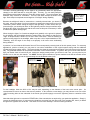
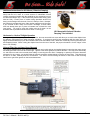
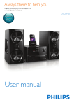
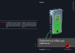
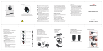
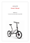
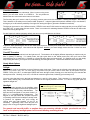
Be Seen... Ride Safe!
Turn-ON Procedure
Two terms that you need to understand: When it comes to the power
button, you can either CLICK it or PRESS it. The only difference
between the two is the time that the button is held down.
The first thing that you’ll notice is that if you simply connect power and click the button… nothing will happen. Don’t worry!
This is because of the safety turn-on feature called “Superlock.” I ship the lights with Superlock enabled, but you can disable it,
as long as you’re OK with the possibility of a single click turning the light on (procedure available on web site).
The light can be turned on into 2 different modes: STEADY mode and FLASH mode, but take note that you must START with
the LIGHT OFF to enter either of these modes. There is no method for switching between STEADY mode and FLASH mode
without first turning the light OFF.
So with Superlock enabled (shipping default), the two turn-on possibilities are as follows:
In practice, when performing the turn-on into flash mode sequence, it’s best just to “hold down” the button on that last PRESS
until you see flashing begin. Note also that with Superlock disabled, you would simply remove the first 2 clicks from both
sequences.
Turn-OFF Procedure
To turn off, simply press-and-hold until the light turns off. The behavior will be slightly different depending on which mode you
were in (steady or flashing). If in steady mode, the light cycles down to the lowest power level, then you’ll see a flash
(indicating that you’ve reached L1), followed by a 2-second safety delay and power down. If in flashing mode, you just simply
keep holding the button (you may see some odd flashing) until the light turns off. This will take between 2 and 3 seconds.
Steady Mode Options
Taillight
Within steady mode for the taillight, you have 5 discrete power level steps. These may be referred to throughout the manual as
Level 1 (L1), Level 2 (L2), etc. To move UP by one power level you CLICK, and to move down by one power level you
PRESS. Once you’re at L1, a subsequent PRESS will cause the light to flash, alerting you to the fact that you’ve reached the
lowest power level. Similarly, once at L5, a CLICK will cause the light to flash, indicating you’re already at L5.
You may notice that the jump in the light level between L1 and L2 is fairly strong. This is because L1 is designated as “limp
home” mode, drawing only a minimal amount of current for the longest possible run times. L1 is also a very good option for
nighttime taillight use.
Headlight
The steady mode operation for the headlight varies
slightly from the taillight and has been optimized for
easy dimming for oncoming vehicles/riders. The
light has been configured to use power levels 2, 3,
and 5 in a low/medium/high arrangement. The
diagram to the right shows the complete sequence
of operating events for the headlight in steady mode.
In practice, for nighttime use, you’ll simply be
clicking back and forth between L3 and L5 as
necessary. “Lightening Flash” mode #4 (see next
page) is also a very good nighttime headlight option.
TIP: Although the diagram shows the turnon process entering L2, it will actually turn
on at the last used power level.
For general road use with traffic, or anytime there are oncoming vehicles at night, you should use L3 or
lower as the primary headlight power level to avoid blinding oncoming drivers.
1
DS User’s Manual: Build 4 and Up
Be Seen... Ride Safe!
Flash Mode Options
Although the new version of the firmware for these lights will allow any of the 6 flash pattern “placeholders” to be completely
customized (refer to the most recent DSFlex Manual for details), the “factory default” patterns have been customized for
DesignShine and are shown below. Flash modes operate identically between the headlight and taillight; however, there a
couple of patterns that were developed specifically for either the head or tail. The first three (in yellow) should be reserved for
daytime only where as the last three (grey) are generally appropriate for night.
DesignShine (Build 4 and up) Flash Patterns
Mode # Quick Name
1
L5 ON/OFF
2
L5 EMS
Description
flash with 400ms delay between bursts.
3
L3 ON/OFF
4
L3/L5
Lightening
Strike
Best Application
Simple on/off flash, roughly 3 per second, at Daytime ONLY, either light. Best for solo riding.
the highest power level.
Slightly longer run times than EMS mode.
Modeled after "Emergency Medical Service" When you need the highest level of recognition, this
is it. Absolutely daytime ONLY.
lights. High intensity rapid (11Hz) 4-burst
***EXTREMELY*** dangerous at night.
Simple on/off flash, roughly 3 per second, at Daytime ONLY, either light. A little more "polite"
level 3.
for group riding, or for daytime battery conservation.
Designed for the headlight, for nighttime. Short L5
burst gives a nice "eye catching" flash, but not long
Solid level 3 operation with 40ms burst to
level 5. You'll find yourself wondering… was enough to be blinding. Very ridable at night since
it's not overly "stroby." NOT RECOMMEND FOR
that lightening?
TAILLIGHT USE AT NIGHT.
5
L1/L2 Triple
Pulse
Solid level 1 operation with 120ms Triple
pulse to level 3.
6
L1/L2 Toggle
Evenly spaced 500ms duration toggling
between level 1 and level 2.
Designed for the taillight, for nightime. The triple
pulse is very effective from dusk to dark at catching
attention in peripheral vision, but not too intense
when looked at directly.
Nice simple, but bold pattern for nighttime taillight.
Use this if you find yourself running low on battery
and you need to extend your run time, or even
better, switch to L1 steady.
While in Flash Mode, switching from one mode to the next is a cyclical operation simply
requiring a CLICK between modes (see right). You may notice about 1 second of delay when
switching between modes 3 and 4 where the light remains off. This is completely normal. You
may also notice on occasion that the light will ignore your CLICK request to switch modes. This
is likely just a small timing issue and totally normal. Note, when you’re in flash mode and pressand-hold to turn the light off, it will remember the particular mode number and come on in that
mode the next time you power up in flash mode.
Determining Battery Status
The head and taillights use the exact same battery monitoring circuitry and logic. However, there
are multiple methods with which you can determine the approximate charge level of the battery.
The first method is with an LED mounted internally on the circuit board which will be visible through the small oval “viewing
window” in the case lid, immediately next to the power button (you may need to shade slightly to view in bright sun). This
method will always be active. Method number two is referred to as “out-the-front/back” indication. In this case, the main LEDs
will be used to “tap out” a simple message (similar to Morse code) from which you can determine the battery status. Note that
when either light is first turned on, you should see a short flash of the on-board LED to indicate the health of the controller.
By default, the headlight comes with the “out-the-front” indication disabled and the taillight has the “out-the-back” indication
enabled. However, just like with every other aspect of the controller, these settings can be changed to suite your preference.
And speaking of making changes to the controller, there are two good resources to help you get started with this. First you
th
should visit the DesignShine Forums site and read the 5 entry to the “All things Batteries” thread. Here you will find a direct
link to download the Reprogramming Instructions PDF file.
http://www.designshinelighting.com/showthread.php?96
Secondly, you can always find THIS manual and the full up user’s manual for the controller board at:
https://sites.google.com/site/designshinelighting/user-manuals
This hard copy will get you started but please go to the USER MANUALS site and read the full document to
understand the battery warning system, along with mounting and safety issues.
2
DS User’s Manual: Build 4 and Up
Be Seen... Ride Safe!
The following table is intended to show you the behavior of the lights’ battery status indication system for every possible
combination of operation mode and approximate battery discharge level. Although I’ve programmed the lights with reasonably
good VOLTAGE detection levels for the 50% and 20% discharge levels, there will be some variation (perhaps significant) from
one battery manufacturer to the next and between fresh vs. old batteries. This is where the “FLEX” in the DSFlex controller
can be very handy. If you find after running your light through a few discharge cycles that you’d like to have a little more or less
warning time for either the 50% or 20% levels, then the voltage thresholds can be easily be changed. Note that even a change
of 0.1V in the threshold levels can make a big difference in the warning times, so I recommend making no more than a 0.1V
change at a time. I also recommend NOT changing the default cutoff threshold value. Full instructions for how to adjust the
warning times can be found again at:
http://www.designshinelighting.com/showthread.php?96
Battery
Level
Internal Status LED
(always active)
Any Mode
Optional Out-the-Front/Back Main LED Indication
(Tail-enabled by default: Head-disabled)
Steady Mode
Flash Mode
Power ON
One short status LED blip to indicate controller heath.
100% to 50% No Status LED Illumination Normal Operation
Normal Operation
Flash pattern suspended momentarily
1 short OFF blip, with 20
with steady burn at the current high
seconds between blips. This
50% to 20% Solid ON
power level for 3 seconds, with a single
warning cycle will continue until
pulse to the current low level after 1.5
discharge reaches 20%.
seconds.
2 short OFF blips, every 20
Same as above only with a double
20% to 1 min Flashing (1 pulse per sec)
seconds until 1 minute warning. pulse.
Flashing (double pulse per 3 short OFF blips, every 20
1min warning
Same as above only with a triple pulse.
sec) until cutoff.
seconds until cutoff.
Main LED will pulse 10 times Main LED will pulse 10 times
Main LED will pulse 10 times then shut
OFF
then shut down.
then shut down.
down.
To gain a full understanding of the battery status reporting, take a look at the battery discharge curve below. This was taken
with a DS-500 taillight running at steady L5 with a Magicshine MJ-6038, 4400mAH battery. The shape of this curve is typical
for lithium-ion with the steepest rolloff occurring at the full discharge levels. Note that the Medium, Low, and Cut-off threshold
voltage levels are all adjustable as needed. The values shown here are the default values loaded into the Build#4 and later
firmware. Although subtle, there will always be some voltage loss in the cable between the battery and light. Higher current
and longer cables will increase this effect. Practically, this means that when running at much lower power levels with lower
current, the points on the horizontal time axis (red dotted lines) will move slightly to the right (on a percentage basis). With the
headlight on L5 drawing more current, they will move slightly to the left (again on a percentage basis). This plot is intended
primarily to instruct you on the status indication system, but it also illustrates the somewhat inexact science of determining run
times. It should also be noted that even after the light has shut off automatically, you will normally be able to turn it on several
more times, for 1-minute intervals, as a last ditch method for getting “out of the woods” until the battery itself hits its internal
protection limit. This option should NOT be used with any unprotected battery packs.
3
DS User’s Manual: Build 4 and Up
Be Seen... Ride Safe!
Run Times
Now that you’ve seen some of the “Logic” behind the battery status indication system, let’s take a look at how to determine
overall run times. Run times are primarily dependent to two factors: total power consumption and battery capacity. To a
lesser degree, run times can be dependent on temperature. In general, if the battery and light are running in sub-freezing
temps, run times are going to be lower by some percentage margin. Your mileage may vary on this one. For the purposes of
these run time calculations, there is an assumption of room temperature. Please note that these numbers represent good
engineering estimates, but there may be some need to tweak up or down depending on a particular battery pack and/or the
relative age of the pack.
The tables below combine empirical test data with the known electrical characteristics of the light to arrive at a best estimate for
the run times at the various power levels and flash modes. Flash mode 4 is a “special condition” for the taillight. Although
borderline acceptable for nighttime use, the “out-the-back” battery indication system will momentarily set the light to steady
level 5 for 3-seconds at 20-second intervals during the medium and low battery periods. Since the “out-the-back” indication is
enabled by default for the taillight, this could result in an un-intentional and dangerous blasting of level 5 at night.
DS-500 Taillight Run Times (Hours)
7.4V Pack (mAH)
7.4V Pack (mAH)
Power Level Lumens
4400
5600
Steady Flashing Steady Flashing
1
111
110.0
140.0
2
239
17.9
22.8
3
378
11.1
14.2
*4
521
7.0
8.8
*5
798
3.5
4.5
Flash mode 1
Level 5 on/off
11.7
14.9
Flash mode 2 Level 5 EMS on/off
10.9
13.9
Flash mode 3
Level 3 on/off
37.3
47.5
Flash mode 4 Level 3/5 Lightening
10.9
13.9
Flash mode 5 Level 1/2 triple pulse
83.7
106.5
Flash mode 6
Level 1/2 toggle
63.9
81.4
Color Legend
Good nightime use
Daytime ONLY, dangerous at night
*Daytime ONLY, good airflow required
for continuous use.
Other Batteries
For batteries of different capacities,
multiply run-time values results at
4400mAH by the ratio:
(desired pack capacity in maH/4400)
A similar headlight runtime analysis was performed and the results are shown below. Take note of the recommended times of
day for the given power levels and flash modes. Ultimately, you need to use good judgment when you set the light so that
you’re not at risk of blinding or dis-orienting the drivers around you. During dusk/dawn and nighttime hours, you should avoid
levels 4 and 5 completely and in general, in low-light settings, flash modes 4 through 6 are preferable since they all use a
pulse/ON technique to avoid the dis-orienting effect of on/off flashing at night. The steady power cycle operation of the
headlight (page 1) is setup specifically to allow easy “dimming” for on-coming traffic with a single click if you find that you prefer
riding at night on level 5.
DS-1300 Headlight Run Times (Hours)
Color Legend
7.4V Pack (mAH) 7.4V Pack (mAH)
Good nightime use
Power Level Lumens
4400
5600 (rec)
Daytime ONLY, dangerous at night
Steady Flashing Steady Flashing *Day or Night use, but avoid with on1
113
44.0
56.0
coming traffic. Good air-flow is required
2
412
9.2
11.7
for continuous use.
3
655
6.2
7.9
*4
908
4.0
5.0
Other Batteries
*5
1402
2.0
2.5
For batteries of different capacities,
Flash mode 1
Level 5 on/off
6.7
8.5
multiply run-time values results at
Flash mode 2 Level 5 EMS on/off
6.2
7.9
4400mAH by the ratio:
Flash mode 3
Level 3 on/off
20.8
26.5
(desired pack capacity in maH/4400)
Flash mode 4 Level 3/5 Lightening
6.1
7.7
Flash mode 5 Level 1/2 triple pulse
34.0
43.3
Flash mode 6 Level 1/2 toggle
26.6
33.8
NOTE: Maximum headlight output will be limited to Level 4 in any mode during the LOW battery warning period.
4
DS User’s Manual: Build 4 and Up
Be Seen... Ride Safe!
Mounting Options
Mounting of the lights is very straight forward, but it’s important to always make sure that your mount is secure and that the
attach point is strong enough to handle the repetitive shock loads due to the mounted weight of the light. Each light with the
extension bar weighs in at roughly 120 grams. Specifications of the mounting hardware are shown below.
#6-32, 5/64" Nylon
patch locking holddown screw.
Cateye H-27
“spacer” aka
quick-release
(headlight only)
Alternate mounting
holes for offset
options.
#8-32, 5/64" Set
screw for locking
position of light.
DS Extender Bar Mounting System
From the diagram above, you can see that there are two screws that are used to hold the light firmly to the extension bar.
Without exception, when setting the angle of the light, you should adhere to the following sequence:
1. Check that the set screw is unscrewed slightly and NOT contacting the housing.
2. Using the provided 5/64” Allan wrench, set the angle of the light and fully tighten the hold-down screw if there is not
already some friction.
3. Lock the angle by lightly tightening the set screw. Do NOT over tighten. Only a small amount of tightening is required.
4. When removing the screws, just the opposite is required. If you try to loosen the hold-down screw before
loosening the set-screw, you may find that it’s almost impossible, and you may damage the head of the screw.
The hold-down screw has a “nylon patch” on the threads, which makes it grab tightly by design. If the screw is removed and
re-inserted multiple times, the locking nylon function will eventually diminish. This is OK. In practice, once the set-screw is
tightened, the extension bar acts like a spring and puts binding forces on both screws to prevent any accidental loosening.
Although the H-27 spacer can be removed, I recommend leaving it on the extender bar. If helmet mounting is desired without
the extender bar, a separate H-27 spacer should be obtained that can be mounted directly to the light body in place of the
extender bar. (Note that the small Philips screw, not shown, on the opposite side of the bar acts as an anti-rotation pin for the
H-27 and is actually threaded into the aluminum bar. This screw should never be over tightened in order to avoid stripping
these threads.
5
DS User’s Manual: Build 4 and Up
Be Seen... Ride Safe!
The basic mounting philosophy for the lights is to permanently attach the appropriate
clamp(s) to the bikes that will be using the lights. This way, you can easily swap the
lights between bikes without having to reset the aiming angles. The quick-release also
facilitates easy removal for commuters. There are two basic clamps as shown to the
right. Both clamps incorporate several degrees of “left/right” aiming capability.
Because the taillight will often be mounted on a vertically oriented tube, you should, in
this case, relieve the clamp of its free movement by rotating the clamp base into its most
“downward” position before setting the angle of the light body. In other words, after you
mount the light, you should push down on the light body until the clamp movement stops.
Re-adjust the angle of the light body with the set screw at this point if necessary in order
to achieve the optimal aiming angle.
When aiming the lights, I’ve found that straight back (parallel) to the ground is optimum
for the taillight, and the headlight should be angled down very slightly so that the front
“edge” of the spot beam is around 15-16’ feet in front of the wheel. There is definitely an
optimum aiming angle for the headlight, which may take a bit of experimentation to find.
Thankfully, once the angle of the camp is set properly it will never move accidentally
during vibration.
H32 “standard”
clamp (10mm
up to 28mm)
H31 “oversize”
clamp (28 to 32
mm)
In practice, I’ve found that the H32 works fine on 27.2mm seat posts by removing both of the thin spacer pieces. For seat-stay
applications, (similar to below) you may need to use some combination of the original spacers along with the additional
included thick spring rubber spacer. The figures below also show the recommend orientation of the H32 clamp on the left seat
stay. Pay particular attention to the preferred orientation of the camlock handle. In general, after your first few rides with the
light, just double check to insure that your mounts are staying exactly where you set them, and if not, you may need to put
another turn on the cam lock handle. You MUST find the right combination of spacer material such that the camlock screw
does not protrude too high into the light mounting area as illustrated below (Left).
Max Height OK
Camlock lever forward.
OK but not ideal.
Camlock lever to the left
is best.
Too high, will damage
spacer
Mounting Clamp Considerations
For the headlight, either the H32 or H31 may be used, depending on the diameter of the bars at the mount point. It’s
recommended to mount as close to the stem as possible. In fact, with the current design, you may choose to use one of the
“offset” mounting holes on the underside of the mount (see previous page) to move the light body closer to centerline of the
stem.
Note that either light can be mounted to EITHER side of the extension bar as required by your particular application. Simply 1)
remove the hold-down screw, 2) remove and re-install the set-screw from the other side of the extender bar, then 3) re-attach
the light to the opposite side of the bar. This allows for even more flexibility in various mounting situations.
6
DS User’s Manual: Build 4 and Up
Be Seen... Ride Safe!
Additional Instructions for H31 Mount (Vibration Damping)
Due to a very subtle change in the mold between the H32 (which is very
solid) and the H31, there is a small amount of undesirable vertical
rocking movement possible with the headlight on the extension bar (not
an issue with taillight use). If this becomes a problem while riding (even
with the H32), a small piece of rubber tubing (standard vacuum line
hose) can be wedged into the hole of the H31 clamp to form a “damper”
and effectively mitigate this issue. Other similar materials could be used.
If you received an H31 clamp for use with a headlight, a small rubber
tube has already been put in place to illustrate how it should be used
(see below). You want to push the rubber tube as far down on the
threaded stud as possible and still have at least ¼” sticking up.
H31 Mount with Optional Vibration
Damping Tube Installed
Horizontal vs. Vertical Taillight Operation
Although the light will ship setup for vertical operation, the new removable lens cover will allow you to reorient the elliptical lens
for optimum performance from either mounting orientation. If you have a need for both orientations with the same light, it is
highly recommended that you pick the orientation that will be used MOST often, rather than continually removing the lens cover
and swapping lenses. When viewing the elliptical lens from the rear of the bike, the proper orientation is for the “ridges” of the
lens to run vertically.
Colored Filter Use and Lens Cover Removal
The colored headlight filters were designed with daytime use in mind and can be installed simply by removing the center screw
and adding the filter to the front face of the light. Tighten to the same tightness as without the filter. The lens cover should stay
on, and does not need to be removed when adding or removing the color filter. If swapping or replacing LED lenses becomes
necessary for any reason, you should follow the general procedure outlined below to remove the lens cover. This should only
be done in a clean, relatively dust-free environment. You want to avoid touching the domes of the LEDs as well as being
careful not to get silicon grease on the lenses themselves.
Lens Cover Removal Process
7
DS User’s Manual: Build 4 and Up
Be Seen... Ride Safe!
The cover is able to be removed and re-installed many times without the need for additional silicon grease. But if it becomes
obvious that a good seal is not being made between the lens cover and o-ring, the silicon grease can be obtained very
inexpensively in the plumbing section of Home Depot or similar stores. A small hobby paint brush would then be used to
LIGHTLY brush a coat of grease around the sealing surface of the clear lens cover. Although unlikely, but if sealing ever
becomes a problem for the small “white” o-rings that seal against the lenses themselves, then a VERY light film of this grease
could also be used at that junction. I would recommend cutting off the head of Q-tip and just using the edge of the paper stick
with an extremely small amount of grease to perform this operation if ever necessary.
Battery Mounting
All build #4 and up lights will be configured for 7.4V li-ion pack use in order to take advantage of the many off-the-shelf options
that are available for powering these lights. When it comes time to replace the battery, a good source compatible batteries is
“Action-LED-lights.com.” In general, any 7.4V battery with the “Magicshine” style 2.1mm power connector will work just fine.
When you received your light, you may have also received a spare wired power connector. This is for your “future” use, if you
ever find that you need to adapt a “generic” battery to the proper power connector.
In most cases for stand-alone taillight or single-battery, dual light use, battery mounting will consist of stowing the battery in a
saddle bag. However, in the for solo headlight use, many batteries use a Velcro or otherwise strap system to secure the
battery to the underside of the stem or a section of tubing as shown below. When mounting the battery under the stem, be
sure to prevent any binding or rubbing of the battery on any portion of the non-rotating steerer tube.
When using a strap, it’s important to get as much cinching force on the battery as possible for a secure mount. In
general, you will want to position the “D” ring of the strap on the TOP of the tube so that you can very tightly cinch the strap by
pulling down before making the Velcro connection. If your strap has a slight bit of “stretch” to it, you should pull it tightly
enough to begin to feel this slight stretch before you cinch it down.
Typical Stand-Alone Headlight Battery Mounting Locations
Battery Charging and Maintenence
Lithium-ion battery charging and care are relatively simple and require that only a few good habits be established
for maximum life, regardless of the brand of the battery.
1. Always charge the battery in a room-temperature environment. Be especially cautious to NEVER charge
the battery below freezing.
2. Plug in the charger first (green light will come on), then plug in the battery. If the battery is depleted low
enough, the light will turn red and stay red until charging is complete. If the battery is nearly full, then the
light may remain green when the battery is plugged in.
3. Remove the battery from the charger as soon as reasonably possible after the charge cycle is complete.
4. If you plan to store the battery unused for more than a month, it is recommended to first drain the battery to
HALF CHARGE. Storing a battery with a full charge will quickly diminish its capacity. Li-ion cells in general
have a “life span” independent of the number of charge cycles. So even if the pack is not used, its life
expectancy is still only 2 to 3 years, which is typical for the li-ion chemistry.
5. Charging an empty 4400maH pack will take anywhere from 5 to 7 hours with a low-cost automatic 1-amp
charger. More or less time will be required for higher or lower capacity packs, respectively.
8
DS User’s Manual: Build 4 and Up
Safety Precautions and Warranty
Heating
These lights have very robust heat management characteristics, designed to prevent any damage to YOU or to the LEDs
and electronics. But still, you should exercise extreme care when operating the light in a no air-flow environment.
Definitely KEEP OUT OF REACH OF CHILDREN.
To increase your own understanding of the limits of operation, try this experiment. With the lights indoors and sitting on a
hard surface (or mounted on the bicycle), turn the lightt on steady at level 5 (high). Watch and periodically feel the light
until you see the light level automatically drop down to a lower level (somewhere between 4 and 6 minutes later). At this
point, carefully and momentarily touch the case of the light at various places. It will be very hot, in fact slightly painful if
you were to hold it for an extended amount of time, but not quite hot enough to burn you. Make a mental note of how this
feels. This should be the hottest that the headlight ever gets, and the temperature trip point has been chosen to provide
the optimum usability level on the bike, so that momentary stops on the bike do not have time to trip the thermal protection
circuit. In fact, even a mild breeze will generally allow sustained Level 5 operation.
Colored Lenses
The colored lens covers should be handled carefully, and do avoid wiping it if dry to avoid scratching. Unlike the clear
lens cover (which is made from high temperature polycarbonate), the colored lenses are Acrylic and not as tolerant to high
temperatures. As such, it is recommended that you only use the colored lenses in flashing modes and preferably only
outdoors to avoid any excess heat damage to the clarity of the filter. This is very unlikely, but worth mentioning.
As you know, these lights are EXTREMELY powerful, so here goes with the “official” disclaimers (please do take the time
to read them all or my wife is going to make me call a lawyer ;) Most of these fall into the “common sense” category, but I
had to state them. See website for full disclaimer.
1. Never, under any circumstances look directly at the lights from close range (while in your
hand) or point the lights directly at anyone’s eyes at close range.
2. Never shine the light directly on your skin from close range (1/8” inch or less) It CAN burn
you if you leave it there too long.
3. Never use level 4 or 5 on the taillight at night, and it is highly recommended that you run
the taillight in steady mode at night (or appropriate flash mode). When using level 5 on
the headlight at night, please be comfortable enough with the operation of the light to be
able to dim quickly to level 3 or lower for oncoming cars.
4. Never turn the lights on and leave un-attended. If the heat sink fins were partially
blocked, overheating and damage is a possibility with long periods of operation with no
airflow.
5. Never turn the lights on and leave in contact with flammable materials.
6. If at any time you find the light has become too hot to touch and/or to press and hold the
button to turn-off, simply disconnect the battery wire (normally this should not happen).
7. NEVER under any circumstance leave the battery pack in an un-attended car that is
going to be left in the sun for any length of time. In other words, do not expose the battery
to excessive heat. All charging and storage environments should be near room
temperature for best performance.
8. DO take care not to drop the battery onto hard surfaces. They contain an immense
amount of energy in a very small package. At any sign of trauma or damage to the
battery, you should immediately discontinue use, dispose of safely, and replace with a
new pack.
Warranty
These lights are tough… really tough, and should provide you with years of trouble free service due to the extreme level of
over-engineering. If anything breaks in the first year, just send it back for repair. All you need to do is pay the postage to
ship it to me. Accidents do happen though, so even if you do manage to damage the plastic bits, or the power cable
several years down the road, I can replace these things for you a minimal cost. Just email me first at:
[email protected]. All mail correspondence should go to 137 Holbrook Drive, Huntsville AL, 35806. Since
I’m only a “pass-through” battery provider, I can only help with battery issues to the extent that they are covered by the
original supplier.
9
DS User’s Manual: Build 4 and Up