1
Appendix A: Connections
A.1. Pin Assignment
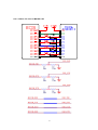
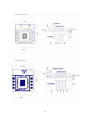
A.1.1. Parani-ESD100/110
Pairing DCD
DSR DTR
RST GND
7
8
9
10
11
12
1
2
3
4
5
6
CTS
VDD
GND TXD
RXD RTS
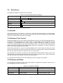
Figure A-1 Pin Assignment of Parani-ESD100/110
Table A-1. Pin Assignment of Parani-ESD100/110
Pin #
Signal
Direction
Description
Signal Level
1
GND
-
Power Ground
Ground
2
TxD
Output
UART Data Output
TTL
3
RxD
Input
UART Data Input
TTL
4
RTS
Output
UART Ready to Send
TTL
5
CTS
Input
UART Clear to Send
TTL
6
VDD
Input
DC Input (3.0~3.3V)
Power
7
Pairing
Input
Pairing Input (Active Low)
TTL
8
DCD
Output
Bluetooth Connect Detect (Active Low)
TTL
9
DSR
Input
Data Set Ready
TTL
10
DTR
Output
Data Terminal Ready
TTL
11
RST
Input
Reset (Active Low)
TTL
12
GND
-
Power Ground
Ground
29