1
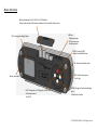
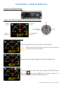
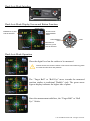
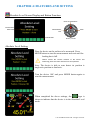
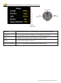
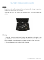
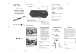
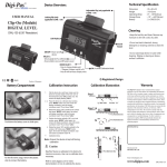
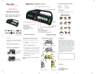
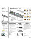
Digi-Pas
®
Innovation & Technology Driven™
USER MANUAL
2-Axis Precision Digital Level
Model: DWL2000XY
www.digipas.com
Note: Contents in this instruction manual is continuously updated, please check Digi-Pas website for latest version.
REVISION 1.00
INTELLECTUAL PROPERTY
This manual contains propriety information, which is protected by copyrights. All rights
are reserved. No part of this manual may be photocopied, reproduced, redistributed or
translated to another language without prior written consent of JSB TECH Company.
The information in this manual was correct at the time of printing, stored in CD or
uploaded in the Company website. However, JSB TECH will continue to improve
products and reserves the rights to change specification and maintenance procedures at
any time without prior notice.
Digi-Pas® Products were manufactured under ISO9001 & ISO14001 standards,
tested to comply by the followings certification bodies:
®
© 2012 JSB TECH Pte Ltd. All rights reserved. Digi-Pas logo is registered trademarks of JSB TECH Pte Ltd.
CONTENTS
CHAPTER 1: DEVICE OVERVIEW
- Technical Specification
- Overview
CHAPTER 2: SETTING UP
- Operating Procedure
- Mounting Device on Fixture
CHAPTER 3: USER INTERFACE
- Single Axis Mode Interface
- Dual Axis Mode Interface
- Main Menu Icon Functions
CHAPTER 4: FEATURES AND SETTING
- Absolute Level
- Alternate Zero
- Setting Menu
CHAPTER 5: STORAGE AND CLEANING
CHAPTER 6: WARRANTY
APPENDIX: USER CALIBRATION
© 2012 JSB TECH Pte Ltd. All rights reserved.
CHAPTER 1: DEVICE OVERVIEW
Technical Specification
DWL2000XY
Measurement Range
(Single Axis Mode)
Measurement Range
( 2-Axis Mode)
0.00° to ± 90.00°
0.00° to ± 3.00°
Resolution
0.01° (175µm/M) (0.002 in/ft)
Accuracy
± 0.02° at 0.00° ~ ± 2.00° (349µm/M)
(0.004 in/ft) (72 Arcsec)
± 0.04° at other angle
Repeatability
Cross Axis Error
Display
Power Supply *
Material
Connectivity
PC SYNC Software
Operating Temperature
Dimension (mm)
Nett Weight (Approx.)
User Self Calibration
0.01° (175µm/M) (0.002 in/ft)
Negligible (± 0.0025°)
Colour TFT LCD
4 x AAA 1.5V Batteries / USB
PC ABS / Aluminium
USB 2.0 Cable (≤ 5 metre)
Professional Edition (Optional)
-10°C to +50°C (Calibrated)
14°F to 122°F (Calibrated)
188 x 62 x 37
580 gram
Yes
Specifications are subject to change without notice.
*Alterative Device power can be obtained from External USB Power Source .
Note:
Product performance to specification are verified by Accredited Calibration & Test Providers in USA, Japan, UK and
Germany to conform with NIST, JIS, UKAS & DIN under the International Laboratory Accreditation Cooperation (ILAC)
and American Association for Laboratory Accreditation (A2LA). For more information, please visit
“www.digipas.com/Calibration.html” .
© 2012 JSB TECH Pte Ltd. All rights reserved.
Device Overview
Battery Compartment of 4 x “AAA” size 1.5V batteries.
-Observe the polarity of the batteries indicated on the top of the battery cover
LCD Colour graphic digital display
USB Port:
- USB power supply
- PC Synchronization
- Firmware update
ON/OFF: Power On/Off
- Escape from Mode function
CAL: Activate calibration mode
HOLD: Freeze display value
- Scroll right
Buzzer sound alert
UNIT: Change the unit (⁰ (degree), mm/M, In/FT)
of the measurement
- Scroll left
MODE: Change the function and display
mode
- Selection the function
© 2012 JSB TECH Pte Ltd. All rights reserved.
CHAPTER 2: SETTING UP
Operation Procedure
1. Insert 4 pieces of "AAA" batteries into the battery compartment and press ON/OFF button. Alternatively,
insert USB power source to the USB Port to power up the device. Take note that the device performance
might be affected when poorly regulated USB power source is used.
Battery: 4 x “AAA” size 1.5V batteries
(Take note on the battery’s polarity as indicated on top of the battery cover)
USB Port
2. Allow sufficient time for device to warm up and stabilise after turning on the device.
3. Device ready to use.
Note: For maximum accuracy, perform calibration (refer to APPENDIX: User Calibration) or Absolute
Level (refer to Chapter 4: Absolute Level for more details) before measurement.
Mounting Device On Fixture or Work Piece
The two threaded holes are provided for mounting the device onto user-defined fixtures/machinery.
User defined fixture/machinery
To mount the device onto user’s defined fixture or work piece. Remove both the set screw (M5), then
replace with appropriate type of screws specified by user.
© 2012 JSB TECH Pte Ltd. All rights reserved.
CHAPTER 3: USER INTERFACE
Single Axis Mode Interface
Single Axis Mode Display Screen and Button Function
OFF
BATTERY
LEVEL
SOUND
ALERT
MEASUREMENT
UNITS
DIGITAL
READING
MEASUREMENT
UNITS
HOLD
MAIN MENU
Single Axis Mode Operation
Place the digital level on the surface to be measured.
Please ensure the contact surfaces of the device and measuring plane
are clean and free from dust particles.
The green arrow sign on display indicates the higher side.
User may “freeze” the screen by pressing the HOLD button.
The icon
pops up to indicate the screen is paused. To
resume operation, press the hold button once.
© 2012 JSB TECH Pte Ltd. All rights reserved.
Dual-Axis Mode Interface
Dual-Axis Mode Display Screen and Button Function
SOUND ALERT
BATTERY LEVEL
MEASUREMENT
UNITS
HORIZONTAL (X) AXIS
DIGITAL READING
OFF
MEASUREMENT
UNITS
MICROMETER
HOLD
VERTICAL (Y) AXIS
DIGITAL READING
MAIN MENU
Dual-Axis Mode Operation
Place the digital level on the surface to be measured.
Please ensure the contact surfaces of the device and measuring plane
are clean and free from dust particles.
The “Target Ball” or “Bull Eye” move towards the measured
position similar to traditional "Bubble" vials. The green arrow
sign on display indicates the higher side of plane.
Once the measurement stabilizes, the “Target Ball” or “Bull
Eye” blinks.
© 2012 JSB TECH Pte Ltd. All rights reserved.
Main Menu Icon Screen Display and Button Function
TITLES
EXIT MAIN MENU
ICONS
CURSOR
SCROLL LEFT
SCROLL RIGHT
SELECT / ENTER
Main Menu Icon Features
ABSOLUTE LEVEL SETTING
Enable user to ensure each measurement reading is in accordance to
maximum device accuracy specified.
ALTERNATE ZERO SETTING
Enable user to measure relative angles at a common plane with
respect to a reference angle. Set any angle to 0.00⁰ as a reference.
SETTING MENU
Enable user to modify various parameters of the device.
HELP MENU
Enable user to have a quick and easy reference on Device’s button
configuration.
© 2012 JSB TECH Pte Ltd. All rights reserved.
CHAPTER 4: FEATURES AND SETTING
Absolute Level Screen Display and Button Function
BACK TO MAIN MENU
INSTRUCTION
INDICATOR
MEASUREMNT
UNIT
LOADING BAR
HOLD
SELECT / ENTER
Absolute Level Setting
Place the device on the surface to be measured. Press
MODE button to start the measurement and wait until the
loading bar is full.
Please ensure the contact surfaces of the device and
measuring plane are clean and free from dust particles.
Note: The device is able to auto detect its position is
single axis position or dual-axis.
Turn the device 180° and press MODE button again to
start the measurement.
When completed the above settings, the
logo is
shown to indicate that the device is in the Absolute Level
mode.
© 2012 JSB TECH Pte Ltd. All rights reserved.
Alternate Zero Screen Display and Button Function
BACK TO MAIN MENU
INSTRUCTION
MEASUREMNT
INDICATOR
UNIT
HOLD
SELECT / ENTER
SINGLE OR Dual-AXIS INDICATOR
Alternate Zero Setting
Place the digital level on the surface to be measured. Press
MODE button to set the angle to 0⁰ as a reference.
Please ensure the contact surfaces of the device and measuring
plane are clean and free from dust particles.
Note: The device is able to auto detect its position is single
axis position or 2-axis.
Single Axis Position
The
logo is shown to indicate that the device is in
Alternate Zero mode. A reference line is displayed to indicate
the angle.
Dual Axis Position
The
logo is shown to indicate the device is in the
Alternate Zero mode. A reference crosshair is displayed to
indicate the real angle.
© 2012 JSB TECH Pte Ltd. All rights reserved.
Setting Menu Display Screen and Button Function
MAIN MENU
RIGHT
SELECTION
LEFT
SELECTION
DOWN
SETTING
PARAMETERS
AutoOff
To set automatic power off according to user defined time period.
AutoDim
To set automatic dim according to user defined time period.
Units
To change the measuring unit (Degree, mm/M, In/FT).
Buzzer
To turn on/off the device buzzer.
Display Brightness To set LCD brightness according to user defined level.
© 2012 JSB TECH Pte Ltd. All rights reserved.
CHAPTER 5: STORAGE AND CLEANING
Storage
Keep the device in the equipment box and maintain the storage temperature
within -20°C to 60°C or -4°F to 140°F.
When the device is not in used, the batteries are to be removed from the
device.
Cleaning
1. Keep the device dry and clean. Remove any moisture or dirt with a soft
dry cloth before measurement to obtain the maximum accuracy. Do not use
harsh chemicals, strong detergents or cleaning solvent to clean the device.
2. Do not submerge device in liquid while cleaning.
© 2012 JSB TECH Pte Ltd. All rights reserved.
CHAPTER 6: WARRANTY
®
Digi-Pas 2-Axis High Precision Digital level is warranted to the original purchaser to be free from defects in
workmanship and material. JSB Tech will, at its option, repair or replace any defective part which may
malfunction under normal and proper use within a period of 2 (two) years from the date of purchase. The
forgoing warranty shall not apply to defects resulting from misuse, abuse, assignment, or transfer by the Buyer.
Buyer-supplied software or interfacing, unauthorized modification or operation outside of environment
specifications for the product. JSB Tech does not warrant that the operation of instrument software, or
firmware, will be uninterrupted or error free. The exclusive remedy under any and all warrants and guarantees,
expressed herein, and we shall not be liable for damages from loss or delay of equipment uses, consequential,
or incidental damage. No other Warranty is expressed or implied. JSB Tech specifically disclaims the implied
warranties of merchantability and fitness for a particular purpose.
Distributed by:
Manufactured by:
JSB TECH PTE LTD
Email:[email protected]
www.digipas.com
JIM-2-02001-99
© 2012 JSB TECH Pte Ltd. All rights reserved.
APPENDIX: USER CALIBRATION
Calibration Instruments:
Grade AA (Levelled to ≤1.0 arcsec)
Granite Table
Flatness : ≤ 2.0µm
Master Square
Perpendicularity: ≤ 2.0µm
Parallelism: ≤ 2.0µm
Master Square
Granite Table
Calibration Procedures:
Ensure the DWL3000XY device is in power OFF
condition. Press and hold the CAL button by using a small
pin and simultaneously press the ON/OFF button. The
LCD screen displays “Calibration 1” .
1. Place the device to Position 1. Press the MODE button
once and wait until the countdown reach “0”, the LCD
screen displays “Calibration 2” .
Position 1
2. Turn the device 180° to Position 2. Press the MODE
button again to start the calibration at “Position 2” and
wait until the countdown reach “0”, the LCD screen
displays “Calibration 3”.
Position 2
3. Place the device 90° on the side of Master Square as
shown in Position 3. Hold the device firmly and do not
move the device during each count down period. Press
the MODE button again to start the calibration and wait
until the countdown reach “0”, the LCD screen displays
“Calibration 4” .
Position 3
© 2012 JSB TECH Pte Ltd. All rights reserved.
4. Turn the device 180° and place on the opposite side of the
master square as shown in Position 4. Hold the device
firmly and do not move the device during each count
down period. Press the MODE button again to start the
calibration and wait until the countdown reach “0”, the
LCD screen displays “Calibration 5” .
Position 4
5. Rotate the device 180° as shown Position 5. Hold the
device firmly and do not move the device during each
count down period. Press the MODE button again to start
the calibration and wait until the countdown reach “0”,
the LCD screen displays “Calibration 6” .
Position 5
6. Turn the device 180° and place on the opposite side of the
master square as shown in Position 6. Hold the device
firmly and do not move the device during each count down
period. Press the MODE button again to start the
calibration and wait until the countdown reach “0”, the
LCD screen displays “Calibration 7” .
Position 6
7. Place the device to Position 7. Press the MODE button
once and wait until the countdown reach “0”, the LCD
screen displays “Calibration 8” .
Position 7
8. Turn the device 180° to Position 8. Press the MODE button
again and wait until the countdown reach “0”, the LCD
screen will switch to measuring mode once calibration is
completed.
Position 8
Precaution:
To achieve maximum accuracy, the device must be held firmly on to jig during calibration process. Any
movement on countdown during each calibration procedure would affect device accuracy.
© 2012 JSB TECH Pte Ltd. All rights reserved.