Download All-In-One Camera HD
Transcript
HD-SDI PTZ Outdoor All-In-One Camera User’s Manual Ver. 0.5 / 2011.03 Safety Information CAUTION RISK OF ELECTRIC SHOCK. DO NOT OPEN. CAUTION: TO REDUCE THE RISK OF ELECTRIC SHOCK, DO NOT REMOVE COVER (OR BACK) NO USER SERVICEABLE PARTS INSIDE. REFER SERVICING TO QUALIFIED SERVICE PERSONNEL. Warning Precaution This symbol indicates that dangerous voltage consisting a risk of electric shock is present within this unit. This exclamation point symbol is intended to alert the user to the presence of important operating and maintenance (servicing) instructions in the literature accompanying the appliance. WARNING Precautions Operating • Before using, make sure power supply and others are properly connected. • While operating, if any abnormal condition or malfunction is observed, stop using the camera immediately and then • contact your Special dealer. To prevent damage which may result in fire or electric shock hazard, do not expose this appliance to rain or moisture. WARNING 2. Be sure to use only the standard adapter that is specified in the specification sheet. Using any other adapter could cause fire, electrical shock, or damage to the product. Handling • Do not disassemble or tamper with parts inside the camera. • Do not drop or subject the camera to shock and vibration as this can damage camera. • Care must be taken when you clean the clear dome cover. Especially, scratch and dust will ruin your quality of camera. 3. Incorrectly connecting the power supply or replacing battery may cause explosion, fire, electric shock, or damage to the product. 4. Do not connect multiple cameras to a single adapter. Exceeding the capacity may cause abnormal heat generation or fire. Installation and Storage • Do not install the camera in areas of extreme temperature, which exceed the allowable range. • Avoid installing in humid or dusty places. • Avoid installing in places where radiation is present. • Avoid installing in places where there are strong magnetic fields and electric signals. • Avoid installing in places where the camera would be subject to strong vibrations. • Never expose the camera to rain and water. 5. Securely plug the power cord into the power receptacle. Insecure connection may cause fire. 6. When installing the camera, fasten it securely and firmly. A falling camera may cause personal injury. 7. Do not place conductive objects (e.g. screw drivers, coins, metal things, etc.) or containers filled with water on top of the camera. Doing so may cause personal injury due to fire, electric shock, or falling objects. 8. Do not install the unit in humid, dusty, or sooty locations. Doing so may cause fire or electric shock. 9. If any unusual smells or smoke come from the unit, stop using the product. In such case, immediately disconnect the power sorce and contact the service center. Continued use in such a condition may cause fire or electric shock. 10. If this product fails to operate normally, contact the nearest service center. Never disassemble or modify this product in any way. 11. When cleaning, do not spray water directly onto parts of the product. Doing so may cause fire or electric shock. 2 Important Safety Instructions 1. Read these instructions. - All these safety and operating instructions should be read before the product is operated. 2. Keep these instructions. - The safety, operating and use instructions should be retained for future reference. 3. Heed all warnings. - All warnings on the product and in the operating instructions should be adhered to. 4. Follow all instructions. - All operating and use instructions should be followed. 5. Do not use this apparatus near water. - For example: near a bath tub, wash bowl, kitchen sink, laundry tub, in a wet basement; near a swimming pool; etc. 6. Clean only with dry cloth. - Unplug this product from the wall outlet befor cleaning. Do not use liguid cleaners. 7. Do not block any ventilation openings. Install in accordance with the manufacturer’s instructions. - Slots and openings in the cabinet are provided for ventilation, to ensure reliable operation of the product, and to protec it from over-heating. The openings should never be blocked by placing the product on bed, sofa, rug or other similar surface. This product should not be placed in a built-in installation such as a bookcase or rack unless proper ventilation is provided and the manufacturer’s unstructions have been adhere to. 8. Do not install near any heat sources such as radiators, heat registers, or other apparatus (including amplifiers) that produce heat. 9. Do not defeat the safety purpose of the polarized or grounding-type plug. A polarized plug has two blades with one wider than the other. A grounding type plug has two blades and a third grounding prong. The wide blade or the third prong are provided for your safety. If the provided plug does not fit into your outlet, consult an electrician for replacement of the obsolete outlet. 10. Protect the power cord from being walked on or pinched particularly at plugs, convenience receptacles, and the point where they exit from the apparatus. 11. Only use attachments/accessories specified by the manufacturer. 12. Use only with cart, stand, tripod, bracket, or table specified by the manufacturer, or sold with the apparatus. When a cart is used, use caution when moving the cart/apparatus combination to avoid injury from tip-over. 13. Unplug this apparatus during lightning storms or when unused for long periods of time. 14. Refer all servicing to qualified service personnel. Servicing is required when the apparatus has been damaged in any way, such as power supply cord or plug is damaged, liquid has been spilled or objects have fallen into the apparatus, the apparatus has been exposed to rain or moisture, does not operate normally, or has been dropped. 3 Disposal of Your Old Appliance 1. When this crossed-out wheel bin symbol is attached to a product it mean the product is covered by the European Directive 2002/96/EC. 2. All electrical and electronic products should be disposed of separately form the municipal waste stream via designated by the government or the local authorities. 3. The correct disposal of your old appliance will help prevent potential negative consequences for the environment and human health. 4. For more detailed information about disposal of your old appliance, please contact your city office, waste disposal service or the shop where you purchased the product. This equipment has been tested and found to comply with the limits for a Class A digital device, pursuant to part 15 of the FCC Rules. These limits are designed to provide reasonable protection against harmful interference when the equipment is operated in a commercial environment. This equipment generates, uses, and can radiate radio frequency energy and, if not installed and used in accordance with the instruction manual, may cause harmful interference to radio communications. Operation of this equipment in a residential area is likely to cause harmful interference in which case the user will be required to correct the interferenece at his own expense. 4 Contents 4 Precautions 1. Introduction 6 Product & Accessories 7 Parts Name & Functions_Appearance 8 Parts Name & Functions_Inside 2. Installation 9 Installation 13 DIP Switch Setup 15 Cabling 3. OSD Menu 17 Check Points before Operation 18 OSD - ROOT MENU & SYSTEM INFORMATION 19 OSD - MOTION SETUP 20 OSD - FUNCTION SETUP > PRESET SETUP 21 OSD - FUNCTION SETUP > SCAN SETUP 22 OSD - FUNCTION SETUP > PATTERN SETUP 23 OSD - FUNCTION SETUP > GROUP SETUP 25 OSD - CAMERA SETUP > WB SETUP 26 OSD - CAMERA SETUP > AE SETUP 27 OSD - CAMERA SETUP > OTHER SETUP 28 OSD - SYSTEM SETUP 4. Specification 29 Dimensions 5 1 Introduction - Product & Accessories Product Accessories Hexagonal Wrench Manual CD All-In-One Camera 6 Quick Manual 1 Introduction - Part Name & Functions_Appearance Sunshield & Upper Housing 1 PTZ Mechanism 2 Dome Safety Wire 3 Dome Cover 4 3 Dome Safety Wire 1 Sunshield & Upper Housing Prevents the dome cover from falling. Sunshield protect bubble dome cover from the sun rays and rain fall. In the sunshield, there is the upper housing which will contain accommodate PTZ mechanism. Also, the upper housing will be connected to both mounting brackets and dome cover. 4 Dome Cover Do not detach protection film from dome cover before finishing all installation process to protect dome cover from scratches or dust. In the dome cover, there are fan and heater to remove moisture on the bubble dome. 2 PTZ Mechanism Control the PTZ operations of the camera. 7 1 Introduction - Part Name & Functions_Inside 6 2nd Video Output Port Video Coxial Cable 1 7 ID Setup Switch Alarm Output Port 2 8 Communication Setup Switch Alarm Input Port 3 9 RS-485 Port Fan 4 10 Power Port Heater 5 6 2nd Video Output Port 1 BNC Coxial Cable Video out check the screen during installation. Connects to video output device such as monitor using the BNC coaxial cable. 7 ID Setup Switch Specify the camera ID. 2 Alarm Output Port It connects to the alarm lights, siren or lamps, and it is activated according to the OSD menu or ‘Setup’ on the Web -viewer setting. 8 Communication Setup Switch Set the transfer rate and protocols. 9 RS-485 Port 3 Alarm Input Port Used for RS-485 communications. It connects to IR sensor, IrDA sensor or door switch. If the sensor is activated, it can activate to move camera to the specific angle and to connect the alarm device. 10 Power Port Connect the power source here. 4 Fan Defrosts the dome cover and removes moisture. 5 Heater Defrost the dome cover in a low temperature by increasing the internal temperature of the housing. 8 2 Installation - Installation 5 You have to detach the PTZ mechanism from the upper housing to plug the connector of cable. When detach PTZ mechanism, pressing down and holding up the black handles in both sides of PTZ mechanism. 6 [1] Wind the water proof tape on the pipe of upper housing. [2] Hooking the safety wire on the hole of pipe. [3] Attach the upper housing to wall mount bracket by turning it at least seven turns. [3] [1] To fix the upper body orientation, turn the handle of double nuts to clockwise tightly. [2] 9 2 Installation - Installation 7 Connect each of the following cables to the applicable port and set the DIP switch to configure the camera ID, communication protocol. a b c a c b d e d f e f Alarm Output Port Alarm Input Port DIP Switch for Camera ID Setup DIP Switch for Communication RS-485 Port Power Port Refer to 13, 14 page for detail DIP switch setting. Refer to 15, 16 page for detail cablings. 8 Make sure that the dome cover is connected firmly to the safety wire. 10 2 Installation - Installation 7 Plug the connector of cable from junction box into properly. After checking the orientation of one touch connector in the upper housing, press the PTZ mechanism into hook in the upper housing. 8 To lock the PTZ mechanism to the upper housing, press the two black handles till it sounds snap. 11 2 Installation - Installation 9 Close the dome cover. Care must be taken to locate dome cover by matching the ‘Arrow Mark’. Arrow Mark Arrow Mark 10 Tighten four screws on the dome cover in sequence as shown in the picture. To maintain the best sealing, the torque of each screw must be in the range between 0.5 ~ 1.0 N·m(0.3 ~ 0.73 lbf·ft). 12 2 Installation - DIP Switch Setup Before installing the camera, you should set the DIP switch to configure the camera ID, communication protocol. 5 Panasonic ON Interface Board 1 2 3 4 5 6 7 8 4 5 6 7 8 6 7 8 6 GE(Kalatel) ON 8J 1 2 3 ON 8J 1 2 Protocol Setup 3 4 5 6 7 7 AD(American Dynamics) 8 ON Baud Rate Setup RS-485 Termination Resistor 8J 1 2 3 4 5 6 7 8 3 4 5 6 7 8 3 4 5 6 7 8 3 4 5 6 7 8 2 PELCO-D ON 2 3 PELCO-P ON 2 4 SAMSUNG ON 8J 1 5 - If you change camera protocol by changing DIP switch, the change will be effective after you reboot the camera. ON 8J 1 4 - If you want to control using DVR or system keyboard, their protocol must be identical to camera. Otherwise, you can not control the camera. 1 Auto - Factory Default 8J 1 3 - If you set the protocol as ‘Auto’ protocol, camera will automatically recognize PELCO-D or PELCO-P protocol. 1. Communication Protocol Setup Select the appropriate protocol with DIP switch combination. 8J 1 2 2 13 2 Installation - DIP Switch Setup 2. Communication Baud Rate Setup Select the appropriate baud rate with DIP switch combination. 3. RS-485 Termination Resistor ON 1 2400 BPS - Factory Default ON 8J 1 8J 1 2 3 4 5 6 7 8 2 3 4 5 6 7 8 - Pin 8 is used for on/off of RS-485 termination. - Normally, it must be off state. - Especially, when you have trouble with long daisy chain style connection, turn on this termination switch of the last camera. 2 4800 BPS ON 4. Camera ID Setup 8J 1 2 3 4 5 6 7 8 3 4 5 6 7 8 Interface Board 3 9600 BPS ON 8J 1 2 ID number of camera is set using binary number. The example is shown below. 4 19200 BPS ON 8J 1 2 3 4 5 6 7 8 Pin 1 2 3 4 5 6 7 8 ID Value 1 2 4 8 16 32 64 128 ex) ID=5 on off on off off off off off ex) ID=10 off on off on off off off off - If you want to control a certain camera, you must match the camera ID with ‘CAM ID’, setting of DVR or keyboard controller. 5 38400 BPS ON - ID number of the camera is set using binary number. - The range of ID is 0~255. 8J 1 2 3 4 5 6 7 - Factory default of camera ID is 1. 8 - Camera ID will be effective without rebooting the camera. 14 2 Installation - Cabling 1 Video Output AC 24 V F.G RS 2 Power 3 RS-485 Communication (DVR/Keyboard) Connects to video output device such as monitor using the BNC coaxial cable. For PTZ control, connect this line to keyboard and DVR. To control multiple cameras at the same time, RS-485 communication lines of them are connected in parallel as shown below. 2 Power Connection Please, check the voltage and current capacity of rated power carefully. AC 24V 5 3 RS-485 (Keyboard Controller/DVR) 1 Video Output Rate Power -48 Current Consumption Heater Off: 24W Heater On: 55W RS-485 PoE Keyboard Controller/DVR 802.3at class 4 ~ Coil up the power cable to the Ferrite Core. It will control the electromagnetic waves of Power Cable. #1 15 #2 #n 2 Installation - Cabling Alarm Input Alarm Output 1 2 AL 3 4 AR MI N GN PUT D 5 6 7 8 In 1 COM In 8 5 Alarm Input/Sensor OU T1 OU T2 OU T3 OU T4 6 Alarm Output 5 Sensor Input/Sensor 6 Alarm Output If you want to use alarm input, the types of sensor must be selected in OSD menu. The sensor types are ‘Normal Open’ and ‘Normal Close’. If sensor type is not selected properly, the alarm can be activated reversely. 1 In 1 There are 4 alarm outputs and all of them are relay contact type. Therefore, you do not have to care about polarity, AC/DC, and isolations between channels. Care must be taken for the power capacity of relay contact written above. Out 2 3 AL 4 M IN GN PUT D 5 Out OU AR T1 OU T2 6 7 OU T3 8 OU T4 COM N.O In 2 COM Activation In 2 COM N.C In 2 COM Activation In 2 COM It is noted that short circuit between GND and Input pin means alarm activation. 16 3 OSD - Check Points before Operation Check Points before Operation 1. Before power is applied, please check the cables carefully. 2. The camera ID of the controller must be identical to that of the camera to be controlled. The camera ID can be check in the system information of OSD menu. 3. If your controller supports multi-protocols, the protocol must be changed to match to that of the camera. 4. If you changed camera protocol by changing DIP switch, the change will be effective after you reboot the camera. 5. Since the operation method can be different for each controller available, refer to the manual for your controller if camera cannot be controlled properly. 1 Preset and Pattern Function Pre-check - Check how to operate preset, pattern, scan and group function with keyboard controller/DVR in advance to operate camera function using them. (Refer to your system keyboard manual) 2 Start OSD Menu Using the OSD menu, preset, pattern, scan, group and alarm input function can be configured for each application. Enter ‘Preset key + 95’. 17 3 1 OSD - ROOT MENU & SYSTEM INFORMATION 1 ROOT MENU ROOT MENU ==================================================== <SYSTEM INFORMATION> <MOTION SETUP> <FUNCTION SETUP> <CAMERA SETUP> <SYSTEM SETUP> <SYSTEM INFORAMTION> Shows information and current configuration. <MOTION SETUP> Setup for motion related settings. <FUNCTION SETUP> Setup for various functions such as preset, scan, pattern, group and schedule. EXIT <CAMERA SETUP> Configure camera related functions and data. <SYSTEM SETUP> Configure for basic system setup. 1 <SYSTEM INFORMATION> ==================================================== FIRMWARE HD-SDI PROTOCOL BAUD RATE CAMERA ADDRESS BACK EXIT v0.52_110311 [18] 1920x1080i60 Pelco-D 2400 1 1 SYSTEM INFORMATION FIRMWARE VER Shows the current firmware version. HD-SDI Shows the current resolution of HD-SDI. PROTOCOL Shows the current PTZ control protocol. BAUD RATE Shows the current baud rate of the PTZ control. CAMERA ADDRESS Shows the current camera ID of the PTZ control. 18 3 1 OSD - MOTION SETUP 1 MOTION SETUP <MOTION SETUP> ==================================================== POWER UP ACTION JOG MAX SPEED JOG DIRECTION <ALARM INPUT SETUP> ON 100/SEC NORMAL PWR UP ACTION ON / OFF This function enables to resume the last action executed before power down. Most of actions such as preset, pattern, scan and group are available for this function but jog actions are not available to resume. JOG MAX SPEED 30/SEC ~ 150/SEC Sets maximum jog speed. Jog speed is inversely proportional to zoom magnification. As zoom magnification goes up, pan/tilt speed goes down. BACK EXIT ‘<ALARM INPUT SETUP>’ select and press the ‘NEAR’ Key 2 Setup the general functions of pan/tilt motions. JOG DIRECTION NORMAL / INVERSE If you set this to ‘NORMAL’, the view in the screen is moving same direction with jog tilting. If ‘INVERSE’ is selected, the view in the screen is moving reversely. <ALARM INPUT SETUP> Moves to ‘ALARM INPUT ACTION’ screen. <ALARM INPUT SETUP> ==================================================== ALARM 1 ALARM 2 ALARM 3 ALARM 4 ALARM 5 ALARM 6 ALARM 7 ALARM 8 N.O N.O N.O N.O N.O N.O N.O N.O NOT USED NOT USED NOT USED NOT USED NOT USED NOT USED NOT USED NOT USED BACK EXIT Select ‘Alarm Number’ by move joystick up/down. And press the ‘NEAR’ key 3 <ALARM INPUT SETUP> ==================================================== ALARM 1 ALARM 2 ALARM 3 ALARM 4 ALARM 5 ALARM 6 ALARM 7 ALARM 8 N.O N.O N.O N.O N.O N.O N.O N.O NOT USED NOT USED NOT USED NOT USED NOT USED NOT USED NOT USED NOT USED BACK EXIT 2 ALARM INPUT SETUP If an external sensor is activated, camera will move to corresponding action. Alarm Number N.O(Normal Open) / N.C(Normal Close) Alarm Type - Sets sensor input type. - Refer page 14 for more detailed information. Alarm Action 3 ALARM INPUT SETUP - Type Setup 1) Move joystick up/down to set alarm type. 2) Move joystick right to set alarm action. 4 ALARM INPUT SETUP - Alarm Action Setup 1) Move joystick up/down to set the action(HOME, PRESET, SCAN, PATTERN, GROUP) and number. 2) Move joystick left/right to move the focus to set alarm type, function name and function number. 3) By pressing near key, save the current setting. <ALARM INPUT SETUP> ==================================================== ALARM 1 ALARM 2 ALARM 3 ALARM 4 ALARM 5 ALARM 6 ALARM 7 ALARM 8 N.C N.O N.O N.O N.O N.O N.O N.O NOT USED / HOME / PRESET 1~255 / SCAN 1~8 / PATTERN 1~4 / GROUP 1~8 Assign counter-action to each alarm input. Among 149 actions, choose the action as explained below. Select ‘Alarm Type’ by move joystick up/down. And move joystick right. 4 1~8 NOT USED NOT USED NOT USED NOT USED NOT USED NOT USED NOT USED NOT USED BACK EXIT Select ‘Alarm Action’ by move joystick up/down. And press the ‘NEAR’ key to save. 19 
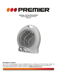
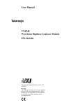
3 1 OSD - FUNCTION SETUP > PRESET SETUP 1 FUNCTION SETUP <FUNCTION SETUP> ==================================================== <PRESET SETUP> <SCAN SETUP> <PATTERN SETUP> <GROUP SETUP> Configure 4 special functions with this menu. 2 PRESET SETUP 255 presets from the number 1 to 255 can be assigned excluding preset 95, 131~134, 141~148, 151~158 reserved for menu. 1 ~ 255 PRESET NUMBER Selects the preset number to edit. BACK EXIT <EDIT SCENE> Define the current preset scene position(i.e. PTZ). Select ‘<PRESET SETUP>’ and press the ‘NEAR’ key 2 <PRESET SETUP> ==================================================== PRESET NUMBER <EDIT SCENE> CLEAR PRESET ALARM OUT 1 CANCEL ---- CANCEL / OK CLEAR PRESET Deletes current preset data. - - - - / 1234 ALARM OUT State of four alarm outputs can be freely controlled in conjunction with preset run. The character ‘ - ’ means off state and the number representing each bit means on. Ex) If it is set to be ‘ - 2 3 - ‘, output relay 2, 3 will be on and 1, 4 will be be off, when you run this preset. 3 EDIT SCENE 1) By PTZ controling, move camera to desired position. 2) By pressing the ‘NEAR’ key, the save current PTZ data. 3) If you want cancel the editing, press the ‘FAR’ key. BACK EXIT After define the ‘PRESET NUMBER’, select ‘<EDIT SCENE>’ and press the ‘NEAR’ key 3 <EDIT SCENE> ==================================================== MOVE TO TARGET POSITION [NEAR:SELECT/FAR:CANCEL] 20 3 1 OSD - FUNCTION SETUP > SCAN SETUP 2 SCAN SETUP <FUNCTION SETUP> ==================================================== <PRESET SETUP> <SCAN SETUP> <PATTERN SETUP> <GROUP SETUP> When scan function runs, the camera moves from the preset assigned as the 1st pos. to the preset assigned as the 2nd pos. in CW(Clockwise) direction. Then camera moves from the preset assigned as the 2nd pos. to the preset assigned as the 1st pos. in CCW(Counterclockwise) direction. Then, it continues to move from the 1st pos. to the 2nd pos. back and forth. BACK EXIT Select ‘<SCAN SETUP>’ and press the ‘NEAR’ key 2 <SCAN SETUP> ==================================================== SCAN NUMBER FIRST POSITION SECOND POSITION SCAN SPEED CLEAR SCAN Up to 8 scans are available, which makes the camera to move slowly between two preset positions. 1 NOT USED NOT USED 30/SEC CANCEL If the 1st POS. = the 2nd POS. In case that the preset assigned as the 1st pos. is same as the preset assigned as the 2nd pos., camera turns on its axis by 360° in CW direction and then it turns on its axis by 360° in CCW direction. If one preset is not defined between the 1st POS. and the 2nd POS. If case that a position assigned is ‘NOT USED’, camera turns on its axis by 360° in CW direction from the preset which is ‘NOT USED’ and then it turns on its axis by 360° in CCW direction. 1st POS. 2nd POS. BACK EXIT 2. CCW direction 1. CW direction 1~8 SCAN NUMBER Selects the scan number to edit. PRESET 1 ~ 255 / NOT USED FIRST POSITION Set up the 1st position for scan function. Undefined preset cannot be assigned as position. If you press ‘NEAR’ key when the selected undefined preset, the preset will returned to previous position(Available preset or ‘NOT USED’). PRESET 1 ~ 255 / NOT USED SECOND POSITION Same as the 1st position setup. SCAN SPEED Sets the scan speed. 1/SEC ~ 180/SEC CANCEL / OK CLEAR SCAN Deletes the current scan data. 21 3 1 OSD - FUNCTION SETUP > PATTERN SETUP 2 PATTERN SETUP <FUNCTION SETUP> ==================================================== <PRESET SETUP> <SCAN SETUP> <PATTERN SETUP> <GROUP SETUP> 4 patterns are available and max. 1000 communication commands can be stored in a pattern. PATTERN NUMBER 1~4 Select pattern number to edit. BACK EXIT <EDIT PATTERN> Starts editing pattern. Select ‘<PATTERN SETUP>’ and press the ‘NEAR’ key 2 Pattern function is that a camera memorizes the path (mostly curve path) by joystick of controller for assigned time and revives the path exactly as it memorized. 3 EDIT PATTERN - Select the Position <PATTERN SETUP> ==================================================== PATTERN NUMBER <EDIT PATTERN> CLEAR PATTERN CLEAR PATTERN CANCEL / OK Deletes data in the current pattern. 1 CANCEL 1) By using joystick, move to the start position with appropriate zoom. 2) To start the pattern recording, press the ‘NEAR’ or ‘ENTER’ key. 3) To exit this menu, press the ‘FAR’ key. 4 EDIT PATTERN - Records BACK EXIT After define the ‘PATTERN NUMBER’, select ‘<EDIT PATTERN>’ and press the ‘NEAR’ key 3 1) Move the camera with joystick of the controller or run preset function to memorize the path (mostly curve path) in a selected pattern. 2) The total memory size and the rest memory size is displayed in the form of bar. 3) To save data and exit, press the ‘NEAR’ key. 4) To cancel recording and delete the recorded data, press the ‘FAR’ key. <EDIT PATTERN> ==================================================== MOVE TO START POSITION [NEAR:START/FAR:CANCEL] After define starting position, press the ‘NEAR’ key to start recording 4 <EDIT PATTERN> ==================================================== [MEMORY] [NEAR:SAVE/FAR:DELETE] Memory size is displayed. To save data, press the ‘NEAR’ key. 22 3 1 OSD - FUNCTION SETUP > GROUP SETUP 2 GROUP SETUP SCREEN <FUNCTION SETUP> ==================================================== <PRESET SETUP> <SCAN SETUP> <PATTERN SETUP> <GROUP SETUP> The group function allows running sequence of presets, pattern and/or scans. Max. 8 group can be stored. Each group can have max. 20 action entities which can be preset, pattern or scan. Preset speed can be set up and the repeat number of pattern & scan can be set up in group setup. Dwell time between actions can be set up also. Dwell Time BACK EXIT Preset 1 Pattern5 1 Times Select ‘<GROUP SETUP>’ and press the ‘NEAR’ key 2 <GROUP SETUP> ==================================================== GROUP NUMBER <EDIT GROUP > CLEAR GROUP 1 CANCEL Pattern5 n Times Scan3 1 Preset 120 Max. 20 Entities 1~8 GROUP NUMBER Selects group number to edit. <EDIT GROUP> Starts editing group. CANCEL / OK CLEAR GROUP Deletes data in the current group. BACK EXIT 3 EDIT GROUP - Initial Screen Press the ‘NEAR’ key to start group setup. After define the ‘GROUP NUMBER’, select ‘<EDIT GROUP>’ and press the ‘NEAR’ key 3 ACTION NUM <EDIT GROUP> ==================================================== Num Dwell NO. ACTION OPT ==================================================== 1 NONE 2 NONE 3 NONE 4 NONE 5 NONE ==================================================== NONE / PRESET 1~255 / PATTERN 1~4 / SCAN 1~8 Select the function. 00:03 ~ 04:00 (min:sec) DWELL Sets dwell time between function by moving joystick up/down. If the ‘OPT’ of pattern/group is set to repeat more than twice, it means the repeat interval. PRESET: 1~360 / PATTERN & SCAN: 1~255 OPT It represents preset speed (1~360) when preset is selected. It should be the number of repetition (1~255) when pattern or scan is selected for ‘ACTION’. EDIT SAVE CANCEL Press the ‘NEAR’ key to start editing 4 1 ~ 20 NO. Means the sequence of the function in a group. The functions will be run from lower no. to higher no. by sequence. <EDIT GROUP> ==================================================== Num Dwell NO. ACTION OPT OPT ==================================================== 1 NONE 2 NONE 3 NONE 4 NONE 5 NONE ==================================================== 4 EDIT GROUP – Select Function Sequence Note that max. 20 functions are allowed in a group. Move cursor up/down and press the ‘NEAR’ key to set up. 5 EDIT GROUP - Assign Function Move cursor to the ‘NO.’ to assign the function, click the enter button to set up. Select the function by clicking up/down button. EDIT SAVE CANCEL Select function sequence number by move joystick up/down. And press the ‘NEAR’ key. 23 3 5 OSD - FUNCTION SETUP > GROUP SETUP <EDIT GROUP> ==================================================== NO. ACTION Num Dwell OPT ==================================================== 1 NONE 2 NONE 3 NONE 4 NONE 5 NONE ==================================================== EDIT SAVE CANCEL 5 EDIT GROUP - Assign Function Move cursor to the ‘NO.’ to assign the function, press the ‘NEAR’ key to set up. Select the function by moving joystick up/down. 6 EDIT GROUP - Assign Function Move cursor left/right to select items and move cursor up/down to change each value. 7 EDIT GROUP - Select Function Sequence e.g.) If ‘PRESET 1’ is not defined at ‘ROOT MENU>FUNCTION SETUP>PRESET SETUP’, then the ‘ACTION’ will be automatically changed to ‘NONE’. Move joystick up/down to select action. and move joystick right. 6 <EDIT GROUP> ==================================================== Num Dwell NO. OPT ACTION ==================================================== 1 00:02 1 PRESET 1 2 NONE 3 NONE <EDIT GROUP> ==================================================== Num Dwell NO. OPT ACTION ==================================================== 1 00:02 1 PRESET 1 2 NONE 3 NONE 4 NONE 5 NONE ==================================================== Press the ‘NEAR’ key <EDIT GROUP> ==================================================== Num Dwell NO. ACTION OPT ==================================================== 1 NONE 2 NONE 3 NONE EDIT SAVE CANCEL The function undefined cannot be set as action. 8 EDIT GROUP - Saves the Setting After define items, press the ‘NEAR’ key 7 After finishing setting up all actions, place cursor on ‘SAVE’. Then, press the ‘NEAR’ key to save current data. <EDIT GROUP> ==================================================== Num Dwell NO. ACTION OPT ==================================================== 1 00:02 1 PRESET 1 2 NONE 3 NONE 4 NONE 5 NONE ==================================================== EDIT SAVE CANCEL Press the ‘FAR’ key, and move joystick down to select ‘SAVE’ 8 <EDIT GROUP> ==================================================== Num Dwell NO. ACTION OPT ==================================================== 1 00:02 1 PRESET 1 2 NONE 3 NONE 4 NONE 5 NONE ==================================================== EDIT SAVE CANCEL Press the ‘NEAR’ key to save current data. 24 3 1 OSD - CAMERA SETUP 1 CAMERA SETUP <CAMERA SETUP> ==================================================== FOCUS MODE DIGITAL ZOOM <WHITE BALANCE SETUP> <AUTO EXPOSURE SETUP> <OTHER SETUP> AUTO OFF BACK EXIT <WHITE BALANCE SETUP> ==================================================== WB MODE R-GAIN B-GAIN AUTO / MANUAL FOCUS MODE Sets the camera focus mode. - AUTO: This mode exchanges the focus mode automatically between manual focus mode and auto focus mode. Manual focus mode activates in preset operation and auto focus mode activates when jog operation starts. - MANUAL: With manual mode at presets, focus data is memorized in each preset in advance and camera calls focus data in correspondence with presets as soon as camera arrives at a preset. ‘<ALARM INPUT SETUP>’ select and press the ‘NEAR’ Key 2 Setup the general functions of zoom camera module. AUTO 100 100 ON / OFF DIGITAL ZOOM Sets digital zoom function to ‘ON’ or ‘OFF’. If this is set to ‘OFF’, optical zoom function runs but zoom function stops at the end of optical zoom magnification. <WHITE BALANCE SETUP> Starts ‘WHITE BALANCE SETUP’ setup screen. <AUTO EXPOSURE SETUP> Starts ‘AUTO EXPOSURE SETUP’ setup screen. <OTHER SETUP> Starts ‘OTHER SETUP’ setup screen. BACK EXIT 2 WHITE BALANCE SETUP WB MODE AUTO / MANUAL / ONE PUSH> / OUTDOOR / INDOOR - AUTO: Camera perform white balance automatically. - Manual: ‘R/B-Gain’ level can be set up manually. - ONE PUSH: WB is executed once on the scene you designated. - INDOOR: WB will be done under assumption of Indoor illumination. - OUTDOOR: WB will be done under assumption of Sun light. RED ADJUST 0 ~ 255 BLUE ADJUST 0 ~ 255 25 3 1 OSD - CAMERA SETUP > AUTO EXPOSURE SETUP 2 AE SETUP <CAMERA SETUP> ==================================================== FOCUS MODE DIGITAL ZOOM <WHITE BALANCE SETUP> <AUTO EXPOSURE SETUP> <OTHER SETUP> AUTO OFF ON / OFF BACK LIGHT Sets the backlight compensation. AUTO / DAY / NIGHT DAY/NIGHT ‘AUTO’ exchanges day/night. AE MODE - AUTO: Full auto mode for AE function BACK EXIT - MANUAL: In manual mode. ‘IRIS’, ‘GAIN’, ‘SHUTTER SPEED’ can be changed in this mode. ‘<AUTO EXPOSURE SETUP>’ select and press the ‘NEAR’ Key 2 ==================================================== BACK LIGHT DAY/NIGHT AE MODE * SHUTTER * IRIS * GAIN * BRIGHT SLOW SHUTTER - IRIS: Iris priority mode. You can change iris while others are adjusted automatically. - SHUTTER: Shutter priority mode. Shutter speed can be changed while while others are adjusted automatically. - BRIGHT: In this mode, you can assign AE value in terms of brightness. <AUTO EXPOSURE SETUP> BACK EXIT AUTO / MANUAL / IRIS / SHUTTER / BRIGHT OFF AUTO AUTO 1/60 F2.0 4dB 20 ON IRIS LEVEL CLOSE / F1.8 / F2.0 / F2.4 / F2.8 / F3.4 / F4.0 / F4.8 / F5.6 / F6.8 / F8.0 / F9.6 / F11 / F14 / F16 / F19 / F22 / F26 (18 steps) Works when ‘AE MODE’ is ‘MANUAL’ or ‘IRIS’ mode. GAIN LEVEL -3 / 0 / 3 / 6 / 9 / 12 / 15 Works when ‘AE MODE’ is ‘MANUAL’. Enhances image brightness automatically in case that luminance level of image signal is too low. 1/2 ~ 1/10000 (21 steps) SHUTTER SPD Works when ‘AE MODE’ is ‘MANUAL’ or ‘SHUTTER’ mode. 0~31 (32 steps) BRIGHTNESS Works when ‘AE MODE’ is ‘BRIGHT’. Adjusts brightness of images. Iris, shutter speed and gain are adjusted automatically in correspondence with this value. ON / OFF SLOW SHUTTER Turn On/Off slow shutter function. If you turn this on, the shutter speed is slowed down to intensify image by accumulating small light in the extremely dark environment. This function is effective only in Full Auto AE mode. 26 3 1 OSD - CAMERA SETUP > OTHER SETUP 2 OTHER SETUP <CAMERA SETUP> ==================================================== FOCUS MODE DIGITAL ZOOM <WHITE BALANCE SETUP> <AUTO EXPOSURE SETUP> <OTHER SETUP> AUTO OFF ‘<OTHER SETUP>’ select and press the ‘NEAR’ Key <OTHER SETUP> ==================================================== EXP COMPENSATION APERTURE GAMMA PICTURE EFFECT WIDE-D IR CORRECTION CAM GAIN HR MODE NOISE REDUCTION HIGH SENSITIVITY BACK EXIT 7 (GAIN:-10.5dB) ~ +7 (GAIN:+10.5dB) (15 Steps) Default is ‘0/0dB’. BACK EXIT 2 EXP COMPENSATION 0 6 NORMAL OFF OFF OFF 20dB ON 3 ON APERTURE 0 ~ 15 GAMMA NORMAL / GAMMA1 / S-LOW / S-MID / S-HIGH PICTURE EFFECT OFF / NEGATIVE / B&W WIDE-D ON / OFF IR CORRECTION ON / OFF CAM GAIN 6 dB ~ 20 dB HR MODE ON / OFF NOISE REDUCTION OFF / 1 ~ 5 HIGH SENSITIVITY ON / OFF 27 3 1 OSD - SYSTEM SETUP 2 SYSTEM SETUP <SYSTEM SETUP> ==================================================== HD-SDI CLEAR ALL DATA 1920x1080i60 CANCEL HD-SDI 1280x720p50 / 1280x720p60 / 1920x1080i50 / 1920x1080i60 / 1920x1080p25 / 1920x1080p30 Select the resolution of HD-SDI. CANCEL / OK CLEAR ALL DATA Deletes all configuration data such as display, camera, motion setup and so on. BACK EXIT 28 4 Specifications - Dimension Unit: mm 102 286 142 182.5 187 71 3/4” PIP THREAD 78.7 146 259 404.5 Wall Mount Bracket 132 182.5 71 3/4” PIP THREAD 383 142 102 187 3/4” PIP THREAD 78.7 146 259 Ceiling Mount Bracket 29